RU2434142C2 - Journal bearing for rotary blade of stator with changeable angle of setting, blade of guiding mechanism of impeller machine containing above said bearing (versions), impeller machine (versions) - Google Patents
Journal bearing for rotary blade of stator with changeable angle of setting, blade of guiding mechanism of impeller machine containing above said bearing (versions), impeller machine (versions) Download PDFInfo
- Publication number
- RU2434142C2 RU2434142C2 RU2007123186/06A RU2007123186A RU2434142C2 RU 2434142 C2 RU2434142 C2 RU 2434142C2 RU 2007123186/06 A RU2007123186/06 A RU 2007123186/06A RU 2007123186 A RU2007123186 A RU 2007123186A RU 2434142 C2 RU2434142 C2 RU 2434142C2
- Authority
- RU
- Russia
- Prior art keywords
- blade
- pin
- axis
- bearing
- versions
- Prior art date
Links
Images
Classifications
-
- F—MECHANICAL ENGINEERING; LIGHTING; HEATING; WEAPONS; BLASTING
- F04—POSITIVE - DISPLACEMENT MACHINES FOR LIQUIDS; PUMPS FOR LIQUIDS OR ELASTIC FLUIDS
- F04D—NON-POSITIVE-DISPLACEMENT PUMPS
- F04D29/00—Details, component parts, or accessories
- F04D29/40—Casings; Connections of working fluid
- F04D29/52—Casings; Connections of working fluid for axial pumps
- F04D29/54—Fluid-guiding means, e.g. diffusers
- F04D29/56—Fluid-guiding means, e.g. diffusers adjustable
- F04D29/563—Fluid-guiding means, e.g. diffusers adjustable specially adapted for elastic fluid pumps
-
- F—MECHANICAL ENGINEERING; LIGHTING; HEATING; WEAPONS; BLASTING
- F01—MACHINES OR ENGINES IN GENERAL; ENGINE PLANTS IN GENERAL; STEAM ENGINES
- F01D—NON-POSITIVE DISPLACEMENT MACHINES OR ENGINES, e.g. STEAM TURBINES
- F01D17/00—Regulating or controlling by varying flow
- F01D17/10—Final actuators
- F01D17/12—Final actuators arranged in stator parts
- F01D17/14—Final actuators arranged in stator parts varying effective cross-sectional area of nozzles or guide conduits
- F01D17/16—Final actuators arranged in stator parts varying effective cross-sectional area of nozzles or guide conduits by means of nozzle vanes
- F01D17/162—Final actuators arranged in stator parts varying effective cross-sectional area of nozzles or guide conduits by means of nozzle vanes for axial flow, i.e. the vanes turning around axes which are essentially perpendicular to the rotor centre line
-
- F—MECHANICAL ENGINEERING; LIGHTING; HEATING; WEAPONS; BLASTING
- F04—POSITIVE - DISPLACEMENT MACHINES FOR LIQUIDS; PUMPS FOR LIQUIDS OR ELASTIC FLUIDS
- F04D—NON-POSITIVE-DISPLACEMENT PUMPS
- F04D29/00—Details, component parts, or accessories
- F04D29/05—Shafts or bearings, or assemblies thereof, specially adapted for elastic fluid pumps
- F04D29/056—Bearings
- F04D29/057—Bearings hydrostatic; hydrodynamic
-
- F—MECHANICAL ENGINEERING; LIGHTING; HEATING; WEAPONS; BLASTING
- F16—ENGINEERING ELEMENTS AND UNITS; GENERAL MEASURES FOR PRODUCING AND MAINTAINING EFFECTIVE FUNCTIONING OF MACHINES OR INSTALLATIONS; THERMAL INSULATION IN GENERAL
- F16F—SPRINGS; SHOCK-ABSORBERS; MEANS FOR DAMPING VIBRATION
- F16F1/00—Springs
- F16F1/36—Springs made of rubber or other material having high internal friction, e.g. thermoplastic elastomers
- F16F1/38—Springs made of rubber or other material having high internal friction, e.g. thermoplastic elastomers with a sleeve of elastic material between a rigid outer sleeve and a rigid inner sleeve or pin, i.e. bushing-type
- F16F1/3863—Springs made of rubber or other material having high internal friction, e.g. thermoplastic elastomers with a sleeve of elastic material between a rigid outer sleeve and a rigid inner sleeve or pin, i.e. bushing-type characterised by the rigid sleeves or pin, e.g. of non-circular cross-section
-
- F—MECHANICAL ENGINEERING; LIGHTING; HEATING; WEAPONS; BLASTING
- F05—INDEXING SCHEMES RELATING TO ENGINES OR PUMPS IN VARIOUS SUBCLASSES OF CLASSES F01-F04
- F05D—INDEXING SCHEME FOR ASPECTS RELATING TO NON-POSITIVE-DISPLACEMENT MACHINES OR ENGINES, GAS-TURBINES OR JET-PROPULSION PLANTS
- F05D2300/00—Materials; Properties thereof
- F05D2300/40—Organic materials
- F05D2300/43—Synthetic polymers, e.g. plastics; Rubber
- F05D2300/431—Rubber
-
- F—MECHANICAL ENGINEERING; LIGHTING; HEATING; WEAPONS; BLASTING
- F05—INDEXING SCHEMES RELATING TO ENGINES OR PUMPS IN VARIOUS SUBCLASSES OF CLASSES F01-F04
- F05D—INDEXING SCHEME FOR ASPECTS RELATING TO NON-POSITIVE-DISPLACEMENT MACHINES OR ENGINES, GAS-TURBINES OR JET-PROPULSION PLANTS
- F05D2300/00—Materials; Properties thereof
- F05D2300/50—Intrinsic material properties or characteristics
- F05D2300/501—Elasticity
Landscapes
- Engineering & Computer Science (AREA)
- General Engineering & Computer Science (AREA)
- Mechanical Engineering (AREA)
- Physics & Mathematics (AREA)
- Fluid Mechanics (AREA)
- Structures Of Non-Positive Displacement Pumps (AREA)
- Support Of The Bearing (AREA)
- Control Of Turbines (AREA)
- Turbine Rotor Nozzle Sealing (AREA)
Abstract
Description
Настоящее изобретение относится к области лопаточных машин, таких как осевой компрессор газотурбинного двигателя, и, в частности, касается поворотных лопаток статора с изменяемым углом установки.The present invention relates to the field of blade machines, such as an axial compressor of a gas turbine engine, and, in particular, relates to rotary stator vanes with a variable installation angle.
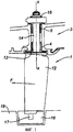
Шарнирная система, в частности в виде поворотных лопаток направляющего аппарата с изменяемым углом установки компрессора газотурбинного двигателя, содержит детали, подвижные относительно друг друга. На фиг.1 схематично показана поворотная лопатка 1 направляющего аппарата с изменяемым углом установки, установленная в картере 3 машины. Лопатка статора содержит перо 12, площадку или платформу 13 и стержень, образующий на одном конце поворотный шкворень 14. Шкворень 14 установлен в радиальном отверстии, выполненном в стенке картера 3, в нескольких опорных подшипниках. Лопатка крепится только этим концом. На другом конце находится плавающий кольцевой элемент 16, в котором он установлен с возможностью поворота при помощи второго поворотного шкворня 17. Кольцо оборудовано средствами уплотнения смежной с ним части ротора 18.The hinge system, in particular in the form of rotary blades of a guide vane with a variable installation angle of the compressor of a gas turbine engine, contains parts that are movable relative to each other. Figure 1 schematically shows the rotary blade 1 of the guide apparatus with a variable installation angle mounted in the
Шкворень 14 поворачивается в соответствующем отверстии картера в опорных подшипниках, например в нижнем опорном подшипнике 4 со стороны площадки. Площадка 13 установлена в полости в виде зенкованного углубления, выполненного в стенке картера. Стенка картера находится в радиальном контакте с площадкой 13 либо непосредственно, либо через втулку или шайбу. Верхняя часть шкворня 14 удерживается в верхнем опорном подшипнике 5. Опорные подшипники 4 и 5 выполнены, например, в виде втулок, установленных в отверстии картера и содержащих внутреннее кольцо, образующее поверхность трения со стержнем 14, образующим поворотный шкворень.The
Сторона площадки 13, противоположная опорному подшипнику 4, образует основание лопатки и обдувается газами, приводимыми в движение компрессором. Эта сторона площадки выполнена с возможностью обеспечения непрерывности контура, образованного картером. Гайка 15' удерживает лопатку в ее гнезде, и рычаг, приводимый в действие соответствующими органами управления, управляет вращением лопатки вокруг оси XX стержня, устанавливая ее в необходимое положение относительно направления газового потока. Относительные движения происходят за счет взаимного скольжения находящихся в контакте поверхностей.The side of the
В случае осевого компрессора газотурбинного двигателя или просто осевого компрессора для воздуха или другого газа, такого как доменный газ или природный газ, перо 12 лопатки по всей своей длине подвергается воздействию аэродинамических усилий и давлению со стороны газового потока. Составляющая этих усилий, перпендикулярная к хорде в направлении спинки лопатки и проходящая, как правило, через ось поворотного шкворня, имеет самое большое значение. Отмечается также, что в случае значительных поворотов составляющая может отходить от этой оси. Перо подвергается также воздействию осевых усилий статического давления, направленных в сторону входа, за счет разности давления между выходом и входом. Результирующая сила на фигуре показана стрелкой F. В результате происходит приложение момента, который соединяется с установочным поворотом вокруг оси XX по амплитуде, которая может достигать и превышать 40 градусов.In the case of an axial compressor of a gas turbine engine or simply an axial compressor for air or other gas, such as blast furnace gas or natural gas, the
Как было указано выше, втулки, устанавливаемые под рычагами поворотной системы, не допускают никакого другого движения, кроме поворота вокруг оси шкворня. Вместе с тем отмечается, что, с учетом поперечных усилий и усилий изгиба направляющих лопаток, втулки из известных технических решений подвергаются неравномерному износу. Такой износ мешает нормальной работе поворотного устройства.As mentioned above, the bushings mounted under the levers of the rotary system do not allow any other movement than rotation around the axis of the kingpin. However, it is noted that, taking into account the transverse forces and the bending forces of the guide vanes, the bushings of the known technical solutions undergo uneven wear. Such wear interferes with the normal operation of the rotary device.
Заявитель поставил перед собой задачу создания средств для установки поворотных лопаток с изменяемым углом установки вышеупомянутого типа, которые не подвергаются или меньше подвергаются износу.The applicant has set himself the task of creating means for installing rotary blades with a variable installation angle of the aforementioned type, which are not subject to wear or less.
Эта задача решается благодаря настоящему изобретению, объектом которого является опорный подшипник для поворотного шкворня поворотной лопатки направляющего аппарата с изменяемым углом установки лопаточной машины, установленный в отверстии картера лопаточной машины, отличающийся тем, что содержит внутреннюю втулку, неподвижно соединенную с упомянутой осью, и наружную втулку, неподвижно соединенную с упомянутым отверстием, при этом между внутренней втулкой и наружной втулкой помещают эластомерный материал, обеспечивающий поворот лопатки вокруг своей оси и, по меньшей мере, частичное поглощение усилия изгиба поворотного шкворня, перпендикулярного к оси.This problem is solved thanks to the present invention, the object of which is a support bearing for a pivot shaft of a rotary vane of a guide vane with a variable blade angle installed in the hole of the vane carter, characterized in that it contains an inner sleeve fixedly connected to the said axis and an outer sleeve fixedly connected to said hole, while between the inner sleeve and the outer sleeve an elastomeric material is placed to rotate atki around its axis and, at least partial absorption of the bending force of the pivot, perpendicular to the axis.
Благодаря этому отличительному признаку, опорный подшипник работает наподобие шаровой опоры и позволяет увеличить действительную поверхность между поворотным шкворнем и наружной втулкой.Due to this distinguishing feature, the thrust bearing works like a ball bearing and allows you to increase the actual surface between the pivot pin and the outer sleeve.
Преимуществом конструкции втулки в соответствии с настоящим изобретением является также то, что, в случае необходимости, она может производить амортизирующий эффект. Он позволяет рассеивать энергию вибрации, когда направляющий аппарат подвергается аэродинамическим воздействиям.An advantage of the design of the sleeve in accordance with the present invention is that, if necessary, it can produce a shock-absorbing effect. It allows you to dissipate vibration energy when the guide vane is subjected to aerodynamic influences.
Предпочтительно, чтобы внутренняя втулка подразделялась, по меньшей мере, на два цилиндрических элемента, продолжающих друг друга. Это позволяет внутренней втулке адаптироваться к деформациям поворотного шкворня. Число составных элементов внутренней втулки можно увеличить, чтобы обеспечить максимально надежную адаптацию.Preferably, the inner sleeve is subdivided into at least two cylindrical elements extending each other. This allows the inner sleeve to adapt to the deformations of the pivot pin. The number of components of the inner sleeve can be increased to ensure the most reliable adaptation.
В частности, различные элементы отделены друг от друга кольцевым слоем эластомера, улучшающим герметичность вдоль поворотного шкворня.In particular, the various elements are separated from each other by an annular layer of elastomer, which improves tightness along the pivot shaft.
Такая конструкция опорного подшипника является предпочтительной, когда ее применяют для опорного подшипника, установленного под приводным рычагом направляющего аппарата.This design of the support bearing is preferred when it is used for a support bearing mounted under the drive arm of the guide apparatus.
Далее следует подробное описание изобретения со ссылками на прилагаемые чертежи.The following is a detailed description of the invention with reference to the accompanying drawings.
Фиг.1 представляет вид сбоку в разрезе поворотной лопатки направляющего аппарата, установленной в отверстии картера лопаточной машины, из предшествующего уровня техники.Figure 1 is a side view in section of a rotary blade of the guide apparatus installed in the hole of the crankcase of the blade of the prior art.
Фиг.2 - увеличенный вид сбоку в разрезе части поворотного шкворня со стороны тяги управления с монтажом в соответствии с настоящим изобретением.Figure 2 is an enlarged side view in section of part of the pivot pin from the control rod with mounting in accordance with the present invention.
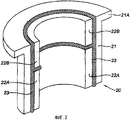
Фиг.3 - вид в разрезе и в изометрии отдельно взятого опорного подшипника в соответствии с настоящим изобретением.Figure 3 is a view in section and in isometric view of a single pillow block bearing in accordance with the present invention.
На фиг.2 показан поворотный шкворень 14 лопатки 1, установленный в отверстии картера 3 с возможностью обеспечения поворота вокруг оси XX. Поворотный шкворень заканчивается цапфой 15, на которой при помощи гайки 15' закреплена приводная тяга 19, поворачивающая лопатку в угловом направлении вокруг оси XX.Figure 2 shows the
Поворотный шкворень установлен в опорном подшипнике 4 со стороны площадки 13 - перо лопатки не показано - и в опорном подшипнике 20 со стороны тяги 19. Объектом изобретения является опорный подшипник 20. Он содержит наружную втулку 21, посаженную внатяг в отверстие картера 3. Таким образом, эта наружная втулка является цилиндрической и содержит поперечный фланец 21А, опирающийся на наружный край отверстия. Этот фланец установлен между картером и тягой 19.The pivot pin is installed in the thrust bearing 4 from the side of the
Внутренняя втулка 22, состоящая из двух цилиндрических элементов 22А и 22В, слегка отстоящих друг от друга в осевом направлении, посажена внатяг на поворотный шкворень 14. Эта внутренняя втулка расположена в осевом направлении по той же длине, что и наружная втулка 21.The inner sleeve 22, consisting of two
Между двумя втулками оставлено пространство, заполненное эластомерным материалом. Предпочтительно этот материал сцепляется с двумя втулками 21 и 22 и заполняет пространство между двумя цилиндрическими элементами 22А и 22В. На фиг.3 более детально показано взаимное расположение втулок.Between the two bushings left space filled with elastomeric material. Preferably, this material adheres to two
Эластомерный материал выбирают таким образом, чтобы при деформации он позволял одной втулке поворачиваться относительно другой втулки в соответствии с регулировочной установкой поворота для данного направляющего аппарата.The elastomeric material is selected so that during deformation it allows one sleeve to rotate relative to another sleeve in accordance with the adjusting rotation setting for this guide apparatus.
Толщина эластомерного материала также является одним из параметров, который необходимо учитывать при выполнении опорного подшипника.The thickness of the elastomeric material is also one of the parameters that must be taken into account when making a thrust bearing.
Заполняя кольцевое пространство между двумя элементами 22А и 22 В втулки, эластомер участвует в уплотнении вдоль поверхности поворотного шкворня. Следует заметить, что на фигуре показаны только два элемента, однако внутренняя втулка может содержать несколько элементов.Filling the annular space between the two
Во время работы эластомерный материал сопровождает движения поворота шкворня вокруг оси XX, обеспечивая при этом хорошее уплотнение, а также поглощает усилия, действующие на шкворень в поперечном направлении, и распределяет их по поверхности, большей, чем в случае гладкого и жесткого контакта между подвижными деталями.During operation, the elastomeric material accompanies the movement of the kingpin rotation around the XX axis, while ensuring good sealing, and also absorbs the forces acting on the kingpin in the transverse direction, and distributes them over a surface greater than in the case of smooth and hard contact between moving parts.
Подшипник в соответствии с настоящим изобретением представлен в применении к наружной опоре поворотного шкворня, однако его можно применять в других зонах, где это позволяет окружающая среда, в частности термическая среда.The bearing in accordance with the present invention is presented as applied to the outer support of a pivot pin, however, it can be used in other areas where the environment, in particular the thermal environment, allows.
Claims (2)
Applications Claiming Priority (2)
| Application Number | Priority Date | Filing Date | Title |
|---|---|---|---|
| FR0652565A FR2902822B1 (en) | 2006-06-21 | 2006-06-21 | STATOR BEARING FOR STATOR WITH VARIABLE SHAFT |
| FR0652565 | 2006-06-21 |
Publications (2)
| Publication Number | Publication Date |
|---|---|
| RU2007123186A RU2007123186A (en) | 2008-12-27 |
| RU2434142C2 true RU2434142C2 (en) | 2011-11-20 |
Family
ID=37497055
Family Applications (1)
| Application Number | Title | Priority Date | Filing Date |
|---|---|---|---|
| RU2007123186/06A RU2434142C2 (en) | 2006-06-21 | 2007-06-20 | Journal bearing for rotary blade of stator with changeable angle of setting, blade of guiding mechanism of impeller machine containing above said bearing (versions), impeller machine (versions) |
Country Status (6)
| Country | Link |
|---|---|
| US (1) | US8038387B2 (en) |
| EP (1) | EP1870600B1 (en) |
| JP (1) | JP5142061B2 (en) |
| CA (1) | CA2592791C (en) |
| FR (1) | FR2902822B1 (en) |
| RU (1) | RU2434142C2 (en) |
Families Citing this family (25)
| Publication number | Priority date | Publication date | Assignee | Title |
|---|---|---|---|---|
| FR2920469A1 (en) | 2007-08-30 | 2009-03-06 | Snecma Sa | TURBOMACHINE VARIABLE CALIBRATION |
| US9410443B2 (en) * | 2012-01-27 | 2016-08-09 | United Technologies Corporation | Variable vane damping assembly |
| US9334751B2 (en) * | 2012-04-03 | 2016-05-10 | United Technologies Corporation | Variable vane inner platform damping |
| US9341194B2 (en) * | 2012-11-01 | 2016-05-17 | Solar Turbines Incorporated | Gas turbine engine compressor with a biased inner ring |
| US10215048B2 (en) | 2013-01-21 | 2019-02-26 | United Technologies Corporation | Variable area vane arrangement for a turbine engine |
| US10047629B2 (en) | 2013-01-28 | 2018-08-14 | United Technologies Corporation | Multi-segment adjustable stator vane for a variable area vane arrangement |
| WO2015050607A2 (en) | 2013-07-08 | 2015-04-09 | United Technologies Corporation | Variable vane actuation system |
| US9670877B2 (en) * | 2013-07-15 | 2017-06-06 | United Technologies Corporation | Link arm drag reducing device |
| CN103410856B (en) * | 2013-07-18 | 2015-09-09 | 北京航空航天大学 | A kind of all-round flexible bearing based on looper effect |
| WO2015031058A1 (en) * | 2013-08-28 | 2015-03-05 | United Technologies Corporation | Variable vane bushing |
| WO2015094509A1 (en) * | 2013-12-16 | 2015-06-25 | United Technologies Corporation | Shortened support for compressor variable vane |
| EP2960438B1 (en) | 2014-06-26 | 2020-09-02 | MTU Aero Engines GmbH | Variable guide vane device for a gas turbine and gas turbine equipped with such a device |
| EP3009607A1 (en) * | 2014-10-13 | 2016-04-20 | United Technologies Corporation | Fixed-variable vane with potting in gap |
| EP3051063B1 (en) * | 2015-01-28 | 2019-10-09 | MTU Aero Engines GmbH | Variable guide vane, corresponding turbomachine and manufacturing method |
| DE102016215807A1 (en) * | 2016-08-23 | 2018-03-01 | MTU Aero Engines AG | Inner ring for a vane ring of a turbomachine |
| US11041401B2 (en) * | 2017-02-06 | 2021-06-22 | Mitsubishi Heavy Industries Compressor Corporation | Inlet guide vane and compressor |
| DE102017109952A1 (en) * | 2017-05-09 | 2018-11-15 | Rolls-Royce Deutschland Ltd & Co Kg | Rotor device of a turbomachine |
| KR20190021640A (en) * | 2017-08-23 | 2019-03-06 | 한화에어로스페이스 주식회사 | Inlet guide vane assembly |
| DE102018210601A1 (en) * | 2018-06-28 | 2020-01-02 | MTU Aero Engines AG | SEGMENT RING FOR ASSEMBLY IN A FLOWING MACHINE |
| DE102018213604A1 (en) * | 2018-08-13 | 2020-02-13 | Rolls-Royce Deutschland Ltd & Co Kg | Guide vane assembly with sealing element |
| FR3105290B1 (en) * | 2019-12-18 | 2021-11-26 | Safran Aircraft Engines | Turbomachine assembly |
| KR102265202B1 (en) * | 2019-12-18 | 2021-06-15 | 주식회사 포스코 | Apparatus and method for monitoring dust attached to stator blast of furnace power generator turbine |
| CN111015117A (en) * | 2019-12-25 | 2020-04-17 | 重庆跃进机械厂有限公司 | Machining method for bearing bush groove of marine engine |
| FR3120387B1 (en) * | 2021-03-08 | 2023-12-15 | Safran Aircraft Engines | Vibration damping ring for variable-pitch rectifier vane pivot of a turbomachine, bearing and rectifier vane comprising such a ring |
| GB202211449D0 (en) * | 2022-08-05 | 2022-09-21 | Dtr Vms Gmbh | Bush |
Family Cites Families (18)
| Publication number | Priority date | Publication date | Assignee | Title |
|---|---|---|---|---|
| US2932440A (en) * | 1955-05-20 | 1960-04-12 | Gen Electric | Compressor blade adjustment means |
| US2999630A (en) * | 1957-08-08 | 1961-09-12 | Gen Electric | Compressor |
| US3298762A (en) * | 1962-12-18 | 1967-01-17 | Gen Tire & Rubber Co | Self-lubricating joint |
| GB1199946A (en) * | 1967-10-05 | 1970-07-22 | Clevite Corp | Rubber Bushing for Brake Head |
| US3788763A (en) * | 1972-11-01 | 1974-01-29 | Gen Motors Corp | Variable vanes |
| US4050844A (en) * | 1976-06-01 | 1977-09-27 | United Technologies Corporation | Connection between vane arm and unison ring in variable area stator ring |
| US4765758A (en) * | 1985-01-07 | 1988-08-23 | Barry Wright Corporation | Laminated bearing |
| DE4102188C2 (en) * | 1991-01-25 | 1994-09-22 | Mtu Muenchen Gmbh | Guide vane adjustment device of a turbine of a gas turbine engine |
| JPH0651542U (en) * | 1992-12-22 | 1994-07-15 | 珍治 三木 | Rocking bearing |
| FR2784711B1 (en) * | 1998-10-16 | 2001-01-05 | Techlam | VANE VARIABLE SETTING ANGLE CONTROL DEVICE |
| FR2793521B1 (en) * | 1999-05-10 | 2005-09-23 | Techlam | VARIABLE CALIBRATION CONTROL ROD |
| US6413043B1 (en) * | 2000-11-09 | 2002-07-02 | General Electric Company | Inlet guide vane and shroud support contact |
| FR2853382B1 (en) * | 2003-04-04 | 2006-04-28 | Hispano Suiza Sa | FLEXIBLE BONDING SYSTEM BETWEEN A SATELLITE HOLDER AND THE FIXED SUPPORT IN A SPEED REDUCER |
| US6964521B2 (en) * | 2003-07-18 | 2005-11-15 | Honeywell International Inc. | Compliant linear bearing |
| FR2868490B1 (en) * | 2004-04-05 | 2006-07-28 | Snecma Moteurs Sa | CERAMIC SOCKET FOR A VARIABLE TURBOMACHINE AUBING TIMING SYSTEM |
| FR2880394B1 (en) * | 2005-01-06 | 2008-07-04 | Snecma Moteurs Sa | MOBILE PIECE GUIDING DEVICE |
| US7445427B2 (en) * | 2005-12-05 | 2008-11-04 | General Electric Company | Variable stator vane assembly and bushing thereof |
| JP5085150B2 (en) * | 2007-02-13 | 2012-11-28 | 東海ゴム工業株式会社 | Fan boss and its manufacturing method |
-
2006
- 2006-06-21 FR FR0652565A patent/FR2902822B1/en active Active
-
2007
- 2007-06-19 CA CA2592791A patent/CA2592791C/en active Active
- 2007-06-20 JP JP2007162153A patent/JP5142061B2/en active Active
- 2007-06-20 US US11/765,693 patent/US8038387B2/en active Active
- 2007-06-20 RU RU2007123186/06A patent/RU2434142C2/en active
- 2007-06-20 EP EP07110629.8A patent/EP1870600B1/en active Active
Also Published As
| Publication number | Publication date |
|---|---|
| FR2902822A1 (en) | 2007-12-28 |
| US20080031730A1 (en) | 2008-02-07 |
| EP1870600A1 (en) | 2007-12-26 |
| EP1870600B1 (en) | 2016-09-14 |
| FR2902822B1 (en) | 2008-08-22 |
| CA2592791A1 (en) | 2007-12-21 |
| JP2008002469A (en) | 2008-01-10 |
| CA2592791C (en) | 2014-05-20 |
| US8038387B2 (en) | 2011-10-18 |
| JP5142061B2 (en) | 2013-02-13 |
| RU2007123186A (en) | 2008-12-27 |
Similar Documents
| Publication | Publication Date | Title |
|---|---|---|
| RU2434142C2 (en) | Journal bearing for rotary blade of stator with changeable angle of setting, blade of guiding mechanism of impeller machine containing above said bearing (versions), impeller machine (versions) | |
| JP5126505B2 (en) | Variable pitch blade control | |
| RU2436967C2 (en) | Stator blade of gas turbine engine with adjustable setting angle, and gas turbine engine | |
| US4741666A (en) | Variable displacement turbocharger | |
| CA2560815C (en) | Actuator for adjusting a rotor blade pitch angle | |
| NO325885B1 (en) | bushing | |
| KR100814169B1 (en) | Torque tube bearing assembly | |
| JPH048602B2 (en) | ||
| JP4355915B2 (en) | Method and apparatus for regulating fluid flow in a gas turbine engine | |
| CN105408206A (en) | Propeller blade mounting device | |
| RU2490476C2 (en) | Guide stage of compressor of gas-turbine engine with blades with variable setting angle, and gas-turbine engine | |
| JP4522929B2 (en) | Spring clamp clip | |
| RU2700113C2 (en) | Control system of blades with variable angle of installation for gas turbine engine | |
| FI67606B (en) | VENTILVRIDNINGSANORDNING | |
| JPH08145051A (en) | Water lubricated ceramic bearing device, pump and water wheel | |
| CN110546377A (en) | Joint for the vibratory connection of a rotor of a wind turbine to a crankshaft | |
| US2932440A (en) | Compressor blade adjustment means | |
| CN101978170A (en) | Device for changing a pitch of a blade of an impeller/propeller and a fan comprising the device | |
| CN116964301A (en) | Bearing for a variable pitch stator blade pivot of a turbomachine, stator blade comprising such a bearing and turbomachine comprising such a stator blade | |
| RU2338072C2 (en) | Attachment of drive lever allowing taking up clearance in variable-blade-angle turbine | |
| JP4073794B2 (en) | Variable angle vane control device with loose connection | |
| KR100643692B1 (en) | Air foil bearing | |
| JP2007002725A (en) | Winding bush for repair and support bearing device for gas turbine variable stator blade | |
| RU2257493C2 (en) | Compressor of gas-turbine engine | |
| RU2674173C1 (en) | Device to control guide vanes of compressor of gas turbine engine |
Legal Events
| Date | Code | Title | Description |
|---|---|---|---|
| PD4A | Correction of name of patent owner |