RU2431813C2 - Wave front transducer - Google Patents
Wave front transducer Download PDFInfo
- Publication number
- RU2431813C2 RU2431813C2 RU2008134018/28A RU2008134018A RU2431813C2 RU 2431813 C2 RU2431813 C2 RU 2431813C2 RU 2008134018/28 A RU2008134018/28 A RU 2008134018/28A RU 2008134018 A RU2008134018 A RU 2008134018A RU 2431813 C2 RU2431813 C2 RU 2431813C2
- Authority
- RU
- Russia
- Prior art keywords
- wavefront
- incident
- aperture
- shifted
- sensitive device
- Prior art date
Links
- 230000003287 optical effect Effects 0.000 claims abstract description 48
- 230000004075 alteration Effects 0.000 claims abstract description 37
- 201000009310 astigmatism Diseases 0.000 claims abstract description 37
- 238000000034 method Methods 0.000 claims abstract description 24
- 238000012937 correction Methods 0.000 claims description 15
- 230000008859 change Effects 0.000 claims description 11
- 238000006073 displacement reaction Methods 0.000 claims description 8
- 230000002159 abnormal effect Effects 0.000 claims description 7
- 230000005540 biological transmission Effects 0.000 claims description 4
- 238000001514 detection method Methods 0.000 claims description 3
- 230000035945 sensitivity Effects 0.000 claims description 3
- 230000010349 pulsation Effects 0.000 claims 1
- 230000001105 regulatory effect Effects 0.000 claims 1
- 230000003362 replicative effect Effects 0.000 claims 1
- 235000010627 Phaseolus vulgaris Nutrition 0.000 abstract 1
- 244000046052 Phaseolus vulgaris Species 0.000 abstract 1
- 230000000694 effects Effects 0.000 abstract 1
- 239000000126 substance Substances 0.000 abstract 1
- 230000010287 polarization Effects 0.000 description 10
- 238000005259 measurement Methods 0.000 description 6
- 238000012634 optical imaging Methods 0.000 description 6
- 210000004027 cell Anatomy 0.000 description 5
- 210000001525 retina Anatomy 0.000 description 5
- 239000004973 liquid crystal related substance Substances 0.000 description 4
- 210000001747 pupil Anatomy 0.000 description 4
- 230000008901 benefit Effects 0.000 description 3
- 210000004087 cornea Anatomy 0.000 description 3
- 238000003384 imaging method Methods 0.000 description 3
- 230000000903 blocking effect Effects 0.000 description 2
- 238000012512 characterization method Methods 0.000 description 2
- 238000004590 computer program Methods 0.000 description 2
- 238000010586 diagram Methods 0.000 description 2
- 239000007788 liquid Substances 0.000 description 2
- 230000004048 modification Effects 0.000 description 2
- 238000012986 modification Methods 0.000 description 2
- 238000002834 transmittance Methods 0.000 description 2
- 206010027646 Miosis Diseases 0.000 description 1
- 230000003044 adaptive effect Effects 0.000 description 1
- 238000003491 array Methods 0.000 description 1
- 230000001427 coherent effect Effects 0.000 description 1
- 210000002858 crystal cell Anatomy 0.000 description 1
- 230000003247 decreasing effect Effects 0.000 description 1
- 230000005672 electromagnetic field Effects 0.000 description 1
- 230000001788 irregular Effects 0.000 description 1
- 239000000463 material Substances 0.000 description 1
- 230000008569 process Effects 0.000 description 1
- 238000012545 processing Methods 0.000 description 1
- 238000011897 real-time detection Methods 0.000 description 1
- 239000012925 reference material Substances 0.000 description 1
- 239000007787 solid Substances 0.000 description 1
- 230000003068 static effect Effects 0.000 description 1
- 238000012546 transfer Methods 0.000 description 1
Images


Classifications
-
- G—PHYSICS
- G01—MEASURING; TESTING
- G01J—MEASUREMENT OF INTENSITY, VELOCITY, SPECTRAL CONTENT, POLARISATION, PHASE OR PULSE CHARACTERISTICS OF INFRARED, VISIBLE OR ULTRAVIOLET LIGHT; COLORIMETRY; RADIATION PYROMETRY
- G01J9/00—Measuring optical phase difference; Determining degree of coherence; Measuring optical wavelength
-
- A—HUMAN NECESSITIES
- A61—MEDICAL OR VETERINARY SCIENCE; HYGIENE
- A61B—DIAGNOSIS; SURGERY; IDENTIFICATION
- A61B3/00—Apparatus for testing the eyes; Instruments for examining the eyes
- A61B3/10—Objective types, i.e. instruments for examining the eyes independent of the patients' perceptions or reactions
- A61B3/1015—Objective types, i.e. instruments for examining the eyes independent of the patients' perceptions or reactions for wavefront analysis
-
- A—HUMAN NECESSITIES
- A61—MEDICAL OR VETERINARY SCIENCE; HYGIENE
- A61B—DIAGNOSIS; SURGERY; IDENTIFICATION
- A61B3/00—Apparatus for testing the eyes; Instruments for examining the eyes
- A61B3/10—Objective types, i.e. instruments for examining the eyes independent of the patients' perceptions or reactions
- A61B3/12—Objective types, i.e. instruments for examining the eyes independent of the patients' perceptions or reactions for looking at the eye fundus, e.g. ophthalmoscopes
-
- A—HUMAN NECESSITIES
- A61—MEDICAL OR VETERINARY SCIENCE; HYGIENE
- A61B—DIAGNOSIS; SURGERY; IDENTIFICATION
- A61B3/00—Apparatus for testing the eyes; Instruments for examining the eyes
- A61B3/10—Objective types, i.e. instruments for examining the eyes independent of the patients' perceptions or reactions
- A61B3/14—Arrangements specially adapted for eye photography
-
- G—PHYSICS
- G01—MEASURING; TESTING
- G01J—MEASUREMENT OF INTENSITY, VELOCITY, SPECTRAL CONTENT, POLARISATION, PHASE OR PULSE CHARACTERISTICS OF INFRARED, VISIBLE OR ULTRAVIOLET LIGHT; COLORIMETRY; RADIATION PYROMETRY
- G01J1/00—Photometry, e.g. photographic exposure meter
- G01J1/02—Details
- G01J1/04—Optical or mechanical part supplementary adjustable parts
- G01J1/0407—Optical elements not provided otherwise, e.g. manifolds, windows, holograms, gratings
- G01J1/0414—Optical elements not provided otherwise, e.g. manifolds, windows, holograms, gratings using plane or convex mirrors, parallel phase plates, or plane beam-splitters
-
- G—PHYSICS
- G01—MEASURING; TESTING
- G01J—MEASUREMENT OF INTENSITY, VELOCITY, SPECTRAL CONTENT, POLARISATION, PHASE OR PULSE CHARACTERISTICS OF INFRARED, VISIBLE OR ULTRAVIOLET LIGHT; COLORIMETRY; RADIATION PYROMETRY
- G01J1/00—Photometry, e.g. photographic exposure meter
- G01J1/02—Details
- G01J1/04—Optical or mechanical part supplementary adjustable parts
- G01J1/0407—Optical elements not provided otherwise, e.g. manifolds, windows, holograms, gratings
- G01J1/0437—Optical elements not provided otherwise, e.g. manifolds, windows, holograms, gratings using masks, aperture plates, spatial light modulators, spatial filters, e.g. reflective filters
-
- G—PHYSICS
- G01—MEASURING; TESTING
- G01J—MEASUREMENT OF INTENSITY, VELOCITY, SPECTRAL CONTENT, POLARISATION, PHASE OR PULSE CHARACTERISTICS OF INFRARED, VISIBLE OR ULTRAVIOLET LIGHT; COLORIMETRY; RADIATION PYROMETRY
- G01J3/00—Spectrometry; Spectrophotometry; Monochromators; Measuring colours
- G01J3/02—Details
- G01J3/06—Scanning arrangements arrangements for order-selection
Abstract
Description
Предпосылки изобретенияBACKGROUND OF THE INVENTION
Датчики волновых фронтов являются устройствами, применяемыми для оценки формы волнового фронта светового пучка (см., например, US 4141652). В большинстве случаев датчик волнового фронта измеряет отклонение волнового фронта от опорного волнового фронта или идеального волнового фронта, например плоского волнового фронта. Датчик волнового фронта можно использовать для измерения как аберраций низшего порядка, так и аберраций высшего порядка различных оптических систем формирования изображения, таких как человеческий глаз (см., например, J.Liang и др. (1994) "Объективные измерения волновых аберраций человеческого глаза с помощью датчика волновых фронтов Гартмана-Шака", J.Opt.Soc.Am. A-11, 1949-1957; T.Dave (2004) "Измерение аберрации волнового фронта, часть 1: Современные теории и концепции", Оптометрия сегодня, 2004, 19 ноября, с.41-45). Кроме того, датчик волновых фронтов можно также использовать в адаптивной оптической системе, в которой искаженный волновой фронт можно измерить и скомпенсировать в реальном времени, используя, например, оптическое устройство компенсации волнового фронта, такое как деформируемое зеркало. В результате такой компенсации можно получить четкое изображение (см., например, US 5777719).Wavefront sensors are devices used to evaluate the wavefront shape of a light beam (see, for example, US 4141652). In most cases, the wavefront sensor measures the deviation of the wavefront from the reference wavefront or an ideal wavefront, such as a plane wavefront. The wavefront sensor can be used to measure both lower-order aberrations and higher-order aberrations of various optical imaging systems, such as the human eye (see, e.g., J.Liang et al. (1994) "Objective measurements of wave aberrations of the human eye with using the Hartmann-Shack wavefront sensor ", J.Opt.Soc.Am. A-11, 1949-1957; T.Dave (2004)" Measuring the wavefront aberration, part 1: Modern theories and concepts ", Optometry today, 2004 November 19, p.41-45). In addition, the wavefront sensor can also be used in an adaptive optical system in which the distorted wavefront can be measured and compensated in real time using, for example, an optical wavefront compensation device such as a deformable mirror. As a result of such compensation, a clear image can be obtained (see, for example, US 5777719).
В настоящее время большинство датчиков волнового фронта, предназначенных для измерения аберрации человеческого глаза, являются датчиками типа Шака-Гартмана, в которых измеряемый волновой фронт одновременно разделяется в параллельном формате на множество фронтов парциальных волн. Существенные компоненты такого датчика включают источник света или падающий оптический пучок, решетку миниатюрных линз (называемую решеткой элементарных линз) и камеру или какое-нибудь иное средство для регистрации картины и местоположения (также называемого центроидом) изображения пятна, образованного решеткой элементарных линз.Currently, most wavefront sensors designed to measure the aberration of the human eye are Shack-Hartmann type sensors in which the measured wavefront is simultaneously divided in parallel format into many partial wave fronts. The essential components of such a sensor include a light source or an incident optical beam, a miniature lens array (called an elementary lens array) and a camera or some other means for recording the pattern and location (also called a centroid) of an image of a spot formed by an elementary lens array.
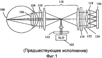
На фиг.1 показан типичный датчик Шака-Гартмана предшествующей техники, применяемый для измерения аберрации глаза. В качестве источника света здесь обычно используется SLD (сверхлюминесцирующий диод) 102, а свет подают на относительно малый участок сетчатки 108 через оптическую систему глаза (включающую роговицу 104 и хрусталик 106). Рассеянный свет от сетчатки 108 проходит через оптическую изображающую систему глаза (включающую роговицу 104 и хрусталик 106) и выходит из зрачка в виде аберрационного волнового фронта 110. Для подавления интерференции от света, отражаемого роговицей 104 и другими оптическими поверхностями сопряжения, такими как элементы хрусталика 106, иными, чем сетчатка 108, падающий относительно узкий световой пучок обычно поляризуют с помощью первого поляризатора 112 в первом направлении. Исходя из того, что свет, рассеиваемый сетчаткой, является намного более деполяризованным, свет, рассеиваемый сетчаткой, обычно измеряют во втором ортогональном направлении поляризации с помощью второго ортогонального анализатора 114.Figure 1 shows a typical prior art Shack-Hartmann sensor used to measure eye aberration. Here, SLD (superluminescent diode) 102 is usually used as the light source, and light is supplied to a relatively small portion of the
Чтобы увеличить или уменьшить или просто перенести аберрационный волновой фронт на решетку элементарных линз 118, можно использовать релейную оптическую систему, например, 116, состоящую из набора линз. Если решетка элементарных линз 118 находится в сопряженной плоскости зрачка (плоскость изображения зрачка), волновой фронт в плоскости элементарной линзы будет идентичным или будет увеличенной или уменьшенной модификацией формы волнового фронта в плоскости зрачка. Решетка элементарных линз 118 тогда образует решетку изображений пятен в камере 120 на ПЗС. Если глаз является совершенной оптической системой, волновой фронт в плоскости решетки элементарных линз должен быть совершенно плоским (как показано сплошной прямой линией 122), а равномерно распределенная решетка пятен изображения должна регистрироваться в камере 120 на ПЗС, расположенной в фокальной плоскости решетки элементарных линз.To increase or decrease or simply transfer the aberration wavefront to the array of
С другой стороны, если глаз не обладает совершенством, волновой фронт 124 на решетке элементарных линз не должен быть длиннее совершенно плоского фронта и будет иметь неправильную искривленную форму. Следовательно, изображения пятен в камере 120 на ПЗС будут отклоняться от местоположений, соответствующих случаю отсутствия аберрации. Благодаря обработке данных о положении пятен изображения в камере 120 на ПЗС можно определить как аберрацию низшего порядка, так и аберрацию высшего порядка для глаза (см., например, J.Liang и др., 1994, "Объективные измерения волновых аберраций человеческого глаза с помощью датчика волновых фронтов Гартмана-Шака ", J.Opt.Soc.Am.A-11,1949-1957).On the other hand, if the eye is not perfect, the
Хотя датчик волнового фронта может измерять аберрацию как низшего, так и высшего порядка в оптической системе формирования изображения, для нестатической изображающей системы, например, человеческого глаза, установлено, что только значения аберрации низшего порядка, соответствующие сфероцилиндрическому отклонению, измеренному для центральной части глаза, являются относительно приемлемыми (см., например, Ginis HS и др. "Непостоянство измерений аберрации волнового фронта при небольших размерах зрачка с использованием клинического измерителя аберрации Шака-Гартмана", ВМС Ophthalmol 2004 Feb. 11; 4:1).Although the wavefront sensor can measure both lower and higher order aberration in an optical imaging system, for a non-static imaging system, such as the human eye, it has been found that only the lower order aberration values corresponding to the spherical cylindrical deviation measured for the central part of the eye are relatively acceptable (see, for example, Ginis HS et al. "The inconsistency of wavefront aberration measurements at small pupil sizes using clinical measurements To aberration Shack-Hartmann "Navy Ophthalmol 2004 Feb. 11; 4: 1).
На практике для большинства измерений и коррекции аберрации глаза, а также для большинства оптических изображающих систем глазного дна оптические аберрации, которые необходимо измерить и скорректировать, являются сфероцилиндрическими отклонениями (также называемыми дефокусированием или астигматизмом). Всем специалистам в данной области хорошо известно, что эти аберрации можно измерять, используя небольшое количество фронтов парциальных волн по эпициклу (annular ring) падающего волнового фронта. В этом случае значительная часть решеток детекторов ПЗС оказывается ненужной. Ради экономии некоторое количество (обычно 8 или 16) счетверенных детекторов может располагаться по эпициклу аберрационного волнового фронта для выполнения измерений только этих фронтов парциальных волн (см., например, US 4141652, который вместе со всеми другими материалами, использованными при экспертизе заявки, вводится сюда полностью в качестве ссылочного материала для данной патентной заявки).In practice, for most measurements and correction of eye aberration, as well as for most optical imaging of the fundus, the optical aberrations that need to be measured and corrected are spherical cylindrical deviations (also called defocusing or astigmatism). All specialists in this field are well aware that these aberrations can be measured using a small number of partial wave fronts along the annular ring of the incident wave front. In this case, a significant part of the CCD detector arrays is unnecessary. For the sake of economy, a certain number (usually 8 or 16) of quad detectors can be located on the epicycle of the aberration wavefront to measure only these partial wave fronts (see, for example, US 4141652, which, together with all other materials used in the examination of the application, is introduced here fully as reference material for this patent application).
Однако при таком расположении необходимо еще использовать большое количество счетверенных детекторов, которые, хотя и совокупно менее дороги, чем камера на ПЗС большой площади, но все еще более дороги, чем одиночный счетверенный детектор. Вдобавок юстировка большого количества счетверенных детекторов также намного более сложна, чем юстировка одиночного счетверенного детектора.However, with this arrangement, it is still necessary to use a large number of quad detectors, which, although collectively less expensive than a large-area CCD camera, are still more expensive than a single quad detector. In addition, adjusting a large number of quad detectors is also much more complicated than aligning a single quad detector.
Краткое описание чертежейBrief Description of the Drawings
Фиг.1 - образцовый датчик Шака-Гартмана предшествующей техники, применяемый для измерения аберрации глаза.Figure 1 - an exemplary Shack-Hartmann sensor of the prior art, used to measure eye aberration.
Фиг.2 - образцовая принципиальная схема примера осуществления датчика последовательности волновых фронтов.Figure 2 is an exemplary schematic diagram of an example implementation of a wavefront sequence detector.
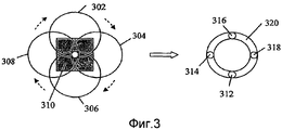
Фиг.3 - относительное радиальное и азимутальное смещение реплицированного волнового фронта в 4 симметричных положениях, которые соответствуют 4 фронтам парциальных волн, выбранных апертурой по эпициклу первоначального волнового фронта.Figure 3 - the relative radial and azimuthal displacement of the replicated wavefront in 4 symmetrical positions, which correspond to 4 fronts of partial waves selected by the aperture on the epicycle of the original wavefront.
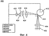
Фиг.4 - альтернативный пример осуществления датчика последовательности волновых фронтов, в котором отраженный пучок направляют в сторону с помощью сканирующего зеркала вместо его первоначального направления обратно.Figure 4 is an alternative embodiment of a wavefront sequence sensor in which a reflected beam is directed to the side with a scanning mirror instead of its original direction back.
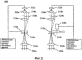
Фиг.5 - другой альтернативный пример осуществления датчика последовательных волновых фронтов, в котором применяется сканирующее устройство пропускаемого оптического пучка.5 is another alternative embodiment of a sequential wavefront sensor in which a transmitting optical beam scanning device is used.
Фиг.6 - еще один альтернативный пример осуществления датчика последовательных волновых фронтов, в котором в траекторию оптического пучка может быть последовательно включено некоторое количество параллельных оптических блоков различной необходимой пространственной ориентации, чтобы смещать пучок в поперечном направлении.6 is another alternative embodiment of a sequential wavefront sensor in which a plurality of parallel optical units of different spatial orientations can be sequentially included in the path of an optical beam to bias the beam in the transverse direction.
Фиг.7 - фотоприемник с четырьмя светочувствительными участками А, В, С и D и пятно изображения на счетверенном детекторе для нормально падающего фронта парциальной волны и неперпендикулярно падающего волнового фронта.7 is a photodetector with four photosensitive sections A, B, C and D and an image spot on a quad detector for a normally incident partial wave front and a non-perpendicular incident wave front.
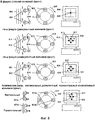
Фиг.8 - типичные случаи удовлетворительного фокусирования, дефокусирования и астигматизма с соответствующей картиной пятна изображения на счетверенном детекторе после линзы фокусирования фронта парциальной волны, а также последовательное перемещение соответствующих позиций центроида при показе на мониторе.Fig - typical cases of satisfactory focusing, defocusing and astigmatism with the corresponding picture of the image spot on the quad detector after the lens focusing the front of the partial wave, as well as sequential movement of the corresponding positions of the centroid when displayed on the monitor.
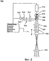
Фиг.9 - система, в которой оптический элемент высокоскоростного регулирования фокуса приводится высокоскоростным двигателем в режиме регулирования с обратной связью, чтобы удержать оптическую систему в сфокусированном состоянии.9 is a system in which an optical element of a high-speed focus control is driven by a high-speed motor in a closed-loop control mode to keep the optical system in focus.
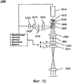
Фиг.10 - система, в которой условие вращения траектории центроида можно использовать как обратную связь в системе регулирования по замкнутому контуру для поворота двух цилиндрических линз с целью регулирования и корректирования астигматизма.Figure 10 is a system in which the rotation condition of the centroid trajectory can be used as feedback in a closed-loop control system for rotating two cylindrical lenses in order to regulate and correct astigmatism.
Подробное описание изобретенияDETAILED DESCRIPTION OF THE INVENTION
Теперь обратимся к подробностям различных вариантов осуществления данного изобретения. Примеры этих вариантов осуществления показаны на прилагаемых чертежах. В то время как изобретение будет описано в связи с этими примерами, должно быть понятно, что нет намерения ограничивать объем изобретения какими-либо вариантами осуществления. Наоборот, предполагается охватить альтернативы, модификации и эквиваленты, которые могут быть включены в пределы сущности и объема, определяемые прилагаемой формулой. В следующем описании с целью обеспечения полного понимания различных вариантов осуществления разъясняются многочисленные специфические подробности. Однако данное изобретение может быть осуществлено на практике без некоторых или даже без всех этих специфических подробностей. В других случаях хорошо известные технологические операции не описываются подробно, чтобы не затемнять сущность данного изобретения.Now turn to the details of various embodiments of the present invention. Examples of these embodiments are shown in the accompanying drawings. While the invention will be described in connection with these examples, it should be understood that there is no intention to limit the scope of the invention to any embodiments. On the contrary, it is intended to cover alternatives, modifications, and equivalents that may be included within the spirit and scope of the appended claims. In the following description, numerous specific details are set forth in order to provide a thorough understanding of the various embodiments. However, the present invention may be practiced without some or even all of these specific details. In other cases, well-known process steps are not described in detail so as not to obscure the essence of the present invention.
В данном изобретении предлагается датчик фронтов последовательных волн, содержащий модуль сканирования светового пучка, фокусирующую линзу фронта парциальной волны, детектор с несколькими светочувствительными участками и процессор для вычисления последовательно получаемых центроидов фокусируемого светового пятна от фронтов парциальных волн для определения аберрации падающего волнового фронта. В этом варианте осуществления изобретения фокусирующая линза фронта парциальной волны и детектор закреплены неподвижно, а падающий пучок подвергается сканированию модулем сканирования светового пучка, чтобы последовательно спроецировать различные части волнового фронта из падающего пучка или реплики волнового фронта на линзу фокусирования фронта парциальной волны и детектор. Процессор может быть компьютером или программируемой электронной платой, которую можно использовать для вычисления следа центроида или картины на плоскости х-у.The present invention provides a sequential wavefront sensor, comprising a light beam scanning module, a focusing partial wave front lens, a detector with several photosensitive portions, and a processor for calculating sequentially obtained centroids of a focused light spot from the partial wave fronts to determine the aberration of the incident wavefront. In this embodiment, the partial wave front focusing lens and the detector are fixedly mounted, and the incident beam is scanned by the light beam scanning module to sequentially project different portions of the wave front from the incident beam or wavefront replica onto the partial wave front focusing lens and the detector. The processor may be a computer or a programmable electronic circuit board that can be used to calculate the trace of a centroid or picture on the xy plane.
На фиг.2 показана образцовая принципиальная схема осуществления датчика 200 волнового фронта. Линейно поляризованный падающий пучок света, имеющий волновой фронт 202, фокусируется первой линзой 204. Сфокусированный пучок проходит через поляризационный светоделитель (PBS) 206, который располагается таким образом, что его угол поляризации при сквозном проходе совпадает с углом поляризации входящего пучка. В результате через светоделитель 206 будет проходить линейно поляризованный сходящийся пучок. За светоделителем 206 располагается четвертьволновая пластинка 208 с осью наибольшей скорости распространения света, ориентированной таким образом, что после прохождения через четвертьволновую пластинку 208 появляется пучок с круговой поляризацией. За четвертьволновой пластинкой 208 и непосредственно перед сканирующим зеркалом 212 располагается точечная диафрагма 210, которая служит для подавления света, не происходящего непосредственно от интересующего нас волнового фронта светового пучка.Figure 2 shows an exemplary circuit diagram of the implementation of the sensor 200 wavefront. A linearly polarized incident light beam having a wavefront 202 is focused by the first lens 204. The focused beam passes through a polarization beam splitter (PBS) 206, which is positioned so that its polarization angle through the passage coincides with the polarization angle of the incoming beam. As a result, a linearly polarized converging beam will pass through the beam splitter 206. Behind the beam splitter 206 there is a quarter-wave plate 208 with an axis of the highest speed of light propagation, oriented in such a way that after passing through the quarter-wave plate 208, a beam with circular polarization appears. Behind the quarter-wave plate 208 and directly in front of the scanning mirror 212, there is a point diaphragm 210, which serves to suppress light not originating directly from the wavefront of the light beam of interest to us.
Падающий сходящийся пучок после прохождения через точечную диафрагму 210 фокусируется на поверхности отражения наклонного сканирующего зеркала 212, которое установлено на валу двигателя 214. Световой пучок, отражаемый зеркалом, является расходящимся, причем его основной центральный луч изменяет направление, которое зависит от угла наклона сканирующего зеркала 212 и углового положения двигателя 214. Ожидается, что отраженный пучок дополнительно подвергается круговой поляризации, но направление вращения круговой поляризации будет изменяться от "слева направо" до "справа налево". Однако при прохождении через четвертьволновую пластинку 208 второй раз на своем обратном пути пучок снова становится линейно поляризованным, но направление его поляризации смещается перпендикулярно относительно первоначального входящего пучка. Следовательно, при поляризационном светоделителе 206 возвратный пучок будет преимущественно отражаться влево, как показано пунктирными линиями на фиг.2.The incident converging beam after passing through the pinhole 210 is focused on the reflection surface of the inclined scanning mirror 212, which is mounted on the shaft of the engine 214. The light beam reflected by the mirror is diverging, and its main central beam changes direction, which depends on the angle of inclination of the scanning mirror 212 and angular position of the engine 214. It is expected that the reflected beam is further subjected to circular polarization, but the direction of rotation of the circular polarization will change from "left" to "right to left". However, when passing through the quarter-wave plate 208 a second time on its return path, the beam again becomes linearly polarized, but the direction of its polarization shifts perpendicular to the original incoming beam. Therefore, with the polarization beam splitter 206, the return beam will mainly be reflected to the left, as shown by dashed lines in FIG.
Вторая линза 216 располагается слева рядом со светоделителем 206, чтобы коллимировать отраженный расходящийся пучок и производить реплику первоначального входящего фронта волны. Вследствие наклона сканирующего зеркала реплицированный волновой фронт сдвигается в поперечном направлении. За второй линзой 216 и непосредственно перед фокусирующей линзой 220 фронта парциальной волны располагается апертура 218 для выбора небольшой части реплицированного волнового фронта. Линза 220 фокусирует выбранный фронт парциальной волны на позиционном чувствительном устройстве 222, которое используется для определения центроида сфокусированного светового пятна, происходящего от последовательно выбираемых фронтов парциальных волн. С помощью вращения двигателя 214 и изменения угла наклона сканирующего зеркала 212 в пошаговом режиме можно отрегулировать величину радиального и азимутального сдвига реплицированного фронта волны таким образом, что любая часть реплицированного фронта волны может быть выбрана для прохождения через апертуру 218 последовательно. В результате можно получить характеристику всего волнового фронта первоначального входящего пучка как в случае применения обычного датчика волнового фронта Гартмана-Шака с тем исключением, что центроид каждого фронта парциальной волны теперь получается последовательно, а не параллельно.A second lens 216 is located on the left next to the beam splitter 206 in order to collimate the reflected diverging beam and to replicate the initial incoming wave front. Due to the tilt of the scanning mirror, the replicated wavefront shifts in the transverse direction. Behind the second lens 216 and immediately before the focusing lens 220 of the partial wave front, there is an aperture 218 for selecting a small portion of the replicated wave front. Lens 220 focuses the selected front of the partial wave on the position sensitive device 222, which is used to determine the centroid of the focused light spot originating from successively selected fronts of partial waves. By rotating the motor 214 and changing the angle of the scanning mirror 212 in a step-by-step mode, the radial and azimuthal shift of the replicated wave front can be adjusted so that any part of the replicated wave front can be selected to pass through the aperture 218 in series. As a result, it is possible to obtain a characteristic of the entire wavefront of the initial incoming beam as in the case of the use of a conventional Hartmann-Shack wavefront sensor with the exception that the centroid of each front of the partial wave is now obtained in series, and not in parallel.
В другом примере осуществления угол наклона сканирующего зеркала является постоянным, а двигатель вращается в многоступенчатом режиме непрерывно. В результате будет выбрано и охарактеризовано только установленное количество фронтов парциальных волн по эпициклу волнового фронта. Этот режим сканирования чрезвычайно удобен для определения сфероцилиндрического отклонения или дефокусирования и астигматизма первоначального волнового фронта, как указывалось в предшествующем разделе. На фиг.3 показан радиальный и азимутальный сдвиг относительно апертуры 310 реплицированных волновых фронтов 302, 304, 306 и 308 в 4 симметричных позициях остановливаемого двигателя на каждом обороте, причем эти волновые фронты соответствуют 4 фронтам парциальных волн 312, 314, 316, 318, выбираемым с помощью апертуры 310 по эпициклу 320 первоначального волнового фронта.In another embodiment, the tilt angle of the scanning mirror is constant, and the engine rotates continuously in a multi-stage mode. As a result, only the set number of partial wave fronts will be selected and characterized along the wavefront epicycle. This scanning mode is extremely convenient for determining the spherical cylindrical deviation or defocusing and astigmatism of the initial wavefront, as indicated in the previous section. Figure 3 shows the radial and azimuthal shift relative to the
Понятно, что без отступления от объема данного изобретения сюда можно внести многочисленные изменения, касающиеся применяемых компонентов. Например, четвертьволновая пластинка может быть четвертьволновой пластинкой ненулевого порядка и ее можно заменить ячейкой Фарадея, которая будет вращать угол поляризации возвратного пучка до прямого. Кроме того, входящий пучок может не быть линейно поляризованным, а тип светоделителя нет необходимости ограничивать поляризационным светоделителем. Может быть использован обычный оптический светоделитель, и в таком случае четвертьволновая пластинка или ячейка Фарадея может быть удалена. Хотя световой кпд на детекторе будет при этом понижаться, это необязательно повлияет на характеристику датчика волнового фронта, пока имеется достаточная мощность оптического излучения, передаваемая на детектор.It is understood that, without departing from the scope of the present invention, numerous changes can be made here regarding the components used. For example, a quarter-wave plate can be a quarter-wave plate of a nonzero order and can be replaced by a Faraday cell, which will rotate the polarization angle of the return beam to a straight line. In addition, the incoming beam may not be linearly polarized, and there is no need to limit the type of beam splitter to a polarizing beam splitter. A conventional optical beam splitter can be used, in which case the quarter-wave plate or Faraday cage can be removed. Although the light efficiency at the detector will decrease, this will not necessarily affect the characteristics of the wavefront sensor as long as there is sufficient optical power transmitted to the detector.
Позиционное чувствительное устройство (PSD) является датчиком, применяемым для определения местоположения центроида светового пятна. Позиционное чувствительное устройство может быть, но не ограничиваться счетверенным детектором, PSD-датчиком или детектором, имеющим многочисленные светочувствительные участки, например, решеткой детекторов 2D малой площади. Такие детекторы включают площадной индикатор на ПЗС и площадной индикатор КМОП. Применяемые линзы, включающие 204, 216, 220, не должны ограничиваться одиночной линзой каждая и могут быть комбинацией линз, что хорошо известно всем специалистам в данной области. Апертура перед фокусирующей линзой фронта парциальной волны может быть удалена, если эта фокусирующая линза является столь малой как одиночная элементарная линза. Иными словами, апертура предпочтительно необходима и целью апертуры является выбор малой части волнового фронта для фокусирования на детекторе, когда фокусирующая линза, применяемая позади апертуры, является относительно большой. Апертура необязательно ограничивается конфигурацией постоянного размера. Апертура переменного размера во время работы позволяет выбор чувствительности и разрешающей способности.A position sensitive device (PSD) is a sensor used to determine the location of a centroid of a light spot. A positional sensitive device can be, but is not limited to, a quad detector, a PSD sensor, or a detector having multiple photosensitive regions, for example, a array of small-area 2D detectors. Such detectors include a CCD area indicator and a CMOS area indicator. Used lenses, including 204, 216, 220, should not be limited to a single lens each and can be a combination of lenses, which is well known to all specialists in this field. The aperture in front of the focusing lens of the partial wave front can be removed if this focusing lens is as small as a single elementary lens. In other words, the aperture is preferably necessary and the purpose of the aperture is to select a small portion of the wavefront to focus on the detector when the focusing lens used behind the aperture is relatively large. The aperture is not necessarily limited to a constant size configuration. A variable size aperture during operation allows the selection of sensitivity and resolution.
Вдобавок линзу фокусирования фронта парциальной волны можно заменить любым оптическим элементом, который способен выполнять функцию фокусирования, например, линзой с изменяющимся показателем преломления; может быть также использовано фокусирующее зеркало. Также количество остановок при каждом обороте двигателя нет необходимости ограничивать четырьмя, оно может быть любым количеством. Кроме того, двигатель может вращаться непрерывно, а источник света может быть короткоимпульсным с различной длительностью зажигания. Угол наклона сканирующей линзы также может динамически изменяться в реальном времени, так что могут выбираться различные части эпицикла волнового фронта. Фактически, хотя мы и применяем термин "наклонное зеркало ", следует заметить, что этот термин также включает и случай нулевого угла наклона зеркала, то есть падающий пучок может быть перпендикулярным к зеркалу, так что отраженный пучок будет соосным с пучком падающим при направлении центральной части первоначального волнового фронта на детектор.In addition, the focusing lens of the partial wave front can be replaced by any optical element that is able to perform the focusing function, for example, a lens with a variable refractive index; a focusing mirror can also be used. Also, the number of stops at each revolution of the engine does not need to be limited to four, it can be any number. In addition, the engine can rotate continuously, and the light source can be short-pulse with different ignition times. The tilt angle of the scanning lens can also be dynamically changed in real time, so that different parts of the wavefront epicycle can be selected. In fact, although we use the term “tilted mirror”, it should be noted that this term also includes the case of a tilt angle of the mirror, that is, the incident beam can be perpendicular to the mirror, so that the reflected beam will be coaxial with the beam incident in the direction of the central part initial wavefront at the detector.
Порядок последовательности поворота двигателя и наклона сканирующего зеркала может также быть обратным или смешанным, так что выбор фронтов парциальных волн может происходить в любой желаемой последовательности. Кроме того, сканирующее зеркало и двигатель могут быть заменены (но без ограничения такой заменой) зеркалом с микроэлектромеханической системой, которое в настоящее время предлагается рынком, или любым другим деформируемым зеркалом, которое способно изменять направление отражаемого светового пучка. Достоинством зеркала с микроэлектромеханической системой является то, что оно имеет относительно высокочастотную характеристику вследствие малой массы подвижных частей зеркала, в результате чего может быть достигнута высокая скорость обнаружения фронтов последовательных волн. Вдобавок угол наклона зеркала с микроэлектромеханической системой можно легко регулировать.The order of the rotation sequence of the engine and the tilt of the scanning mirror can also be reversed or mixed, so that the selection of the fronts of the partial waves can occur in any desired sequence. In addition, the scanning mirror and the engine can be replaced (but not limited to such a replacement) by a mirror with a microelectromechanical system, which is currently offered by the market, or any other deformable mirror that can change the direction of the reflected light beam. The advantage of a mirror with a microelectromechanical system is that it has a relatively high-frequency characteristic due to the small mass of the moving parts of the mirror, as a result of which a high detection speed of successive wave fronts can be achieved. In addition, the angle of inclination of the mirror with a microelectromechanical system can be easily adjusted.
Понятно, что без отступления от объема данного изобретения возможны также многие изменения, касающиеся конфигурации системы. Например, нет никакой необходимости в отражении волнового фронта сначала в обратном направлении, а затем отклонении пучка в сторону.It is understood that, without departing from the scope of the present invention, many changes are also possible regarding the configuration of the system. For example, there is no need to reflect the wavefront first in the opposite direction, and then deflect the beam to the side.
В качестве альтернативы сканирующее зеркало можно также заменить многоэлементным фацетным барабанным зеркалом 412, каждая отражающая поверхность которого имеет желаемую пространственную ориентацию, так что, когда каждая отражающая поверхность поворачивается в определенное положение в пошаговом или непрерывном режиме, сходящийся падающий пучок отражается вместе с центральным основным лучом, располагаясь в виде конуса. На фиг.4 показан схематический вид поперечного сечения такой конфигурации 400, в которой отраженный пучок смещается в поперечном направлении вверх. Следует заметить, что отраженный пучок также может смещаться вниз, влево, вправо или в любом азимутальном направлении на любую величину радиального смещения. Это происходит потому, что многоэлементное фацетное барабанное зеркало 412 не является симметричным многогранником, и когда каждая поверхность перемещается в положение для отражения падающего сходящегося пучка, он будет отражать пучок под другим пространственным углом, так что необходимая часть реплицированного волнового фронта выбирается апертурой для фокусирования на детекторе.Alternatively, the scanning mirror can also be replaced by a multi-facet
Вдобавок на траектории входящего света перед многоэлементным фацетным зеркалом может опять-таки располагаться точечная диафрагма для отклонения света, приходящего не от падающего пучка желаемого направления или местоположения. Заметим, что та же самая конфигурация может быть осуществлена путем применения зеркала с микроэлектромеханической системой вместо многоэлементного фацетного зеркала, которое предоставит все преимущества, названные выше. Также следует заметить, что многоэлементное фацетное барабанное зеркало может иметь такую ориентацию фацетов, что при непрерывном вращении барабана в пошаговом режиме выбирается большое количество фронтов парциальных волн по эпициклу волнового фронта для фокусирования на детекторе.In addition, a point diaphragm can again be located on the path of the incoming light in front of the multi-facet facet mirror to deflect the light coming not from the incident beam of the desired direction or location. Note that the same configuration can be accomplished by using a mirror with a microelectromechanical system instead of a multi-facet facet mirror, which will provide all the advantages mentioned above. It should also be noted that a multi-facet facet drum mirror can have a facet orientation such that with continuous rotation of the drum in a step-by-step mode, a large number of partial wave fronts are selected along the wavefront epicycle to focus on the detector.
В качестве другой альтернативы система также может быть полностью скомпонована для режима работы в пропускаемом свете вместо режима работы в отраженном свете. На фиг.5 показана конфигурация, в которой многоэлементное фацетное барабанное зеркало заменено устройством сканирования пропускаемого оптического пучка 512а и 512b. В продаже имеется большое количество различных сканирующих устройств пропускаемого пучка, например, акустооптический модулятор, электрооптическое или магнитооптическое устройство сканирования пучка и устройство сканирования пучка на жидких кристаллах, которые представлены под 512а. В этом случае сканирующее устройство должно обладать способностью сканирования пучка, сфокусированного или несфокусированного, в зависимости от размеров окна пропускающего сканирующего устройства, чтобы последовательно направлять определенное количество желаемых частей волнового фронта для характеризации.As another alternative, the system can also be fully configured for a transmitted light mode instead of a reflected light mode. FIG. 5 shows a configuration in which a multi-facet facet drum mirror is replaced by a scanning optical
В качестве альтернативы для этой цели можно также использовать многоэлементный клиновидный секторный диск 512b. Понятно, что, как это описывалось для многоэлементного фацетного барабанного зеркала в случае отражения, многоэлементный клиновидный секторный диск 512b для случая пропускания также должен быть несимметричным диском в том смысле, что при повороте одного из секторов клина в положение отражения пучка сфокусированного или несфокусированного, угол клина будет определять возникающее направление пучка и, следовательно, часть волнового фронта, которая будет выбрана апертурой 518b. Каждый сектор клина должен иметь различную ориентацию угла клина, чтобы дать возможность получения характеристики последовательности желаемых фронтов парциальных волн. Заметим, что при малых размерах окна пропускающего устройства сканирования падающий пучок должен быть сфокусирован на месте расположения пропускающего устройства сканирования, и в этом случае первая линза должна быть использована для фокусирования падающего оптического пучка, а вторая линза должна быть использована для коллимирования пропускаемого пучка, чтобы произвести реплику входящего волнового фронта, который смещается в пространстве в поперечном направлении.Alternatively, a multi-piece wedge-shaped
В другом варианте осуществления данного изобретения концепция последовательно смещаемого в поперечном направлении волнового фронта падающего пучка дополнительно расширяется, включая случай поперечного смещения падающего пучка, в котором падающий пучок не фокусируют, а затем повторно коллимируют. Вместо этого падающий пучок подвергают поперечному смещению, чтобы направить желаемую часть волнового фронта на апертуру (618а, 618b). Преимуществом такой схемы является то, что требуется меньше оптических элементов и, следовательно, модуль сканирования света может быть значительно упрощен. На фиг.6 показан пример, в котором на траектории оптического пучка с целью поперечного смещения последнего может быть последовательно установлено некоторое количество параллельных оптических блоков (612а, 612b) с различной желаемой пространственной ориентацией.In another embodiment of the present invention, the concept of a sequentially shifted transverse wavefront of the incident beam is further expanded to include the case of transverse bias of the incident beam in which the incident beam is not focused and then re-collimated. Instead, the incident beam is subjected to lateral displacement in order to direct the desired part of the wavefront to the aperture (618a, 618b). An advantage of this arrangement is that fewer optical elements are required, and therefore, the light scanning module can be greatly simplified. FIG. 6 shows an example in which a number of parallel optical units (612a, 612b) with different desired spatial orientations can be sequentially mounted on the path of the optical beam to laterally displace the latter.
В качестве альтернативы пропускающее сканирующее устройство оптического пучка может быть многоэлементным фацетным пропускающим многогранником, который вращается шаг за шагом, преграждая путь оптического пучка таким образом, чтобы последовательно смещать пучок в поперечном направлении. Заметим также, что поперечное смещение оптического пучка не обязательно должно выполняться механическими средствами. Например, для поперечного смещения пучка можно использовать жидкокристаллическую ячейку, электрооптическую ячейку или магнитнооптическую ячейку; в этих случаях изменение эффективного показателя преломления ячейки будет изменять величину поперечного смещения пучка. Как и в случае отражающего сканирующего устройства оптического пучка, пропускающее сканирующее устройство оптического пучка может обеспечивать возможность выбора определенного количества фронтов парциальных волн по эпициклу волнового фронта для фокусирования на детекторе с целью обнаружения аберрации -дефокусирования и астигматизма.Alternatively, the transmittance scanning device of the optical beam can be a multi-facet transmittance transmitting polyhedron that rotates step by step, blocking the path of the optical beam so as to sequentially shift the beam in the transverse direction. We also note that the transverse displacement of the optical beam does not have to be performed by mechanical means. For example, for a transverse beam displacement, a liquid crystal cell, an electro-optical cell, or a magneto-optical cell can be used; in these cases, a change in the effective refractive index of the cell will change the magnitude of the transverse displacement of the beam. As in the case of a reflective scanning device of an optical beam, a transmission scanning device of an optical beam can provide the ability to select a certain number of partial wave fronts on the wavefront epicycle to focus on the detector in order to detect aberration-defocusing and astigmatism.
Вышеописанный датчик волнового фронта можно использовать для большого количества применений. Первым и главным применением является самонастраивающаяся оптика, в которой измеренный искаженный волновой фронт можно скомпенсировать в реальном времени, используя устройство для компенсации волнового фронта, например, решетку деформируемых зеркал. В этом случае скорость сканирования пучка должна быть относительно высока и, следовательно, предпочтительно использовать высокоскоростные устройства сканирования пучка или сдвигающие устройства, такие как зеркало с микроэлектромеханической системой и электрооптические или магнитооптические ячейки.The wavefront sensor described above can be used for a large number of applications. The first and main application is self-tuning optics in which the measured distorted wavefront can be compensated in real time using a device for compensating the wavefront, for example, a grating of deformable mirrors. In this case, the beam scanning speed should be relatively high and, therefore, it is preferable to use high-speed beam scanning devices or biasing devices, such as a mirror with a microelectromechanical system and electro-optical or magneto-optical cells.
Вторым главным применением вышеописанного варианта осуществления является автофокусирование и/или коррекция астигматизма. Благодаря тому что для заключения о дефокусировании и астигматизме изображающей системы, такой как человеческий глаз, необходимо охарактеризовать только небольшое количество (например, 8) фронтов парциальных волн по эпициклу, нет необходимости применения модуля сканирования оптического пучка с высокочастотной характеристикой и соответственно будет достаточно сканирующего устройства с низкой стоимостью, например, наклонного зеркала, установленного на шаговом двигателе, как показано на фиг.4. Например, вышеописанный датчик волнового фронта может быть применен в фундус-камере для дефокусирования и/или коррекции астигматизма изображающей системы глаза в реальном времени, как описано в US 6361167 и US 6685317, так что может быть получено фундус-изображение с высокой разрешающей способностью.A second main application of the above embodiment is autofocusing and / or astigmatism correction. Due to the fact that in order to conclude that the imaging system, such as the human eye, is defocused and astigmatism, it is necessary to characterize only a small number (for example, 8) of the partial wave fronts along the epicycle, there is no need to use an optical beam scanning module with a high-frequency characteristic and, accordingly, a scanning device with low cost, for example, an inclined mirror mounted on a stepper motor, as shown in Fig.4. For example, the wavefront sensor described above can be used in a fundus camera to defocus and / or correct the astigmatism of an imaging eye system in real time, as described in US 6361167 and US 6685317, so that a fundus image with high resolution can be obtained.
Другой отличительной чертой вышеописанного датчика волнового фронта является то, что при использовании для характеризации только дефокусирования и/или астигматизма будет достаточно счетверенного детектора, а его выходной сигнал можно обработать для получения последовательной записи или картины, которая может быть показана на мониторе для выявления в реальном времени следующего: находится ли оптическая изображающая система перед датчиком волнового фронта в фокусе или нет; как далеко находится этот фокус; является ли дефокусирование конвергентным или дивергентным, какова величина астигматизма, а также оси астигматизма.Another distinguishing feature of the wavefront sensor described above is that when using only defocusing and / or astigmatism to characterize, a quad detector will be sufficient, and its output signal can be processed to obtain a sequential recording or picture that can be displayed on the monitor for real-time detection of the following: whether the optical imaging system is in focus in front of the wavefront sensor or not; how far this focus is; whether defocusing is convergent or divergent, what is the magnitude of astigmatism, as well as the axis of astigmatism.
Предположим, что применяется счетверенный детектор 702 с четырьмя светочувствительными участками А, В, С и D, как показано на фиг.7. Если фронт парциальной волны падает под прямым углом относительно линзы фокусирования фронта парциальной волны, пятно 704 изображения на счетверенном детекторе будет находиться в центре и четыре светочувствительных участка будут получать одно и то же количество света, причем каждый участок будет вырабатывать сигнал одной и той же величины. С другой стороны, если фронт парциальной волны отклоняется от нормального падения на какой-то угол наклона (скажем, принимает правое верхнее направление), пятно изображения на счетверенном детекторе при этом будет образовываться в стороне от центра (перемещаясь в правый верхний квадрант, как показано пятном 706 изображения). Отклонение (х, у) центроида от центра (х=0, у=0) может быть выражено следующими уравнениями:Assume that a

где А, В, С и D обозначают величину сигнала каждого соответствующего светочувствительного участка счетверенного детектора, а знаменатель (A+B+C+D) используется для нормализации измерения, так что может быть сведено на нет влияние изменений интенсивности оптического источника.where A, B, C and D denote the signal value of each respective photosensitive portion of the quad detector, and the denominator (A + B + C + D) is used to normalize the measurement, so that the influence of changes in the intensity of the optical source can be negated.
Когда определенное количество симметричных фронтов парциальных волн (например, 4, 8 или 16) по эпициклу оптического пучка последовательно проецируется (например, в направлении часовой стрелки) на фокусирующую линзу фронта парциальной волны и счетверенный детектор, отклонение центроида, как показано символами (х,у) уравнения (1), от центра счетверенного детектора будет создавать картину на плоскости х-у, которую можно показать на мониторе, а также обработать в цифровой форме, чтобы представить состояние дефокусирования и астигматизма.When a certain number of symmetrical partial wave fronts (for example, 4, 8, or 16) are projected sequentially (for example, in the clockwise direction) onto the focusing lens of the partial wave front and the quadruple detector, the centroid deflection as shown by the symbols (x, y ) of equation (1), from the center of the quad detector will create a picture on the xy plane, which can be shown on the monitor, and also processed digitally to represent the state of defocusing and astigmatism.
На фиг.8 показаны типичные случаи удовлетворительного фокусирования, дефокусирования и астигматизма, соответствующие картины пятен изображения на счетверенном детекторе позади линзы фокусирования фронта парциальной волны, а также последовательное перемещение соответствующих положений центроида при показе на мониторе. Заметим, что вместо вытаскивания (drawing) некоторого количества подлежащих проецированию волновых фронтов с помощью различных фронтов парциальных волн на одни и те же линзы фокусирования фронтов парциальных волн и счетверенный детектор, мы взяли эквивалентное представление, показанное на фиг.3, в котором определенное количество фронтов парциальных волн выстраивается вдоль (are drawn around) того же самого эпицикла и соответственно определенное количество счетверенных детекторов выстраивается вдоль того же эпицикла, чтобы представить случай сканирования различных частей волнового фронта на линзу фокусирования фронтов парциальных волн и одиночный счетверенный детектор.On Fig shows typical cases of satisfactory focusing, defocusing and astigmatism, the corresponding pattern of image spots on a quad detector behind the focus lens of the front of the partial wave, as well as sequential movement of the corresponding positions of the centroid when displayed on the monitor. Note that instead of drawing out a certain number of wave fronts to be projected using different fronts of partial waves onto the same focusing lenses of the partial wave fronts and the quad detector, we took the equivalent representation shown in Fig. 3, in which a certain number of fronts partial waves line up around (are drawn around) the same epicycle, and accordingly a certain number of quad detectors line up along the same epicycle to represent a case of nirovaniya different parts of the wave front on the lens focusing the partial wave fronts and a single quad detector.
Предположим, что мы начинаем сканирование по эпициклу волнового фронта с фронта верхней парциальной волны и перемещаемся по часовой стрелке к фронту второй парциальной волны вправо и т.д., как показано стрелкой 809. На фиг.8 можно видеть, что, если фронт волны является плоской волной 801, означая тем самым, что оптическая система хорошо сфокусирована без какой-либо аберрации, фронты всех парциальных волн (например, 802) будут образовывать пятно 803 изображения в центре счетверенного детектора 804, в результате чего след 805 центроида на мониторе 806 также будет всегда в центре плоскости х-у. Следовательно, вся картина или след на плоскости х-у может быть использована для показа состояния фокусирования.Suppose we start scanning along the wavefront epicycle from the front of the upper partial wave and move clockwise to the front of the second partial wave to the right, etc., as shown by
Однако в более обычном случае всегда может наблюдаться аберрация входящего фронта волны, причем центроид будет смещаться в сторону от центра плоскости х-у, как, например, в случае астигматизма, который кратко будет описан. Следовательно, при наличии других видов аберрации сведение к минимуму смещения центроидов от центра плоскости х-у может быть использовано в качестве критерия для автофокусирования или содействия фокусированию. В таком случае смещение центроидов может быть определено как сумма абсолютных расстояний каждого центроида от общего центра, и этот сигнал может быть использован в качестве сигнала обратной связи в системе регулирования по замкнутому контуру для автофокусирования.However, in the more ordinary case, an aberration of the incoming wave front can always be observed, with the centroid shifting away from the center of the xy plane, as, for example, in the case of astigmatism, which will be briefly described. Therefore, in the presence of other types of aberration, minimizing the displacement of centroids from the center of the xy plane can be used as a criterion for autofocusing or facilitating focusing. In this case, the centroid shift can be defined as the sum of the absolute distances of each centroid from the common center, and this signal can be used as a feedback signal in a closed-loop control system for autofocus.
Когда поступающий волновой фронт является дивергентным, как показано под 811, центр пятна 813 изображения каждого фронта 812 парциальной волны будет находиться на внешней по радиусу стороне от центра волнового фронта с равной величиной смещения от центра счетверенного детектора 814, в результате чего след 815 на мониторе 816 будет образовывать кольцо по часовой стрелке, как показано стрелкой 818, начиная с верхнего положения 817. С другой стороны, если поступающий волновой фронт является конвергентным, как показано под 821, центр пятна 823 изображения каждого фронта 822 парциальной волны на внутренней по радиусу стороне относительно центра волнового фронта с равной величиной смещения от центра счетверенного детектора 824, в результате чего след 825 центроида на мониторе 826 все еще будет кольцевым, но будет начинаться с нижнего положения 827 в направлении часовой стрелки, как показано стрелкой 828. Следовательно, когда обнаруживается изменение знака оси у, это является показателем того, что поступающий волновой фронт изменяется от дивергентного пучка до ковергентного пучка. Кроме того, начальная точка следа центроида может быть также использована в качестве критерия для указания, является ли поступающий фронт дивергентным или конвергентным.When the incoming wavefront is divergent, as shown under 811, the center of the
Критерий изменения знака или изменения начальной точки, следовательно, может использоваться в качестве обратной связи для указания, удовлетворительно или нет сфокусирована оптическая система перед датчиком волнового фронта. На практике здесь могут присутствовать другие виды аберрации и, следовательно, изменение знака для всех положений центроида не может происходить в одно и то же время. Предпочтительным практическим мероприятием может быть определение критической величины регулирования фокуса в оптической системе перед датчиком волнового фронта, так что, если в предварительно заданном диапазоне регулирования фокуса знаки всех или большинства центроидов изменились, волновой фронт может считаться сфокусированным. В одном из примеров осуществления данного изобретения это изменение знака, следовательно, можно использовать в качестве критерия автофокусирования или вспомогательного фокусирования, при котором для постоянного удержания оптической системы в фокусе путем блокирования системы в точке изменения знака в оптической системе впереди датчика волнового фронта может располагаться оптический элемент или модуль высокоскоростного регулирования фокуса с подвижной в осевом направлении линзой, приводимой высокоскоростным двигателем в режиме регулирования по замкнутому контуру. Альтернативно возможно применение для той же цели линз регулирования фокуса других типов, например, линз жидкостного поверхностного натяжения, жидкокристаллических линз или акустооптических линз.The criterion for changing the sign or changing the starting point, therefore, can be used as feedback to indicate whether the optical system is satisfactorily focused in front of the wavefront sensor. In practice, other types of aberration may be present here, and therefore, a change in sign for all positions of the centroid cannot occur at the same time. The preferred practice may be to determine the critical amount of focus control in the optical system in front of the wavefront sensor, so that if the signs of all or most centroids have changed in a predetermined focus control range, the wavefront can be considered focused. In one embodiment of this invention, this sign change can therefore be used as a criterion for autofocus or auxiliary focus, in which an optical element can be placed in front of the wavefront sensor in order to keep the optical system in focus by blocking the system at the point of sign change in the optical system or a module for high-speed focus control with an axially movable lens driven by a high-speed motor in p mode -regulation in a closed circuit. Alternatively, other types of focus control lenses may be used for the same purpose, for example, liquid surface tension lenses, liquid crystal lenses or acousto-optical lenses.
Для случая как дивергентного, так и сонвергентного сферического поступающего волнового фронта направление вращения следа центроида в плоскости х-у является тем же самым, что и направление сканирования фронтов парциальных волн вдоль эпицикла поступающего волнового фронта. В этом примере осуществления изобретения мы определяем такое направление вращения как нормальное. Для случая астигматического поступающего фронта, когда может оказаться, что направление вращения следа центроида в плоскости х-у является противоположным по сравнению с направлением сканирования фронтов парциальных волн вдоль эпицикла поступающего волнового фронта, мы определяем такое противоположное направление вращения как анормальное.For the case of both a divergent and a convergent spherical incoming wave front, the direction of rotation of the centroid trace in the xy plane is the same as the direction of scanning of the partial wave fronts along the epicycle of the incoming wave front. In this embodiment, we define such a direction of rotation as normal. For the case of an astigmatic incoming front, when it may turn out that the direction of rotation of the centroid trace in the xy plane is opposite to the direction of scanning of the partial wave fronts along the epicycle of the incoming wave front, we determine the opposite direction of rotation as abnormal.
Для случаев нормального вращения следа центроида в плоскости х-у, если след является кольцевым, диаметр этого следа 815, 825 несомненно можно использовать для указания степени дефокусирования. На практике всегда могут присутствовать некоторые другие виды аберрации и, следовательно, след центроида может не быть идеально кольцевым. В этом случае хорошим практическим мероприятием может быть подгонка следа центроида под кольцевую форму с последующим установлением усредненного диаметра или радиуса следа. В одном из вариантов осуществления данного изобретения критерий достижения минимального усредненного диаметра или радиуса следа центроида используется для вспомогательного фокусирования или автофокусирования, при котором для постоянного удержания оптической системы в фокусе в этой системе впереди датчика волнового фронта может располагаться оптический элемент или модуль для высокоскоростного регулирования фокуса, например, подвижная в осевом направлении линза 930, приводимая высокоскоростным двигателем в режиме регулирования по замкнутому контуру, как показано на фиг.9. Альтернативно, для этой цели можно также использовать линзу жидкостного поверхностного натяжения, жидкокристаллическую линзу или акустооптическую линзу.For cases of normal rotation of the centroid trace in the xy plane, if the trace is circular, the diameter of this
Из фиг.8 также можно видеть, что, когда поступающий волновой фронт является астигматическим, при жестком фокусировании поступающего фронта может случиться, что фронт является дивергентным в вертикальном направлении, как показано под 831а, и конвергентным в горизонтальном направлении, как показано под 83lb, в результате чего центроиды 833а вертикальных фронтов парциальных волн будут располагаться по радиусу снаружи относительно центра поступающего волнового фронта, а центроиды 833b горизонтальных фронтов парциальных волн будут располагаться по радиусу внутрь относительно центра поступающего волнового фронта. Следовательно, след 835 центроида на мониторе 836 будет начинаться с верхнего положения 837, но перемещаться против часовой стрелки, как показано стрелкой 838, и вращение следа центроида теперь является анормальным. Заметим, что, когда мы говорим: "астигматический волновой фронт жестко сфокусирован", мы имеем в виду, что вдоль одной из осей астигматического волнового фронта фронты парциальных волн являются дивергентными, а вдоль другой оси астигматического волнового фронта фронты парциальных волн являются конвергентными. В одном из вариантов осуществления данного изобретения анормальное направление вращения следа центроида может быть использовано, во-первых, для указания того, что поступающий фронт является астигматическим, а во-вторых, для указания того, что астигматический волновой фронт жестко сфокусирован. Кругообразность анормального следа центроида может быть также использована для указания того, удовлетворительно или нет сфокусирован астигматический поступающий волновой фронт.From Fig. 8, it can also be seen that when the incoming wavefront is astigmatic, when the incoming front is rigidly focused, it can happen that the front is divergent in the vertical direction, as shown under 831a, and convergent in the horizontal direction, as shown under 83lb, in As a result, the centroids 833a of the vertical fronts of partial waves will be located radially outside the center of the incoming wave front, and the
С другой стороны, если поступающий волновой фронт является астигматическим, но все фронты парциальных волн являются либо полностью дивергентными, либо полностью конвергентными, вращение следа центроида будет происходить по часовой стрелке (то есть будет нормальным) на основе сходного довода, который приводился для дивергентного-конвергентного дефокусированного волнового фронта; однако для случая астигматизма след центроида на мониторе будет эллиптическим скорее, чем кольцевым, поскольку фронты парциальных волн вдоль одной из осей астигматизма будут более дивергентными или конвергентными, чем фронты вдоль другой оси. При более обычном астигматическом волновом фронте след центроида будет вращаться либо в анормальном направлении, причем сам след будет или эллиптическим, или кольцевым, либо след центроида будет вращаться в нормальном направлении, но сам след будет эллиптическим. Ось эллипса может располагаться в любом радиальном направлении относительно центра волнового фронта, что будет указывать на ось астигматизма. В этом случае 4 фронтов парциальных волн по эпициклу может оказаться недостаточно, и большее количество фронтов парциальных волн (например, 8 или 16 вместо 4) может проецироваться на линзу фокусирования фронтов парциальных волн и счетверенный детектор и быть охаратеризованным.On the other hand, if the incoming wavefront is astigmatic, but all the fronts of the partial waves are either completely divergent or completely convergent, the centroid trace will rotate clockwise (that is, it will be normal) based on a similar argument presented for divergent-convergent defocused wavefront; however, for the case of astigmatism, the centroid trace on the monitor will be elliptical rather than circular, since the fronts of partial waves along one of the axes of astigmatism will be more divergent or convergent than the fronts along the other axis. With a more ordinary astigmatic wavefront, the centroid trace will rotate either in the abnormal direction, the trace itself will be either elliptical or circular, or the centroid trace will rotate in the normal direction, but the trace itself will be elliptical. The axis of the ellipse can be located in any radial direction relative to the center of the wave front, which will indicate the axis of astigmatism. In this case, 4 partial wave fronts along the epicycle may not be enough, and a larger number of partial wave fronts (for example, 8 or 16 instead of 4) can be projected onto the focusing lens of the partial wave fronts and the quad detector and be characterized.
В одном из вариантов осуществления данного изобретения для указания степени астигматизма используется эллиптичность нормального следа центроида или относительная разность длины двух осей эллипса. В другом варианте осуществления данного изобретения для указания оси астигматизма используется ось нормального эллиптического следа центроида. В еще одном варианте осуществления данного изобретения датчик волнового фронта может быть использован для обеспечения сигнала обратной связи при корректировании астигматизма оптической системы впереди модуля датчика волнового фронта. В этом случае направление вращения, ось эллипса и эллиптичность следа центроида могут быть использованы для обратной связи в системе регулирования по замкнутому контуру для приведения в действие элемента коррекции астигматизма, например, поворота двух цилиндрических линз 1030, 1031 (как показано на фиг.10). В этом случае, если вращение следа центроида является нормальным, эллиптичность следа центроида может быть сведена к минимуму и, следовательно, кругообразность увеличена до максимума для выполнения автокоррекции астигматизма. С другой стороны, если вращение следа центроида является анормальным, хорошим условием для коррекции астигматизма является сначала укорочение одной из двух осей эллиптического следа, чтобы привести след центроида в нормальное вращение, а затем удлинение той же самой оси, чтобы сделать след центроида кольцевым. В результате также может быть достигнута автокоррекция астигматизма.In one embodiment of the invention, the ellipticity of the normal centroid trace or the relative difference in the length of the two axes of the ellipse is used to indicate the degree of astigmatism. In another embodiment of the invention, the axis of the normal elliptical centroid trace is used to indicate the axis of astigmatism. In yet another embodiment of the invention, the wavefront sensor can be used to provide a feedback signal when correcting the astigmatism of the optical system in front of the wavefront sensor module. In this case, the direction of rotation, the axis of the ellipse, and the ellipticity of the centroid trace can be used for feedback in the closed-loop control system to actuate the astigmatism correction element, for example, the rotation of two
В другом варианте осуществления данного изобретения способ автофокусирования сочетается со способом автокоррекции астигматизма, так что в такой системе, как человеческий глаз, может быть достигнута коррекция в реальном времени как дефокусирования, так и астигматизма. Предпочтительно в практике сначала должна быть достигнута коррекция астигматизма, а затем коррекция дефокусирования. Однако это не значит, что последовательность действий не может быть обратной; фактически повторяющийся процесс может быть использован для переключения между двумя видами коррекции до тех пор, пока не будут достигнуты определенные условия. Как указывалось в предшествующем разделе этой заявки, дефокусирование и астигматизма являются двумя основными видами аберрации, которые могут существенно влиять на характеристику оптической изображающей системы. Следовательно, путем коррекции этих двух основных видов аберрации с использованием вышеописанного датчика волнового фронта может быть получено высококачественное изображение, например, изображение дна (fundus image) человеческого глаза.In another embodiment of the invention, the autofocusing method is combined with the auto-correction method of astigmatism, so that in a system such as the human eye, real-time correction of both defocusing and astigmatism can be achieved. Preferably, in practice, astigmatism correction should first be achieved, and then defocus correction. However, this does not mean that the sequence of actions cannot be reversed; an actually repeating process can be used to switch between two types of correction until certain conditions are reached. As indicated in the previous section of this application, defocusing and astigmatism are the two main types of aberration that can significantly affect the performance of the optical imaging system. Therefore, by correcting these two main types of aberration using the wavefront sensor described above, a high-quality image can be obtained, for example, a fundus image of the human eye.
Хотя в приведенном выше описании способов характеризации и коррекции дефокусирования и астигматизма мы использовали счетверенный детектор для иллюстрации принципа работы, другие детекторы также могут использоваться постольку, поскольку они смогут обеспечивать информацию о положении центроида. Мы уже упоминали, что детектор может быть площадным индикатором на ПЗС или площадным индикатором КМОП. Несомненно, эти детекторы также могут использоваться вместо счетверенного детектора для характеризации и коррекции дефокусирования и астигматизма, как указывалось выше.Although in the above description of the methods for characterizing and correcting defocusing and astigmatism, we used a quad detector to illustrate the principle of operation, other detectors can also be used insofar as they can provide information about the position of the centroid. We have already mentioned that the detector can be a CCD area indicator or a CMOS area indicator. Undoubtedly, these detectors can also be used instead of a quad detector to characterize and correct defocusing and astigmatism, as indicated above.
В настоящее время вышеописанный датчик вдобавок к использованию его в фундус-камере в качестве усовершенствованного датчика для автофокусирования и коррекции астигматизма может использоваться в оптическом центрирующем инструменте, core-технология может также использоваться в качестве основы нового авторефрактора. Датчик может быть также использован в качестве обычного фокусирующего датчика в любых применениях.Currently, the above-described sensor, in addition to its use in the fundus camera as an advanced sensor for autofocus and astigmatism correction, can be used in an optical centering tool, core technology can also be used as the basis for a new autorefractor. The sensor can also be used as a conventional focusing sensor in any application.
Данное изобретение может быть осуществлено, в частности, в виде программного кода, сохраняемого в компьютерном программоносителе, то есть выполняемого цифровой ЭВМ. Компьютерный программоноситель может включать помимо иных вещей магнитный носитель, оптический носитель, электромагнитные поля, кодирующие цифровую информацию и т.д.This invention can be implemented, in particular, in the form of program code stored in a computer program carrier, that is, executed by a digital computer. A computer program carrier may include, among other things, magnetic media, optical media, electromagnetic fields encoding digital information, etc.
Понятно, что описание предпочтительных вариантов осуществления данного изобретения служит только для целей иллюстрации. Все специалисты в данной области могут выявить другие варианты, эквивалентные описанным здесь; эти эквиваленты могут охватываться формулой, прилагаемой здесь. Например, описание касается случая, в котором применяются одиночная линза фокусирования фронтов парциальных волн и одиночный счетверенный детектор, однако это не значит, что этот принцип сканирования волнового фронта с целью проецирования различных частей этого фронта не может быть применен в случае с двумя или более счетверенными детекторами или иными детектирующими модулями. Модуль сканирования света также может проецировать большое количество частей поступающего волнового фронта на ряд детектирующих модулей для сокращения времени выполнения характеризации последовательности фронтов парциальных волн. Например, принцип действия может быть распространен на случай, в котором линейная решетка элементарных линз располагается параллельно линейной решетке счетверенных детекторов, в результате чего последовательное сканирование поступающего волнового фронта может выполняться с помощью сканирования волнового фронта в направлении, перпендикулярном линейной решетке элементарных линз и счетверенных детекторов.It is understood that the description of the preferred embodiments of the present invention is for illustrative purposes only. All specialists in this field can identify other options equivalent to those described here; these equivalents may be encompassed by the claims appended here. For example, the description refers to the case in which a single focusing lens of the partial wave fronts and a single quad detector are used, but this does not mean that this principle of scanning the wave front to project different parts of this front cannot be applied in the case of two or more quad detectors or other detecting modules. The light scanning module can also project a large number of parts of the incoming wavefront onto a series of detecting modules to reduce the time required to characterize the sequence of partial wave fronts. For example, the principle of operation can be extended to the case in which the linear array of elementary lenses is parallel to the linear array of quad detectors, as a result of which a sequential scan of the incoming wavefront can be performed by scanning the wavefront in the direction perpendicular to the linear array of elementary lenses and quad detectors.
Claims (34)
устройство сканирования волнового фронта, предназначенное для сдвига падающего волнового фронта с помощью первого смещения на первую величину, а второго смещения на вторую величину;
апертуру, расположенную для перехвата и конфигурированную для выбора части падающего волнового фронта, сдвинутой устройством последовательного сканирования;
фокусирующий элемент, конфигурированный для фокусирования части сдвинутого падающего волнового фронта, выбранного апертурой, на позиционном чувствительном устройстве; и
позиционное чувствительное устройство, настроенное так, чтобы указывать двухмерное смещение от опорной точки части сдвинутого падающего волнового фронта, сфокусированной фокусирующим элементом на позиционном чувствительном устройстве.1. The wavefront sensor containing:
a wavefront scanning device for shifting an incident wavefront using a first bias by a first magnitude and a second bias by a second magnitude;
an aperture located to intercept and configured to select a portion of the incident wavefront shifted by the sequential scan device;
a focusing element configured to focus a portion of the shifted incident wavefront selected by the aperture on a position sensitive device; and
a positional sensitive device configured to indicate a two-dimensional offset from the reference point of the portion of the shifted incident wavefront focused by the focusing element on the positional sensitive device.
устройство сканирования волнового фронта для последовательного сдвига падающего волнового фронта в поперечном направлении.2. The wavefront sensor according to claim 1, in which the scanning device of the incident wavefront contains:
a wavefront scanning device for sequentially shifting the incident wavefront in the transverse direction.
электрический двигатель, имеющий вал; и
наклонное зеркало, расположенное на этом валу.4. The sensor according to claim 2, in which the wavefront scanning device comprises:
an electric motor having a shaft; and
tilt mirror located on this shaft.
двигатель является шаговым двигателем, а наклонное зеркало устанавливается под постоянным углом на конце вала, так что количество фронтов парциальных волн по эпициклу падающего волнового фронта выбирается, когда вал вращается.7. The sensor according to claim 4, in which:
the motor is a stepper motor, and the inclined mirror is mounted at a constant angle at the end of the shaft, so that the number of partial wave fronts on the epicycle of the incident wave front is selected when the shaft rotates.
электродвигатель, имеющий вал; и
асимметричное многоэлементное фацетное барабанное зеркало, установленное на этом валу.8. The sensor according to claim 2, in which the wavefront scanning device comprises:
an electric motor having a shaft; and
asymmetric multi-facet facet drum mirror mounted on this shaft.
анализ множества двухмерных отклонений для характеризации аберрации падающего волнового фронта;
последовательный сдвиг падающего волнового фронта на первую величину с помощью первого смещения и на вторую величину с помощью второго смещения;
перехватывание и выбор части сдвинутого падающего волнового фронта с помощью апертуры;
фокусирование части сдвинутого падающего волнового фронта, выбираемой апертурой, на позиционном чувствительном устройстве; и
определение двухмерного отклонения части падающего волнового фронта, сфокусированной на позиционном чувствительном устройстве, от опорной точки на позиционном чувствительном устройстве.10. A method for detecting aberration of an incident wavefront, said method comprising:
analysis of many two-dimensional deviations to characterize the aberration of the incident wave front;
sequentially shifting the incident wavefront by a first magnitude using the first bias and a second magnitude using the second bias;
interception and selection of a part of the shifted incident wave front using an aperture;
focusing a part of the shifted incident wavefront selected by the aperture on a positional sensitive device; and
determination of a two-dimensional deviation of a part of the incident wavefront focused on a positional sensitive device from a reference point on a positional sensitive device.
пульсацию или вспыхивание источника света, который генерирует волновой фронт.11. The method according to claim 10, further comprising:
pulsation or flashing of a light source that generates a wavefront.
отображение двухмерных отклонений для формирования картины на дисплее.12. The method according to claim 10, further comprising:
display of two-dimensional deviations to form a picture on the display.
вычисление координат двухмерного отклонения части падающего волнового фронта, сфокусированной на счетверенном детекторе.13. The method according to claim 10, in which the positional sensitive device is a quad detector having a reference point, and said step of determining the deviation further comprises:
the calculation of the coordinates of the two-dimensional deviation of the part of the incident wave front, focused on the quad detector.
последовательный выбор части сдвинутого падающего волнового фронта, расположенной по эпициклу падающего волнового фронта, а анализ дополнительно содержит:
определение двухмерных отклонений.14. The method according to item 13, in which the selection further comprises:
sequential selection of the part of the shifted incident wavefront located along the epicycle of the incident wavefront, and the analysis further comprises:
determination of two-dimensional deviations.
последовательный выбор части сдвинутого падающего волнового фронта, расположенной по эпициклу падающего волнового фронта, а анализ дополнительно содержит:
обнаружение изменения знака местоположения сфокусированной части, чтобы показать изменение формы входного сигнала между конвергентной формой и дивергентной формой.15. The method according to item 13, in which the selection further comprises:
sequential selection of the part of the shifted incident wavefront located along the epicycle of the incident wavefront, and the analysis further comprises:
detecting a change in the sign of the location of the focused part to show a change in the shape of the input signal between the convergent form and the divergent form.
отображение каждой сфокусированной части, основанное на ее вычисляемых координатах.16. The method according to item 13, in which the position sensitive device is a quad detector having a reference point, and the display of the deviation further comprises:
display of each focused part based on its calculated coordinates.
отображение двухмерных отклонений в реальном времени.17. The method of claim 10, further comprising:
display of two-dimensional deviations in real time.
последовательный сдвиг падающего волнового фронта на первую величину с помощью первого смещения и на вторую величину с помощью второго смещения;
перехватывание и выбор части сдвинутого падающего волнового фронта с помощью апертуры;
фокусирование части сдвинутого падающего волнового фронта, выбранной апертурой, на позиционном чувствительном устройстве;
измерение двухмерного отклонения сфокусированной части сдвинутого падающего волнового фронта, сфокусированного на позиционном чувствительном устройстве, от опорной точки на позиционном чувствительном устройстве для определения аберрации падающего волнового фронта; и
формирование критерия обратной связи на основе двухмерного отклонения сфокусированной части сдвинутого падающего волнового фронта;
регулирование оптического устройства компенсации волнового фронта с помощью критерия обратной связи, чтобы скомпенсировать аберрацию падающего волнового фронта.18. A method of compensating for aberrations of the incident wave front, said method comprising:
sequentially shifting the incident wavefront by a first magnitude using the first bias and a second magnitude using the second bias;
interception and selection of a part of the shifted incident wave front using an aperture;
focusing a portion of the shifted incident wavefront selected by the aperture on a positional sensitive device;
measuring the two-dimensional deviation of the focused part of the shifted incident wavefront focused on the positional sensitive device from the reference point on the positional sensitive device to determine the aberration of the incident wavefront; and
forming a feedback criterion based on the two-dimensional deviation of the focused part of the shifted incident wave front;
adjusting the optical wavefront compensation device using a feedback criterion to compensate for the aberration of the incident wavefront.
последовательный выбор большого количества частей сдвинутого падающего волнового фронта по эпициклу падающего волнового фронта.19. The method according to p, in which the selection further comprises:
sequential selection of a large number of parts of the shifted incident wave front on the epicycle of the incident wave front.
отображение двухмерных отклонений на дисплее в реальном времени.20. The method according to claim 19, further comprising:
display of two-dimensional deviations on the display in real time.
сведение к минимуму разброса отклонений как критерия для коррекции и дефокусирования волнового фронта.21. The method according to claim 18, wherein said step of forming a feedback criterion further comprises:
minimizing the spread of deviations as a criterion for correction and defocusing of the wavefront.
обнаружение изменения знака отклонения сфокусированной части как критерия для указания, когда оптическая система впереди волнового фронта находится в фокусе.22. The method according to claim 19, in which said step of forming a feedback criterion further comprises:
detecting a change in the deviation sign of the focused part as a criterion for indicating when the optical system in front of the wavefront is in focus.
обнаружение отступления сформированной картины отклонений от кругообразной формы как критерия обратной связи для коррекции астигматизма волнового фронта.23. The method according to claim 19, in which said step of forming a feedback criterion further comprises:
detecting deviations of the formed pattern of deviations from a circular shape as a feedback criterion for correcting wave front astigmatism.
обнаружение анормального вращения сформированной картины отклонений как критерия обратной связи для коррекции астигматического волнового фронта.24. The method according to claim 19, in which said step of forming a feedback criterion further comprises:
detection of abnormal rotation of the formed pattern of deviations as a feedback criterion for the correction of the astigmatic wavefront.
обнаружение эллиптичности сформированной картины отклонений как критерия обратной связи для коррекции астигматизма.25. The method according to claim 19, in which said step of forming a feedback criterion further comprises:
detection of the ellipticity of the formed pattern of deviations as a feedback criterion for the correction of astigmatism.
устройство сканирования волнового фронта, предназначенное для последовательного сдвига падающего волнового фронта на первую величину с помощью первого отклонения и на вторую величину с помощью второго отклонения;
апертуру, расположенную для перехвата и конфигурированную для выбора части падающего волнового фронта, сдвинутого устройством последовательного сканирования;
фокусирующий элемент, конфигурированный для фокусирования части сдвинутого падающего волнового фронта, выбранного апертурой, на позиционном чувствительном устройстве; и
позиционное чувствительное устройство, настроенное так, чтобы указывать двухмерное смещение от опорной точки части сдвинутого падающего волнового фронта, сфокусированной фокусирующим элементом на позиционном чувствительном устройстве;
устройство для анализа аберрации волнового фронта, которое вырабатывает сигнал обратной связи на основании обнаруживаемых местоположений последовательно выбираемых частей сдвинутого падающего волнового фронта; и
устройство компенсации волнового фронта для компенсации аберрации в волновом фронте, в котором для приведения в действие используется сигнал обратной связи системы регулирования по замкнутому контуру.26. A wavefront compensation system, comprising:
a wavefront scanning device for sequentially shifting the incident wavefront by a first magnitude using the first deviation and a second magnitude using the second deviation;
an aperture located to intercept and configured to select a portion of the incident wavefront shifted by the sequential scanning device;
a focusing element configured to focus a portion of the shifted incident wavefront selected by the aperture on a position sensitive device; and
a positional sensitive device configured to indicate a two-dimensional offset from the reference point of the portion of the shifted incident wavefront focused by the focusing element on the positional sensitive device;
a device for analyzing wavefront aberration, which generates a feedback signal based on the detected locations of the successively selected parts of the shifted incident wavefront; and
a wavefront compensation device for compensating aberration in the wavefront, in which a closed loop control signal is used to drive.
оптическую линзу для фокусирования волнового фронта, приводимую в осевом направлении.27. The system of claim 26 with a wavefront compensation device, comprising:
axial optical lens for focusing the wavefront.
элемент для коррекции астигматизма, приводимый вращательно.28. The system of claim 26 with a wavefront compensation device, comprising:
rotationally corrected astigmatism correction element.
устройство сканирования волнового фронта, предназначенное для последовательного сдвига падающего волнового фронта таким образом, что фронт волны дискретизируется;
апертуру, расположенную для перехвата и сконфигурированную для выбора части падающего волнового фронта, сдвинутой устройством сканирования волнового фронта;
фокусирующий элемент, настроенный на фокусирование части сдвинутого падающего волнового фронта, выбранной апертурой, на позиционном чувствительном устройстве; и
позиционное чувствительное устройство, настроенное так, чтобы указывать двухмерное смещение от опорной точки части сдвинутого падающего волнового фронта, сфокусированной фокусирующим элементом на позиционном чувствительном устройстве.29. A wavefront sensor for obtaining sequentially projected portions of a wavefront from an incident beam or a replica of a wavefront onto a focusing lens of a partial wave front and a detector comprising:
a wavefront scanning device for sequentially shifting the incident wavefront in such a way that the wavefront is sampled;
an aperture located to intercept and configured to select a portion of the incident wavefront shifted by the wavefront scan device;
a focusing element configured to focus a portion of the shifted incident wavefront selected by the aperture on a positional sensitive device; and
a positional sensitive device configured to indicate a two-dimensional offset from the reference point of the portion of the shifted incident wavefront focused by the focusing element on the positional sensitive device.
устройство сканирования волнового фронта, предназначенное для последовательного сдвига падающего волнового фронта на первую величину с помощью первого смещения и на вторую величину с помощью второго смещения;
переменную апертуру, расположенную для перехвата и сконфигурированную для выбора части падающего волнового фронта, сдвинутого устройством сканирования волнового фронта, причем размер апертуры можно изменять таким образом, чтобы регулировать чувствительность и разрешающую способность;
фокусирующий элемент, настроенный на фокусирование части сдвинутого падающего волнового фронта, выбранной апертурой, на позиционном чувствительном устройстве;
позиционное чувствительное устройство, настроенное так, чтобы указывать двухмерное смещение от опорной точки части сдвинутого падающего волнового фронта, сфокусированной фокусирующим элементом на позиционном чувствительном устройстве.30. A wavefront sensor with an aperture of variable size, allowing the choice of sensitivity and resolution, comprising:
a wavefront scanning device for sequentially shifting the incident wavefront by a first magnitude using the first bias and a second magnitude using the second bias;
a variable aperture arranged to intercept and configured to select a portion of the incident wavefront shifted by the wavefront scan device, wherein the aperture size can be varied so as to adjust sensitivity and resolution;
a focusing element configured to focus a portion of the shifted incident wavefront selected by the aperture on a positional sensitive device;
a positional sensitive device configured to indicate a two-dimensional offset from the reference point of the portion of the shifted incident wavefront focused by the focusing element on the positional sensitive device.
позиционное чувствительное устройство, настроенное так, чтобы указывать двухмерное смещение падающего пятна изображения;
апертуру, сконфигурированную для пропускания части волнового фронта, чтобы проецировать пятно изображения на позиционное чувствительное устройство; и
сканирующее устройство, сконфигурированное для последовательного направления части падающего волнового фронта для пропускания через апертуру.31. A wavefront sensor for a transmitted light mode of operation, comprising:
a positional sensitive device configured to indicate a two-dimensional offset of the incident image spot;
an aperture configured to pass part of the wavefront to project an image spot on a positional sensitive device; and
a scanning device configured to sequentially direct a portion of the incident wavefront to pass through the aperture.
отражающий элемент, сконфигурированный с возможностью ступенчатого изменения в произвольном радиальном и азимутальном направлениях.32. The sensor according to p, in which the scanning device contains:
reflecting element configured with the possibility of stepwise changes in arbitrary radial and azimuthal directions.
отражающий элемент, сконфигурированный для непрерывного сдвига падающего волнового фронта в произвольном радиальном и азимутальном направлениях.33. The sensor according to p, in which the scanning device contains:
a reflecting element configured to continuously shift the incident wavefront in arbitrary radial and azimuthal directions.
апертуру, расположенную в плоскости апертуры;
оптическую систему для реплицирования падающего волнового фронта на плоскость апертуры;
устройство позиционирования волнового фронта, включенное в оптическую систему, настроенную на проецирование падающего волнового фронта с выбранным двухмерным поперечным смещением на плоскость апертуры таким образом, что любая часть проецируемой реплики падающего волнового фронта может быть выбрана для пропускания через апертуру;
фокусирующий элемент, настроенный для фокусирования части проецируемой реплики падающего волнового фронта, выбранной для пропускания через апертуру, на позиционном чувствительном устройстве; и
позиционное чувствительное устройство, настроенное так, чтобы указывать двухмерное смещение от опорной точки части падающего волнового фронта, сфокусированной фокусирующим элементом на позиционном чувствительном устройстве. 34. A wavefront sensor in which a certain number of transmitting optical units (612a, 612b) with different desired spatial orientations can be sequentially installed in parallel on the path of the optical beam in order to laterally displace the parts of the latter, containing:
an aperture located in the plane of the aperture;
an optical system for replicating the incident wavefront to the aperture plane;
a wavefront positioning device included in an optical system configured to project the incident wavefront with a selected two-dimensional lateral displacement onto the plane of the aperture so that any part of the projected replica of the incident wavefront can be selected to pass through the aperture;
a focusing element configured to focus a portion of the projected replica of the incident wavefront selected to pass through the aperture on a position sensitive device; and
a positional sensitive device configured to indicate a two-dimensional offset from the reference point of the part of the incident wavefront focused by the focusing element on the positional sensitive device.
Applications Claiming Priority (2)
| Application Number | Priority Date | Filing Date | Title |
|---|---|---|---|
| US11/335,980 | 2006-01-20 | ||
| US11/335,980 US7445335B2 (en) | 2006-01-20 | 2006-01-20 | Sequential wavefront sensor |
Publications (2)
| Publication Number | Publication Date |
|---|---|
| RU2008134018A RU2008134018A (en) | 2010-02-27 |
| RU2431813C2 true RU2431813C2 (en) | 2011-10-20 |
Family
ID=38069323
Family Applications (1)
| Application Number | Title | Priority Date | Filing Date |
|---|---|---|---|
| RU2008134018/28A RU2431813C2 (en) | 2006-01-20 | 2006-12-21 | Wave front transducer |
Country Status (12)
| Country | Link |
|---|---|
| US (4) | US7445335B2 (en) |
| EP (2) | EP2853870A1 (en) |
| JP (1) | JP4988767B2 (en) |
| KR (1) | KR101323279B1 (en) |
| CN (1) | CN101365932B (en) |
| AU (1) | AU2006336595B2 (en) |
| BR (1) | BRPI0621233A2 (en) |
| CA (1) | CA2636740C (en) |
| ES (1) | ES2525685T3 (en) |
| RU (1) | RU2431813C2 (en) |
| TW (1) | TWI338573B (en) |
| WO (1) | WO2007087058A1 (en) |
Cited By (6)
| Publication number | Priority date | Publication date | Assignee | Title |
|---|---|---|---|---|
| RU2575323C2 (en) * | 2011-06-06 | 2016-02-20 | Клэрити Медикал Системз, Инк. | Wave front sensor package and attaching and integrating it with ophthalmic instrument |
| RU2595528C2 (en) * | 2013-05-27 | 2016-08-27 | Кэнон Кабусики Кайся | Information processing device, information processing method and computer-readable data medium |
| RU2600854C2 (en) * | 2012-04-30 | 2016-10-27 | Клэрити Медикал Системз, Инк. | Ophthalmic wave front sensor, operating in parallel sampling and synchronous detection mode |
| RU2637287C2 (en) * | 2012-11-06 | 2017-12-01 | Клэрити Медикал Системз, Инк. | Electronic labeling/eye adjustment |
| RU2712464C1 (en) * | 2019-04-08 | 2020-01-29 | Федеральное государственное бюджетное учреждение науки Ордена Трудового Красного Знамени Институт солнечно-земной физики Сибирского отделения Российской академии наук (ИСЗФ СО РАН) | Method of measuring vertical profiles of air refraction index for correction of solar images |
| RU2712780C1 (en) * | 2019-07-09 | 2020-01-31 | Акционерное общество "Научный центр прикладной электродинамики" (АО "НЦ ПЭ") | Method of segmented mirror adjustment and device for its implementation |
Families Citing this family (118)
| Publication number | Priority date | Publication date | Assignee | Title |
|---|---|---|---|---|
| US7556378B1 (en) | 2003-04-10 | 2009-07-07 | Tsontcho Ianchulev | Intraoperative estimation of intraocular lens power |
| CA2559324A1 (en) * | 2004-03-11 | 2005-09-22 | Nano-Or Technologies (Israel) Ltd. | Methods and apparatus for wavefront manipulations and improved 3-d measurements |
| AU2005234778B2 (en) | 2004-04-20 | 2011-04-21 | Alcon Inc. | Integrated surgical microscope and wavefront sensor |
| US9681800B2 (en) | 2005-10-27 | 2017-06-20 | The Arizona Board Of Regents On Behalf Of The University Of Arizona | Holographic adaptive see-through phoropter |
| WO2013096775A1 (en) * | 2011-12-21 | 2013-06-27 | The Arizona Board Of Regents On Behalf Of The University Of Arizona | Holographic binocular adaptive see-through phoropter |
| US8100530B2 (en) | 2006-01-20 | 2012-01-24 | Clarity Medical Systems, Inc. | Optimizing vision correction procedures |
| US8506083B2 (en) | 2011-06-06 | 2013-08-13 | Clarity Medical Systems, Inc. | Compact wavefront sensor module and its attachment to or integration with an ophthalmic instrument |
| US8820929B2 (en) * | 2006-01-20 | 2014-09-02 | Clarity Medical Systems, Inc. | Real-time measurement/display/record/playback of wavefront data for use in vision correction procedures |
| US8777413B2 (en) | 2006-01-20 | 2014-07-15 | Clarity Medical Systems, Inc. | Ophthalmic wavefront sensor operating in parallel sampling and lock-in detection mode |
| US8356900B2 (en) * | 2006-01-20 | 2013-01-22 | Clarity Medical Systems, Inc. | Large diopter range real time sequential wavefront sensor |
| US7445335B2 (en) * | 2006-01-20 | 2008-11-04 | Clarity Medical Systems, Inc. | Sequential wavefront sensor |
| US9101292B2 (en) | 2006-01-20 | 2015-08-11 | Clarity Medical Systems, Inc. | Apparatus and method for operating a real time large dipoter range sequential wavefront sensor |
| US8919957B2 (en) | 2006-01-20 | 2014-12-30 | Clarity Medical Systems, Inc. | Apparatus and method for operating a real time large diopter range sequential wavefront sensor |
| JP5170783B2 (en) * | 2006-04-11 | 2013-03-27 | コグノプティックス, インコーポレイテッド | Eye imaging |
| US7639369B2 (en) * | 2006-04-13 | 2009-12-29 | Mette Owner-Petersen | Multi-object wavefront sensor with spatial filtering |
| ATE447879T1 (en) | 2006-07-07 | 2009-11-15 | Od Os Gmbh | OPHTHALMOSCOPE |
| US20090135372A1 (en) * | 2007-08-09 | 2009-05-28 | Sarver Edwin J | Modular ocular measurement system |
| CN101772696A (en) * | 2007-08-27 | 2010-07-07 | 株式会社尼康 | Wavefront aberration measuring device and method and wavefront aberration adjusting method |
| US8198604B2 (en) * | 2007-09-28 | 2012-06-12 | Trustees Of Boston University | System and method for providing enhanced background rejection in thick tissue with differential-aberration two-photon microscopy |
| US7594729B2 (en) | 2007-10-31 | 2009-09-29 | Wf Systems, Llc | Wavefront sensor |
| US8348429B2 (en) * | 2008-03-27 | 2013-01-08 | Doheny Eye Institute | Optical coherence tomography device, method, and system |
| AU2009229348B2 (en) * | 2008-03-27 | 2013-09-19 | Cognoptix, Inc. | Ocular imaging |
| US11839430B2 (en) | 2008-03-27 | 2023-12-12 | Doheny Eye Institute | Optical coherence tomography-based ophthalmic testing methods, devices and systems |
| EP3884844A1 (en) | 2008-07-18 | 2021-09-29 | Doheny Eye Institute | Optical coherence tomography-based ophthalmic testing methods, devices and systems |
| US8550624B2 (en) | 2008-11-06 | 2013-10-08 | Wavetec Vision Systems, Inc. | Optical angular measurement system for ophthalmic applications and method for positioning of a toric intraocular lens with increased accuracy |
| US7980698B2 (en) * | 2008-11-19 | 2011-07-19 | Bausch & Lomb Incorporated | Power-adjusted aberrometer |
| GB0822247D0 (en) * | 2008-12-05 | 2009-01-14 | Qinetiq Ltd | Wavefront sensing method and apparatus |
| US20100195089A1 (en) * | 2009-01-30 | 2010-08-05 | General Electric Company | Wind velocity measurement system and method |
| JP5464891B2 (en) * | 2009-04-13 | 2014-04-09 | キヤノン株式会社 | Optical image acquisition apparatus provided with adaptive optical system, and control method thereof |
| JP5743411B2 (en) * | 2009-05-08 | 2015-07-01 | キヤノン株式会社 | Optical imaging apparatus and method |
| US8876290B2 (en) | 2009-07-06 | 2014-11-04 | Wavetec Vision Systems, Inc. | Objective quality metric for ocular wavefront measurements |
| EP2818130B1 (en) | 2009-07-14 | 2017-09-27 | WaveTec Vision Systems, Inc. | Determination of the effective lens position of an intraocular lens using aphakic refractive power |
| EP2453823B1 (en) | 2009-07-14 | 2015-05-13 | WaveTec Vision Systems, Inc. | Ophthalmic surgery measurement system |
| EP2301424B1 (en) | 2009-09-29 | 2015-07-08 | OD-OS GmbH | Ophthalmoscope with a laser device |
| EP2301425B1 (en) | 2009-09-29 | 2019-11-20 | OD-OS GmbH | Ophthalmoscope for observing an eye |
| US9220590B2 (en) | 2010-06-10 | 2015-12-29 | Z Lens, Llc | Accommodative intraocular lens and method of improving accommodation |
| TWI418331B (en) * | 2010-07-28 | 2013-12-11 | Fundus optical image device | |
| MX357628B (en) | 2010-08-16 | 2018-07-17 | Cognoptix Inc Star | SYSTEM and METHOD FOR DETECTING AMYLOID PROTEINS. |
| US8690332B2 (en) | 2010-10-15 | 2014-04-08 | Epico, Llc | Binocular glare testing devices |
| WO2012110053A1 (en) * | 2011-02-15 | 2012-08-23 | Wavelight Gmbh | Apparatus for measuring optical properties of an object |
| EP2680741A4 (en) * | 2011-03-02 | 2014-08-27 | Brien Holden Vision Diagnostics Inc | Ocular fundus camera system and methodology |
| FI123423B (en) * | 2011-03-30 | 2013-04-30 | Valon Lasers Oy | Apparatus for treating the eye with the help of laser beam |
| US9091614B2 (en) * | 2011-05-20 | 2015-07-28 | Canon Kabushiki Kaisha | Wavefront optical measuring apparatus |
| US9182289B2 (en) * | 2011-10-14 | 2015-11-10 | Canon Kabushiki Kaisha | Apparatus and method for estimating wavefront parameters |
| US9385816B2 (en) | 2011-11-14 | 2016-07-05 | Intel Corporation | Methods and arrangements for frequency shift communications by undersampling |
| CN102507019A (en) * | 2011-11-21 | 2012-06-20 | 长春理工大学 | Hartmann wavefront sensor based on micro-scanning for image quality detection |
| US8934166B2 (en) | 2011-12-29 | 2015-01-13 | Elwha Llc | Customized user options for optical device |
| US9052502B2 (en) | 2011-12-29 | 2015-06-09 | Elwha Llc | Corrective alignment optics for optical device |
| US9033497B2 (en) | 2011-12-29 | 2015-05-19 | Elwha Llc | Optical device with interchangeable corrective elements |
| TWI453523B (en) | 2011-12-29 | 2014-09-21 | Ind Tech Res Inst | Autofocusing diagnosis equipment |
| AU2011384708B2 (en) * | 2011-12-30 | 2015-01-22 | Alcon Inc. | An integrated device for ophthalmology |
| CN104159498A (en) | 2012-01-10 | 2014-11-19 | 迪吉塔尔视觉有限责任公司 | A refractometer with a remote wavefront generator |
| US8789951B2 (en) | 2012-01-10 | 2014-07-29 | Digitalvision, Llc | Intra-ocular lens optimizer |
| US9655517B2 (en) | 2012-02-02 | 2017-05-23 | Visunex Medical Systems Co. Ltd. | Portable eye imaging apparatus |
| US20150021228A1 (en) | 2012-02-02 | 2015-01-22 | Visunex Medical Systems Co., Ltd. | Eye imaging apparatus and systems |
| US9179840B2 (en) | 2012-03-17 | 2015-11-10 | Visunex Medical Systems Co. Ltd. | Imaging and lighting optics of a contact eye camera |
| US9351639B2 (en) | 2012-03-17 | 2016-05-31 | Visunex Medical Systems Co. Ltd. | Eye imaging apparatus with a wide field of view and related methods |
| WO2013169812A1 (en) | 2012-05-07 | 2013-11-14 | Johns Lynette | Customized wavefront-guided methods, systems, and devices to correct higher-order aberrations |
| US9364318B2 (en) | 2012-05-10 | 2016-06-14 | Z Lens, Llc | Accommodative-disaccommodative intraocular lens |
| US9148250B2 (en) * | 2012-06-30 | 2015-09-29 | Intel Corporation | Methods and arrangements for error correction in decoding data from an electromagnetic radiator |
| CN102829882B (en) * | 2012-07-27 | 2014-05-28 | 中国科学院长春光学精密机械与物理研究所 | Aperture alignment method of Hartmann wave-front detector and incident beam |
| CN102778299B (en) * | 2012-07-27 | 2014-03-12 | 中国科学院长春光学精密机械与物理研究所 | Hartman wave front detector with aperture alignment function |
| PH12013000227A1 (en) * | 2012-07-30 | 2015-03-09 | Canon Kk | Ophthalmologic apparatus and ophthalmologic method |
| US9014564B2 (en) | 2012-09-24 | 2015-04-21 | Intel Corporation | Light receiver position determination |
| US9072462B2 (en) | 2012-09-27 | 2015-07-07 | Wavetec Vision Systems, Inc. | Geometric optical power measurement device |
| US9218532B2 (en) | 2012-09-28 | 2015-12-22 | Intel Corporation | Light ID error detection and correction for light receiver position determination |
| US9203541B2 (en) | 2012-09-28 | 2015-12-01 | Intel Corporation | Methods and apparatus for multiphase sampling of modulated light |
| US9178615B2 (en) | 2012-09-28 | 2015-11-03 | Intel Corporation | Multiphase sampling of modulated light with phase synchronization field |
| US9590728B2 (en) | 2012-09-29 | 2017-03-07 | Intel Corporation | Integrated photogrammetric light communications positioning and inertial navigation system positioning |
| CN102860817A (en) * | 2012-10-12 | 2013-01-09 | 中国科学院光电技术研究所 | Laser scanning confocal ophthalmoscope device based on two wave-front correctors |
| WO2014074590A1 (en) * | 2012-11-07 | 2014-05-15 | Clarity Medical Systems, Inc. | Apparatus and method for operating a real time large diopter range sequential wavefront sensor |
| CN103024307B (en) * | 2012-11-30 | 2015-07-29 | 中国科学院上海技术物理研究所 | A kind of satellite borne laser communication ATP system laser spot detection camera and detection method |
| US9226856B2 (en) | 2013-03-14 | 2016-01-05 | Envision Diagnostics, Inc. | Inflatable medical interfaces and other medical devices, systems, and methods |
| US10772497B2 (en) | 2014-09-12 | 2020-09-15 | Envision Diagnostics, Inc. | Medical interfaces and other medical devices, systems, and methods for performing eye exams |
| TW201439511A (en) * | 2013-04-02 | 2014-10-16 | Hon Hai Prec Ind Co Ltd | Wavefront measuring system with large dynamic measuring range and measuring method |
| KR102393361B1 (en) * | 2014-04-15 | 2022-05-03 | 네덜란제 오르가니자티에 포오르 토에게파스트-나투우르베텐샤펠리즈크 온데르조에크 테엔오 | Exposure head, exposure apparatus and method of operating an exposure head |
| US9584724B2 (en) * | 2014-05-22 | 2017-02-28 | Raytheon Company | Ultra-wide field of view seeker |
| US9986908B2 (en) | 2014-06-23 | 2018-06-05 | Visunex Medical Systems Co. Ltd. | Mechanical features of an eye imaging apparatus |
| US9585561B2 (en) * | 2014-07-25 | 2017-03-07 | Novartis Ag | Ophthalmic surgical microscope with adaptive optics for optical wavefront compensation |
| CN104181691B (en) * | 2014-09-11 | 2016-05-11 | 哈尔滨工业大学 | Based on the folding scanning optics of MEMS micro mirror |
| WO2016073887A1 (en) | 2014-11-07 | 2016-05-12 | Ohio State Innovation Foundation | Methods and apparatus for making a determination about an eye in ambient lighting conditions |
| EP3247280B1 (en) * | 2015-01-15 | 2023-07-12 | Herring, Rodney | Diffuse acoustic confocal imager |
| EP3250106A4 (en) | 2015-01-26 | 2019-01-02 | Visunex Medical Systems Co. Ltd. | A disposable cap for an eye imaging apparatus and related methods |
| WO2016133588A1 (en) * | 2015-02-20 | 2016-08-25 | REBIScan, Inc. | Method and apparatus for fixation measurement and refraction error measurement using wave-front error |
| US9667928B2 (en) * | 2015-03-06 | 2017-05-30 | Prysm, Inc. | Lambertian servo sensor position and timing |
| US9832338B2 (en) | 2015-03-06 | 2017-11-28 | Intel Corporation | Conveyance of hidden image data between output panel and digital camera |
| RU2585749C1 (en) * | 2015-04-27 | 2016-06-10 | Вячеслав Михайлович Смелков | Device for computer system for panoramic television surveillance with implementation of exchange of image parameters |
| WO2016205760A1 (en) * | 2015-06-19 | 2016-12-22 | Visunex Medical Systems Co. Ltd. | A wide field of view optical coherence tomography imaging system |
| EP3349642B1 (en) | 2015-09-17 | 2020-10-21 | Envision Diagnostics, Inc. | Medical interfaces and other medical devices, systems, and methods for performing eye exams |
| US10162086B2 (en) | 2016-03-07 | 2018-12-25 | Microsoft Technology Licensing, Llc | Imaging through highly diffusive media with wavefront shaping |
| US10820840B2 (en) * | 2016-04-28 | 2020-11-03 | Joshua Noel Hogan | Optical coherence tomography for identity verification |
| EP3448234A4 (en) | 2016-04-30 | 2019-05-01 | Envision Diagnostics, Inc. | Medical devices, systems, and methods for performing eye exams and eye tracking |
| JP7074960B2 (en) | 2016-08-24 | 2022-05-25 | カール ツァイス メディテック アーゲー | Dual Mode Adjustable-Non-Adjustable Intraocular Lens |
| CN109890335B (en) * | 2016-09-12 | 2022-01-18 | 雷萨公司 | Laser method and system for aligning a device into an eye structure |
| US11026581B2 (en) * | 2016-09-30 | 2021-06-08 | Industrial Technology Research Institute | Optical probe for detecting biological tissue |
| CN106840615B (en) * | 2017-03-24 | 2023-04-28 | 中国工程物理研究院应用电子学研究所 | Pupil online measurement device based on imaging conjugation and calibration method |
| CN110352361A (en) * | 2017-03-31 | 2019-10-18 | 华为技术有限公司 | With the device and method of human eye safety design scanning and ranging |
| IL251636B (en) * | 2017-04-06 | 2018-02-28 | Yoav Berlatzky | Coherence camera system and method thereof |
| CN107307848B (en) * | 2017-05-27 | 2021-04-06 | 天津海仁医疗技术有限公司 | Face recognition and skin detection system based on high-speed large-range scanning optical micro-radiography imaging |
| CN111491550B (en) * | 2017-12-19 | 2023-07-25 | 爱尔康公司 | Imaging multiple portions of an eye |
| US10864075B2 (en) * | 2017-12-31 | 2020-12-15 | Rxsight, Inc. | Intraocular lens visualization and tracking system |
| CN108828622B (en) * | 2018-06-25 | 2022-03-04 | 北京理工大学 | Resolution-variable beam splitting method for liquid crystal optical phased array |
| RU2713128C1 (en) * | 2018-10-09 | 2020-02-03 | Публичное акционерное общество "ОДК-Уфимское моторостроительное производственное объединение" (ПАО "ОДК-УМПО") | Method of forming size of light spot on dynamic object and device for implementation thereof |
| CN109645956B (en) * | 2018-12-25 | 2021-08-06 | 重庆远视科技有限公司 | Eye diopter measuring device |
| WO2021016096A1 (en) * | 2019-07-19 | 2021-01-28 | University Of Notre Dame Du Lac | Wave front sensor for wave aberration compensation in an optical system |
| US11622682B2 (en) | 2019-12-27 | 2023-04-11 | Ohio State Innovation Foundation | Methods and apparatus for making a determination about an eye using color temperature adjusted ambient lighting |
| WO2021137032A1 (en) | 2019-12-30 | 2021-07-08 | Amo Development, Llc | Optical measurement systems and processes with fixation target having bokeh compensation |
| EP4096494A4 (en) * | 2020-01-31 | 2024-02-21 | Univ Miami | System for combined intraoperative aberrometry and optical coherence tomography |
| US11933668B2 (en) * | 2020-02-03 | 2024-03-19 | Rohde & Schwarz Gmbh & Co. Kg | Sampling assembly and testing instrument |
| EP3973849A1 (en) * | 2020-09-24 | 2022-03-30 | Carl Zeiss Vision International GmbH | Apparatus and method for determining the refractive error of an eye |
| CN113251920B (en) * | 2021-05-10 | 2022-03-25 | 吉林大学 | Method for eliminating spot positioning error of quadrant detector |
| CN113729619B (en) * | 2021-09-24 | 2024-01-16 | 北京鹰瞳科技发展股份有限公司 | Portable fundus camera and method of locking/unlocking the same |
| EP4260795A1 (en) * | 2022-04-11 | 2023-10-18 | Ligi Tecnologie Medicali S.r.l. | Apparatus, method and computer program for determining a refraction of an eye |
| CN115833901A (en) * | 2022-10-21 | 2023-03-21 | 西安空间无线电技术研究所 | High-precision agile beam control method and system |
| CN116369840B (en) * | 2023-06-05 | 2023-08-01 | 广东麦特维逊医学研究发展有限公司 | Projection lighting system without bright spots and working method thereof |
| CN116429245B (en) * | 2023-06-13 | 2023-09-01 | 江铃汽车股份有限公司 | Method and system for testing noise of wiper motor |
| CN117495864B (en) * | 2024-01-03 | 2024-04-09 | 山东大学 | Imaging direction computing system and diopter estimating system based on image processing |
| CN117537937B (en) * | 2024-01-05 | 2024-04-16 | 国科大杭州高等研究院 | Direction control system for inhibiting nonlinearity of differential wavefront sensing technology |
Family Cites Families (26)
| Publication number | Priority date | Publication date | Assignee | Title |
|---|---|---|---|---|
| US4141652A (en) * | 1977-11-25 | 1979-02-27 | Adaptive Optics Associates, Inc. | Sensor system for detecting wavefront distortion in a return beam of light |
| US5164578A (en) * | 1990-12-14 | 1992-11-17 | United Technologies Corporation | Two-dimensional OCP wavefront sensor employing one-dimensional optical detection |
| JPH0723908A (en) * | 1993-07-12 | 1995-01-27 | Canon Inc | Scanning image device |
| US5568208A (en) * | 1994-03-08 | 1996-10-22 | Van De Velde; Frans J. | Modified scanning laser opthalmoscope for psychophysical applications |
| US5777719A (en) * | 1996-12-23 | 1998-07-07 | University Of Rochester | Method and apparatus for improving vision and the resolution of retinal images |
| JPH11197109A (en) * | 1998-01-19 | 1999-07-27 | Kowa Co | Scanning type laser ophthalmoscope |
| US6791696B1 (en) * | 1998-06-18 | 2004-09-14 | Optikos Corporation | Automated optical measurement apparatus and method |
| US6376819B1 (en) * | 1999-07-09 | 2002-04-23 | Wavefront Sciences, Inc. | Sub-lens spatial resolution Shack-Hartmann wavefront sensing |
| US6199986B1 (en) * | 1999-10-21 | 2001-03-13 | University Of Rochester | Rapid, automatic measurement of the eye's wave aberration |
| US6419671B1 (en) * | 1999-12-23 | 2002-07-16 | Visx, Incorporated | Optical feedback system for vision correction |
| JP4549468B2 (en) * | 1999-12-28 | 2010-09-22 | 株式会社トプコン | Lens meter |
| US6460997B1 (en) | 2000-05-08 | 2002-10-08 | Alcon Universal Ltd. | Apparatus and method for objective measurements of optical systems using wavefront analysis |
| US6361167B1 (en) | 2000-06-13 | 2002-03-26 | Massie Research Laboratories, Inc. | Digital eye camera |
| US6685317B2 (en) * | 2000-06-13 | 2004-02-03 | Massie Research Laboratories, Inc. | Digital eye camera |
| US6616279B1 (en) * | 2000-10-02 | 2003-09-09 | Johnson & Johnson Vision Care, Inc. | Method and apparatus for measuring wavefront aberrations |
| US7281800B2 (en) * | 2001-01-03 | 2007-10-16 | Imedos-Intelligente Optische Systeme der Medizin- und Messtechnik GmbH | Device and method for imaging, stimulation, measurement and therapy, in particular for the eye |
| UA59488C2 (en) | 2001-10-03 | 2003-09-15 | Василь Васильович Молебний | Method for measuring wave aberrations of eye and device for its realization (variants) |
| US6709108B2 (en) * | 2001-08-31 | 2004-03-23 | Adaptive Optics Associates, Inc. | Ophthalmic instrument with adaptive optic subsystem that measures aberrations (including higher order aberrations) of a human eye and that provides a view of compensation of such aberrations to the human eye |
| JP2004041371A (en) * | 2002-07-10 | 2004-02-12 | Canon Inc | Ophthalmological device |
| US6910770B2 (en) * | 2003-02-10 | 2005-06-28 | Visx, Incorporated | Eye refractor with active mirror wavefront sensor |
| CA2529813C (en) * | 2003-06-20 | 2015-11-17 | Visx, Incorporated | Systems and methods for prediction of objective visual acuity based on wavefront measurements |
| US7173691B2 (en) * | 2003-12-22 | 2007-02-06 | Qed Technologies International, Inc. | Method for calibrating the geometry of a multi-axis metrology system |
| DE102005013949A1 (en) * | 2005-03-26 | 2006-09-28 | Carl Zeiss Meditec Ag | scanning device |
| US8777413B2 (en) | 2006-01-20 | 2014-07-15 | Clarity Medical Systems, Inc. | Ophthalmic wavefront sensor operating in parallel sampling and lock-in detection mode |
| US8356900B2 (en) | 2006-01-20 | 2013-01-22 | Clarity Medical Systems, Inc. | Large diopter range real time sequential wavefront sensor |
| US7445335B2 (en) | 2006-01-20 | 2008-11-04 | Clarity Medical Systems, Inc. | Sequential wavefront sensor |
-
2006
- 2006-01-20 US US11/335,980 patent/US7445335B2/en not_active Expired - Fee Related
- 2006-12-21 EP EP14192744.2A patent/EP2853870A1/en not_active Withdrawn
- 2006-12-21 ES ES06846018.7T patent/ES2525685T3/en active Active
- 2006-12-21 CA CA2636740A patent/CA2636740C/en not_active Expired - Fee Related
- 2006-12-21 RU RU2008134018/28A patent/RU2431813C2/en not_active IP Right Cessation
- 2006-12-21 EP EP06846018.7A patent/EP1977206B8/en not_active Not-in-force
- 2006-12-21 CN CN200680051333.0A patent/CN101365932B/en not_active Expired - Fee Related
- 2006-12-21 BR BRPI0621233-6A patent/BRPI0621233A2/en not_active Application Discontinuation
- 2006-12-21 AU AU2006336595A patent/AU2006336595B2/en not_active Ceased
- 2006-12-21 KR KR1020087020303A patent/KR101323279B1/en not_active IP Right Cessation
- 2006-12-21 WO PCT/US2006/049112 patent/WO2007087058A1/en active Application Filing
- 2006-12-21 JP JP2008551270A patent/JP4988767B2/en not_active Expired - Fee Related
-
2007
- 2007-01-10 TW TW096100968A patent/TWI338573B/en not_active IP Right Cessation
- 2007-06-12 US US11/761,890 patent/US7815310B2/en not_active Expired - Fee Related
-
2010
- 2010-05-28 US US12/790,301 patent/US8579437B2/en not_active Expired - Fee Related
-
2011
- 2011-03-15 US US13/048,806 patent/US8591027B2/en not_active Expired - Fee Related
Cited By (6)
| Publication number | Priority date | Publication date | Assignee | Title |
|---|---|---|---|---|
| RU2575323C2 (en) * | 2011-06-06 | 2016-02-20 | Клэрити Медикал Системз, Инк. | Wave front sensor package and attaching and integrating it with ophthalmic instrument |
| RU2600854C2 (en) * | 2012-04-30 | 2016-10-27 | Клэрити Медикал Системз, Инк. | Ophthalmic wave front sensor, operating in parallel sampling and synchronous detection mode |
| RU2637287C2 (en) * | 2012-11-06 | 2017-12-01 | Клэрити Медикал Системз, Инк. | Electronic labeling/eye adjustment |
| RU2595528C2 (en) * | 2013-05-27 | 2016-08-27 | Кэнон Кабусики Кайся | Information processing device, information processing method and computer-readable data medium |
| RU2712464C1 (en) * | 2019-04-08 | 2020-01-29 | Федеральное государственное бюджетное учреждение науки Ордена Трудового Красного Знамени Институт солнечно-земной физики Сибирского отделения Российской академии наук (ИСЗФ СО РАН) | Method of measuring vertical profiles of air refraction index for correction of solar images |
| RU2712780C1 (en) * | 2019-07-09 | 2020-01-31 | Акционерное общество "Научный центр прикладной электродинамики" (АО "НЦ ПЭ") | Method of segmented mirror adjustment and device for its implementation |
Also Published As
| Publication number | Publication date |
|---|---|
| EP1977206A1 (en) | 2008-10-08 |
| US7815310B2 (en) | 2010-10-19 |
| EP1977206B1 (en) | 2014-11-12 |
| AU2006336595B2 (en) | 2013-01-17 |
| WO2007087058A1 (en) | 2007-08-02 |
| BRPI0621233A2 (en) | 2011-12-06 |
| CN101365932B (en) | 2016-09-21 |
| US20110164220A1 (en) | 2011-07-07 |
| AU2006336595A1 (en) | 2007-08-02 |
| JP2009523539A (en) | 2009-06-25 |
| RU2008134018A (en) | 2010-02-27 |
| CA2636740A1 (en) | 2007-08-02 |
| CN101365932A (en) | 2009-02-11 |
| US7445335B2 (en) | 2008-11-04 |
| WO2007087058A8 (en) | 2015-05-28 |
| US8579437B2 (en) | 2013-11-12 |
| US8591027B2 (en) | 2013-11-26 |
| EP1977206B8 (en) | 2015-05-27 |
| AU2006336595A2 (en) | 2008-09-11 |
| EP2853870A1 (en) | 2015-04-01 |
| KR101323279B1 (en) | 2013-10-29 |
| TWI338573B (en) | 2011-03-11 |
| JP4988767B2 (en) | 2012-08-01 |
| ES2525685T3 (en) | 2014-12-29 |
| TW200735840A (en) | 2007-10-01 |
| US20080278683A1 (en) | 2008-11-13 |
| US20070171366A1 (en) | 2007-07-26 |
| CA2636740C (en) | 2012-06-12 |
| US20100231858A1 (en) | 2010-09-16 |
| KR20080100433A (en) | 2008-11-18 |
Similar Documents
| Publication | Publication Date | Title |
|---|---|---|
| RU2431813C2 (en) | Wave front transducer | |
| US6616279B1 (en) | Method and apparatus for measuring wavefront aberrations | |
| CA2445289C (en) | Defocus and astigmatism compensation in a wavefront aberration measurement system | |
| AU2001294623A1 (en) | Method and apparatus for measuring wavefront aberrations | |
| JP2005312974A (en) | Optical wavefront detection system and its detection method and also refraction aberration measurement system for eye and its measuring method | |
| US6598974B2 (en) | Method and apparatus for measuring wavefront aberrations | |
| AU2002314771A1 (en) | Method and apparatus for measuring wavefront aberrations | |
| WO2002035995A2 (en) | Wavefront measurement |
Legal Events
| Date | Code | Title | Description |
|---|---|---|---|
| FZ9A | Application not withdrawn (correction of the notice of withdrawal) |
Effective date: 20100324 |
|
| MM4A | The patent is invalid due to non-payment of fees |
Effective date: 20171222 |