RU2430003C2 - High-pressure cylinder containing carbon dioxide and polyethylene glycol as propellant gas - Google Patents
High-pressure cylinder containing carbon dioxide and polyethylene glycol as propellant gas Download PDFInfo
- Publication number
- RU2430003C2 RU2430003C2 RU2008148122/12A RU2008148122A RU2430003C2 RU 2430003 C2 RU2430003 C2 RU 2430003C2 RU 2008148122/12 A RU2008148122/12 A RU 2008148122/12A RU 2008148122 A RU2008148122 A RU 2008148122A RU 2430003 C2 RU2430003 C2 RU 2430003C2
- Authority
- RU
- Russia
- Prior art keywords
- polyethylene glycol
- propellant
- pressure cylinder
- chamber
- carbon dioxide
- Prior art date
Links
Images

Classifications
-
- B—PERFORMING OPERATIONS; TRANSPORTING
- B65—CONVEYING; PACKING; STORING; HANDLING THIN OR FILAMENTARY MATERIAL
- B65D—CONTAINERS FOR STORAGE OR TRANSPORT OF ARTICLES OR MATERIALS, e.g. BAGS, BARRELS, BOTTLES, BOXES, CANS, CARTONS, CRATES, DRUMS, JARS, TANKS, HOPPERS, FORWARDING CONTAINERS; ACCESSORIES, CLOSURES, OR FITTINGS THEREFOR; PACKAGING ELEMENTS; PACKAGES
- B65D83/00—Containers or packages with special means for dispensing contents
- B65D83/14—Containers or packages with special means for dispensing contents for delivery of liquid or semi-liquid contents by internal gaseous pressure, i.e. aerosol containers comprising propellant for a product delivered by a propellant
- B65D83/60—Contents and propellant separated
- B65D83/64—Contents and propellant separated by piston
- B65D83/643—Contents and propellant separated by piston the propellant being generated by a chemical or electrochemical reaction
-
- B—PERFORMING OPERATIONS; TRANSPORTING
- B65—CONVEYING; PACKING; STORING; HANDLING THIN OR FILAMENTARY MATERIAL
- B65D—CONTAINERS FOR STORAGE OR TRANSPORT OF ARTICLES OR MATERIALS, e.g. BAGS, BARRELS, BOTTLES, BOXES, CANS, CARTONS, CRATES, DRUMS, JARS, TANKS, HOPPERS, FORWARDING CONTAINERS; ACCESSORIES, CLOSURES, OR FITTINGS THEREFOR; PACKAGING ELEMENTS; PACKAGES
- B65D83/00—Containers or packages with special means for dispensing contents
- B65D83/14—Containers or packages with special means for dispensing contents for delivery of liquid or semi-liquid contents by internal gaseous pressure, i.e. aerosol containers comprising propellant for a product delivered by a propellant
- B65D83/60—Contents and propellant separated
- B65D83/62—Contents and propellant separated by membrane, bag, or the like
- B65D83/625—Contents and propellant separated by membrane, bag, or the like the propellant being generated by a chemical or electrochemical reaction
-
- B—PERFORMING OPERATIONS; TRANSPORTING
- B65—CONVEYING; PACKING; STORING; HANDLING THIN OR FILAMENTARY MATERIAL
- B65D—CONTAINERS FOR STORAGE OR TRANSPORT OF ARTICLES OR MATERIALS, e.g. BAGS, BARRELS, BOTTLES, BOXES, CANS, CARTONS, CRATES, DRUMS, JARS, TANKS, HOPPERS, FORWARDING CONTAINERS; ACCESSORIES, CLOSURES, OR FITTINGS THEREFOR; PACKAGING ELEMENTS; PACKAGES
- B65D83/00—Containers or packages with special means for dispensing contents
- B65D83/14—Containers or packages with special means for dispensing contents for delivery of liquid or semi-liquid contents by internal gaseous pressure, i.e. aerosol containers comprising propellant for a product delivered by a propellant
- B65D83/75—Aerosol containers not provided for in groups B65D83/16 - B65D83/74
- B65D83/752—Aerosol containers not provided for in groups B65D83/16 - B65D83/74 characterised by the use of specific products or propellants
Landscapes
- Chemical & Material Sciences (AREA)
- Dispersion Chemistry (AREA)
- Engineering & Computer Science (AREA)
- Mechanical Engineering (AREA)
- Chemical Kinetics & Catalysis (AREA)
- Electrochemistry (AREA)
- General Chemical & Material Sciences (AREA)
- Containers And Packaging Bodies Having A Special Means To Remove Contents (AREA)
- Medicinal Preparation (AREA)
- Cosmetics (AREA)
- Agricultural Chemicals And Associated Chemicals (AREA)
- Carbon And Carbon Compounds (AREA)
Abstract
Description
Область техники, к которой относится изобретениеFIELD OF THE INVENTION
Настоящее изобретение относится к баллонам высокого давления, в частности к аэрозольным баллонам, в которых в отделенных друг от друга камерах находятся газ-вытеснитель и вещество под давлением.The present invention relates to high-pressure cylinders, in particular to aerosol cans, in which in a chamber separated from each other there is a propellant and a substance under pressure.
Уровень техникиState of the art
Упомянутые выше баллоны высокого давления с раздельными камерами в противоположность обычным однокамерным баллонам высокого давления или аэрозольным баллонам имеют преимущество, заключающееся в возможности любой пространственной ориентации высвобождения вещества без необходимости предварительного встряхивания баллона. Дополнительное преимущество этих двухкамерных баллонов состоит в отсутствии необходимости принимать во внимание возможную химическую несовместимость между газом-вытеснителем и веществом.The aforementioned high-pressure cylinders with separate chambers, in contrast to conventional single-chamber high-pressure cylinders or aerosol cans, have the advantage of allowing any spatial orientation of the release of the substance without the need for preliminary shaking of the cylinder. An additional advantage of these two-chamber cylinders is that it is not necessary to take into account possible chemical incompatibility between the propellant and the substance.
Примерами подобных баллонов являются, с одной стороны, распылительные баллоны, внутри которых находится эластичный мешок с распыляемым веществом, причем пространство между этим мешком и непосредственно баллоном заполнено газом-вытеснителем. По мере освобождения баллона от распыляемого вещества мешок под воздействием газа-вытеснителя будет сжиматься таким образом, чтобы оставшаяся часть распыляемого вещества оставалась под давлением. Для подобных баллонов в данной области техники часто употребляется термин «мешок в баллоне». Примерами представленных на рынке двухкамерных баллонов этого первого типа на момент даты подачи настоящей патентной заявки являются баллоны, продаваемые заявителем настоящей заявки под торговыми марками LamiPACK, СОМРАСK, MicroCOMPACK и AluCOMPACK. Другими примерами являются баллоны марки BiCan® фирмы Crown Aerosols (Англия), баллоны Firma ЕР Spray Systems SA (Швейцария), продаваемые под торговой маркой "ЕР Spray", а также баллоны фирмы United States Can Company, продаваемые под торговой маркой Sepro®.Examples of such cylinders are, on the one hand, spray cylinders, inside of which there is an elastic bag with a sprayable substance, the space between this bag and the cylinder itself being filled with a propellant. As the cylinder is released from the sprayed material, the bag will be compressed in response to the propellant so that the remainder of the sprayed material remains under pressure. For such cylinders, the term "bag in a cylinder" is often used in the art. Examples of two-chamber cylinders of this first type on the market at the time of filing this patent application are cylinders sold by the applicant of the present application under the trademarks LamiPACK, COMPACK, MicroCOMPACK and AluCOMPACK. Other examples are BiCan® cylinders from Crown Aerosols (England), Firma EP Spray Systems SA (Switzerland), sold under the trademark EP Spray, and United States Can Company, sold under the Sepro® brand.
Еще одним типом подобных баллонов являются баллоны, которые в технике упоминаются под термином «баллон в баллоне». Здесь вместо эластичного мешка предусмотрен второй внутренний контейнер, который под воздействием газа-вытеснителя постепенно деформируется по мере освобождения.Another type of such cylinders are cylinders, which are referred to in the art under the term “cylinder in cylinder”. Here, instead of an elastic bag, a second inner container is provided, which, under the influence of a propellant, gradually deforms as it is released.
Следующим типом двухкамерных баллонов являются баллоны, в которых газ-вытеснитель оказывает давление снизу на подвижный поршень, находящийся в этом баллоне. Этот поршень обычно изначально установлен у основания баллона, газ-вытеснитель находится в пространстве между основанием баллона и поршнем. Распыляемое вещество находится над поршнем в оставшемся пространстве баллона. По мере освобождения баллона от распыляемого вещества поршень под воздействием газа-вытеснителя плавно передвигается внутри баллона вверх таким образом, чтобы оставшаяся часть распыляемого вещества оставалась под давлением.The next type of double-chamber cylinders are cylinders in which the propellant exerts pressure from below on the movable piston located in this cylinder. This piston is usually initially installed at the base of the cylinder, the propellant is in the space between the base of the cylinder and the piston. The sprayed substance is located above the piston in the remaining space of the cylinder. As the cylinder is released from the atomized substance, the piston moves upward inside the container under the influence of the propellant so that the remaining part of the atomized substance remains under pressure.
Такие баллоны высокого давления, содержащие поршень, продаются, например, фирмой United States Can Company.Such piston-containing high pressure cylinders are sold, for example, by the United States Can Company.
В качестве газа-вытеснителя в описанных выше двухкамерных баллонах обычно используют диоксид углерода, воздух, азот, сжиженные газы, такие как пропан или бутан, флор-хлор-углеводороды или фторуглероды.Carbon dioxide, air, nitrogen, liquefied gases such as propane or butane, flora-chloro-hydrocarbons or fluorocarbons are usually used as the propellant in the above-described two-chamber cylinders.
Растворимость диоксида углерода в полиэтиленгликоле 400 была определена в статье ("ACS Symposium Series, 2002, стр.166-180) в контексте получения растворителей для каталитического восстановления диоксида углерода (в контексте восстановления парниковых газов).The solubility of carbon dioxide in polyethylene glycol 400 was determined in an article ("ACS Symposium Series, 2002, pp. 166-180) in the context of the preparation of solvents for the catalytic reduction of carbon dioxide (in the context of greenhouse gas recovery).
В другой статье («Canadian Journal of Chemical Engineering» 83(2), 2005, стр.358-361), также в контексте восстановления парникового газа диоксида углерода, была исследована растворимость диоксида углерода в различных эфирах различных полиэтиленгликолей.In another article (Canadian Journal of Chemical Engineering 83 (2), 2005, pp. 358-361), also in the context of reducing greenhouse gas of carbon dioxide, the solubility of carbon dioxide in various esters of various polyethylene glycols was investigated.
Задачей настоящего изобретения является создание улучшенного баллона высокого давления вышеупомянутого типа.An object of the present invention is to provide an improved high pressure cylinder of the aforementioned type.
Раскрытие изобретенияDisclosure of invention
Согласно настоящему изобретению задача изобретения выполняется путем создания баллона высокого давления для хранения находящихся под давлением газообразных, сжатых или высокодисперсных веществ; при этом упомянутый баллон высокого давления содержит стенку с внутренней поверхностью, которая определяет внутреннее пространство баллона; во внутреннем пространстве баллона находится разделяющая часть, которая разделяет внутреннее пространство баллона на камеру для хранения и камеру для газа-вытеснителя, причем камера для хранения содержит вещество, а камера для газа-вытеснителя содержит газ-вытеснитель, причем разделяющая часть выполнена с возможностью непроницаемого для жидкостей разделения камеры для хранения и камеры для газа-вытеснителя и выполнена с возможностью изменения под воздействием газа-вытеснителя соотношения между объемом камеры для хранения и камеры для газа-вытеснителя в пользу камеры для газа-вытеснителя; причем баллон высокого давления отличается тем, что газ-вытеснитель состоит из:According to the present invention, the object of the invention is accomplished by creating a high pressure cylinder for storing pressurized gaseous, compressed or highly dispersed substances; wherein said high pressure balloon comprises a wall with an inner surface that defines the interior of the balloon; in the inner space of the cylinder there is a separating part that separates the inner space of the cylinder into a storage chamber and a propellant chamber, the storage chamber containing a substance and the propellant chamber containing a propellant, the separating part being impermeable to separation liquids of the storage chamber and the propellant chamber and is configured to change, under the influence of the propellant gas, the ratio between the volume of the storage chamber and the chamber d For propellant in favor of a propellant chamber; moreover, the high-pressure cylinder is characterized in that the propellant consists of:
а) газовой фазы, содержащей диоксид углерода, иa) a gas phase containing carbon dioxide, and
б) жидкой фазы, содержащей соединение, выбранное из полиэтиленгликолей и их (С1-С4) моноэфиров и (С1-С4) диэфиров, а также растворенный в них диоксид углерода.b) a liquid phase containing a compound selected from polyethylene glycols and their (C 1 -C 4 ) monoesters and (C 1 -C 4 ) diesters, as well as carbon dioxide dissolved in them.
Предпочтительные варианты выполнения баллона высокого давления и другие объекты изобретения станут понятными из формулы изобретения.Preferred embodiments of the high pressure cylinder and other objects of the invention will become apparent from the claims.
Краткое описание чертежейBrief Description of the Drawings
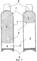
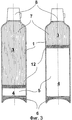
На фиг.1 изображен баллон высокого давления согласно настоящему изобретению с подвижным поршнем в двух различных состояниях наполненности.1 shows a high-pressure cylinder according to the present invention with a movable piston in two different filling states.
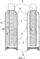
На фиг.2, 3 изображены два других баллона высокого давления согласно настоящему изобретению с внутренним мешком в двух различных состояниях наполненности для каждого из двух баллонов.Figure 2, 3 shows two other high-pressure cylinders according to the present invention with an inner bag in two different filling states for each of the two cylinders.
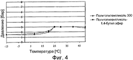
На фиг.4, 5, 6 изображена зависимость давления от температуры в баллонах высокого давления согласно настоящему изобретению, при условии трех различных значений начального давления при температуре 25°С.Figure 4, 5, 6 shows the dependence of pressure on temperature in high-pressure cylinders according to the present invention, provided three different values of the initial pressure at a temperature of 25 ° C.
На фиг.7, 8 изображена зависимость давления в камере для газа-вытеснителя от распыленного объема распыляемого вещества в баллонах высокого давления согласно настоящему изобретению.7, 8 show the dependence of the pressure in the propellant chamber on the atomized volume of the atomized substance in high-pressure cylinders according to the present invention.
Осуществление изобретенияThe implementation of the invention
Баллоны высокого давления согласно настоящему изобретению содержат газ-вытеснитель с жидкой фазой, которая содержит полиэтиленгликоль и/или (C1-C4) моноэфир и/или (C1-C4) диэфир полиэтиленгликоля. Полиэтиленгликоли или их эфиры могут быть чистым веществом. Однако, исходя из особенностей производства, полиэтиленгликоли или их эфиры, как правило, являются смесью различных соединений с разными, например нормально распределенными, молекулярными весами.The high pressure cylinders of the present invention comprise a liquid phase propellant that contains polyethylene glycol and / or (C 1 -C 4 ) monoester and / or (C 1 -C 4 ) polyethylene glycol diester. Polyethylene glycols or their esters can be a pure substance. However, based on the characteristics of production, polyethylene glycols or their esters, as a rule, are a mixture of various compounds with different, for example, normally distributed, molecular weights.
В контексте настоящей заявки молекулярные веса смесей полиэтиленгликолей или их эфиров понимаются как их средневзвешенные молекулярные веса Mw:In the context of this application, the molecular weights of mixtures of polyethylene glycols or their esters are understood as their weighted average molecular weights M w :

где i - индекс для всех видов молекул полиэтиленгликоля и/или моноэфира полиэтиленгликоля и/или диэфира полиэтиленгликоля; и Ni и Mi соответственно - число молекул в i-й молекулярной группе и молекулярный вес i-й молекулярной группы. Как принято в данной области техники, это усредненное значение молекулярного веса Mw может быть определено через измерение рассеивания света по принципу «Multi Angle Light Scattering» (MALS) с использованием света лазера в слабых растворах полиэтиленгликоля или эфира полиэтиленгликоля. Необходимые для этого измерительные устройства известны и представлены на рынке. Mw может быть определен путем расчетов с использованием результатов измерения рассеивания света по уравнению Зимма и связанной с уравнением диаграмме Зимма.where i is the index for all types of polyethylene glycol molecules and / or polyethylene glycol monoester and / or polyethylene glycol diester; and N i and M i, respectively, are the number of molecules in the i-th molecular group and the molecular weight of the i-th molecular group. As is customary in the art, this averaged molecular weight M w can be determined by measuring light scattering according to the Multi Angle Light Scattering (MALS) principle using laser light in weak solutions of polyethylene glycol or polyethylene glycol ether. The necessary measuring devices for this are known and marketed. M w can be determined by calculations using light scattering measurements according to the Zimm equation and the Zimm diagram associated with the equation.
Mw полиэтиленгликоля и/или его эфира может быть выбран как функция от температур внешней среды, при которых предполагается использовать баллон высокого давления согласно данному изобретению. При высоких температурах внешней среды могут быть использованы полиэтиленгликоль с большим молекулярным весом и/или эфир полиэтиленгликоля с большим молекулярным весом, в соответствии с чем полиэтиленгликоль должен быть жидким при желаемой температуре внешней среды. В приведенной ниже таблице представлены обычные диапазоны температур плавления некоторых примерных полиэтиленгликолей, которые могут использоваться согласно настоящему изобретению в зависимости от их молекулярной массы:M w of polyethylene glycol and / or its ester can be selected as a function of ambient temperatures at which it is intended to use a high pressure cylinder according to this invention. At high ambient temperatures, high molecular weight polyethylene glycol and / or high molecular weight polyethylene glycol ether can be used, whereby the polyethylene glycol must be liquid at the desired ambient temperature. The table below shows the usual melting temperature ranges of some exemplary polyethylene glycols that can be used according to the present invention depending on their molecular weight:
Если температура окружающей среды, при которой предполагается использование баллона высокого давления согласно настоящему изобретению, находится в диапазоне, близком к комнатной температуре, то есть в диапазоне от около 0°С до около 40°С, Mw полиэтиленгликоля и/или моноэфира полиэтиленгликоля, и/или диэфира полиэтиленгликоля его эфира предпочтительно равен 200-600 Дальтонам более предпочтительно - 250-390 Дальтонам, и в особенно предпочтительном варианте - приблизительно 300 Дальтонам.If the ambient temperature at which it is intended to use a high-pressure cylinder according to the present invention is in the range close to room temperature, i.e. in the range from about 0 ° C to about 40 ° C, M w of polyethylene glycol and / or mono-ester of polyethylene glycol, and / or diester of its polyethylene glycol ether is preferably 200-600 Daltons, more preferably 250-390 Daltons, and in a particularly preferred embodiment, approximately 300 Daltons.
Примеры моноэфиров полиэтиленгликоля и диэфиров полиэтиленгликоля представлены в Таблице 1 указанной выше публикации в «Canadian Journal of Chemical Engineering». Предпочтительным является использование диэфиров.Examples of polyethylene glycol monoesters and polyethylene glycol diesters are presented in Table 1 of the above publication in the Canadian Journal of Chemical Engineering. The use of diesters is preferred.
Жидкая фаза газа-вытеснителя может при необходимости содержать дополнительный растворитель. Таким дополнительным растворителем могут быть, например, антифризные добавки, такие как дипропиленгликоль или этиленгликоль; а также добавки, модифицирующие вязкость, такие как вода; а также пеноингибиторы, такие как N-октанол. Эти дополнительные растворители в случае, если необходимо их наличие, предпочтительно добавляют в количестве от 0,1 весовых процентов до 5 весовых процентов по отношению к жидкой фазе без диоксида углерода.The liquid phase of the propellant may optionally contain an additional solvent. Such an additional solvent may be, for example, antifreeze additives such as dipropylene glycol or ethylene glycol; as well as viscosity modifying additives, such as water; as well as foaming inhibitors such as N-octanol. These additional solvents, if necessary, are preferably added in an amount of from 0.1 weight percent to 5 weight percent with respect to the liquid phase without carbon dioxide.
В первом предпочтительном варианте выполнения изобретения жидкая фаза содержит только полиэтиленгликоль с Mw в указанных выше диапазонах, при необходимости в комбинации с одним из вышеуказанных дополнительных растворителей.In a first preferred embodiment of the invention, the liquid phase contains only polyethylene glycol with M w in the above ranges, optionally in combination with one of the above additional solvents.
В другом предпочтительном варианте выполнения изобретения жидкая фаза содержит только диэфир полиэтиленгликоля с Mw в указанных выше диапазонах, при необходимости в комбинации с одним из вышеуказанных дополнительных растворителей. Диэфир полиэтиленгликоля в особенно предпочтительном варианте является 1,4-дибутил эфиром, например, «Polyglycol ВВ 300» компании Clariant.In another preferred embodiment, the liquid phase contains only a polyethylene glycol diester with M w in the above ranges, optionally in combination with one of the above additional solvents. A polyethylene glycol diester is particularly preferably 1,4-dibutyl ether, for example, Clariant's "Polyglycol BB 300".
В жидкой фазе газа-вытеснителя общее содержание полиэтиленгликоля и моноэфиров и диэфиров полиэтиленгликоля, и диоксида углерода, растворенного в них, предпочтительно равно, по меньшей мере, 90 весовых процентов жидкой фазы, в более предпочтительном варианте выполнения - по меньшей мере, 95 весовых процентов.In the liquid phase of the propellant, the total content of polyethylene glycol and monoesters and diesters of polyethylene glycol and carbon dioxide dissolved in them is preferably equal to at least 90 weight percent of the liquid phase, in a more preferred embodiment, at least 95 weight percent.
В газовой фазе газа-вытеснителя согласно настоящему изобретению отношение парциального давления диоксида углерода к общему давлению предпочтительно составляет, по меньшей мере, 0.90; в более предпочтительном варианте выполнения - по меньшей мере, 0.95 и в особенно предпочтительном варианте выполнения - по меньшей мере, 0.98.In the gas phase of the propellant according to the present invention, the ratio of the partial pressure of carbon dioxide to the total pressure is preferably at least 0.90; in a more preferred embodiment, at least 0.95; and in a particularly preferred embodiment, at least 0.98.
В предпочтительном варианте выполнения изобретения газ-вытеснитель производится заранее перед тем, как его помещают в баллон высокого давления согласно настоящему изобретению. В реакторе под давлением с манометром в жидкую фазу, содержащую сложное вещество, относящееся к полиэтиленгликолям, и их (С1-С4) моноэфиры и (С1-С4) диэфиры, может быть добавлен диоксид углерода (если необходимо, то перед добавлением диоксида углерода в реакторе под давлением возможно использование вакуума для удаления остатков воздуха). Предпочтительно посредством размешивания или встряхивания газ-вытеснитель уравновешивают, что возможно проверить путем установления постоянного давления.In a preferred embodiment of the invention, the propellant is produced in advance before it is placed in the high pressure cylinder according to the present invention. In a pressure reactor with a manometer, a liquid phase containing a complex substance related to polyethylene glycols and their (C 1 -C 4 ) monoesters and (C 1 -C 4 ) diesters can be added carbon dioxide (if necessary, before adding carbon dioxide in a reactor under pressure, you can use a vacuum to remove residual air). Preferably, by stirring or shaking, the propellant is balanced, which can be verified by establishing a constant pressure.
Начальное давление в баллоне высокого давления согласно настоящему изобретению не зависит от соотношения жидкой фазы и газовой фазы; газ-вытеснитель введен в камеру для газа-вытеснителя; начальное давление в упомянутой камере равно давлению, при котором в нее вводят газ-вытеснитель. Однако снижение давления в камере для газа-вытеснителя при увеличении распыленного объема ΔV зависит от начального объема жидкой фазы и всего объема газа-вытеснителя (то есть от начального объема камеры для газа-вытеснителя), от числа молей всех компонентов газа-вытеснителя (упомянутые компоненты также определяют отношение жидкой фазы к газовой фазе) и от температуры:The initial pressure in the high-pressure tank according to the present invention does not depend on the ratio of the liquid phase and the gas phase; propellant is introduced into the propellant chamber; the initial pressure in said chamber is equal to the pressure at which a propellant is introduced into it. However, the decrease in pressure in the chamber for the propellant with increasing atomized volume ΔV depends on the initial volume of the liquid phase and the total volume of the propellant (i.e., the initial volume of the chamber for the propellant), on the number of moles of all components of the propellant (the mentioned components also determine the ratio of the liquid phase to the gas phase) and the temperature:
![]()
![]()
гдеWhere
- VT0 - начальный объем всего газа-вытеснителя, т.е. начальный объем камеры для газа-вытеснителя;- V T0 is the initial volume of the total propellant, i.e. the initial volume of the chamber for the propellant;
- Ng - суммарное количество молей диоксида углерода в жидкой фазе и газовой фазе газа-вытеснителя (остается постоянным, так как диоксид углерода не распыляется из баллонов высокого давления согласно настоящему изобретению);- N g - the total number of moles of carbon dioxide in the liquid phase and the gas phase of the propellant (remains constant, since carbon dioxide is not sprayed from high-pressure cylinders according to the present invention);
- Nl - суммарное количество молей всех жидких компонентов (полиэтиленгликоля, моноэфира полиэтиленгликоля, диэфира полиэтиленгликоля и дополнительных растворителей) жидкой фазы газа-вытеснителя (остается постоянным, так как жидкая фаза не распыляется из баллона высокого давления согласно настоящему изобретению); и- N l is the total number of moles of all liquid components (polyethylene glycol, polyethylene glycol monoester, polyethylene glycol diester and additional solvents) of the propellant liquid phase (remains constant, since the liquid phase is not sprayed from the high-pressure cylinder according to the present invention); and
- Т - абсолютная температура.- T is the absolute temperature.
Используя простое измерительное оборудование, можно экспериментально определить зависимость (1а) для каждого баллона высокого давления согласно настоящему изобретению и для каждого газа-вытеснителя (см. ниже описание фигур 7 и 8).Using simple measuring equipment, it is possible to experimentally determine the dependence (1a) for each high-pressure cylinder according to the present invention and for each propellant (see the description of figures 7 and 8 below).
Если предполагается, что газ в составе газа-вытеснителя является чистым диоксидом углерода, а жидкие компоненты газа-вытеснителя являются нелетучими, то возможно рассчитать обратную зависимость (1b):If it is assumed that the gas in the propellant is pure carbon dioxide, and the liquid components of the propellant are non-volatile, then it is possible to calculate the inverse relationship (1b):
![]()
![]()
из которой в свою очередь может быть получена зависимость (1а). Для этого необходимы для начала несколько формул, описанных ниже:from which, in turn, dependence (1a) can be obtained. To do this, you need to start with several formulas described below:
а) При давлениях и температурах, возникающих обычно в баллонах высокого давления согласно настоящему изобретению, равновесное распределение диоксида углерода между газовой фазой и жидкой фазой может быть определено по следующей формуле:a) At pressures and temperatures that usually occur in high-pressure cylinders according to the present invention, the equilibrium distribution of carbon dioxide between the gas phase and the liquid phase can be determined by the following formula:
![]()
![]()
где Where
- ![]()
![]()
- ![]()
![]()
- H и Н0 характерные константы для жидкой фазы и температуры.- H and H 0 are characteristic constants for the liquid phase and temperature.
Константы Н и Н0 могут быть определены способом, описанным в вышеуказанном источнике «ACS Symposium Series» (стр.168, разделы «Batch Unit» и «Solubility Studies»). В упомянутой публикации полиэтиленгликоль с молекулярной массой Mw 400 имел H=9,4 МПа при температуре 25°С (H0 равен приблизительно -0,5 МПа согласно фиг.3 упомянутой публикации). В исследованиях, результатом которых стала настоящая заявка, полиэтиленгликоль с молекулярным весом Mw 300 имел H=32,8 МПа и Н0=-0,39 МПа при температуре 25°С.The constants H and H 0 can be determined by the method described in the above source, “ACS Symposium Series” (p. 168, sections “Batch Unit” and “Solubility Studies”). In the aforementioned publication, polyethylene glycol with a molecular weight of M w 400 had H = 9.4 MPa at a temperature of 25 ° C (H 0 is approximately −0.5 MPa according to FIG. 3 of said publication). In the studies that led to the present application, polyethylene glycol with a molecular weight of M w 300 had H = 32.8 MPa and H 0 = -0.39 MPa at a temperature of 25 ° C.
б) Мольная доля ![]()
![]()

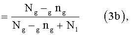
гдеWhere
- lng - число молей диоксида углерода в жидкой фазе газа-вытеснителя;- l n g is the number of moles of carbon dioxide in the liquid phase of the propellant;
- gng - число молей диоксида углерода в газовой фазе газа-вытеснителя и- g n g is the number of moles of carbon dioxide in the gas phase of the propellant and
- Ng и Nl см. выше.- N g and N l see above.
в) Если (2) и (3b) объединить и решить используя значение gng, получаем:c) If (2) and (3b) are combined and solved using the value of g n g , we obtain:
![]()
![]()
г) Уравнение Ван-дер-Ваальса:d) The equation of van der Waals:

гдеWhere
- Р и gng - см. выше;- P and g n g - see above;
- gV - объем газовой фазы;- g V is the volume of the gas phase;
- R - универсальная газовая константа и- R is the universal gas constant and
- а и b - коэффициенты Ван-дер-Ваальса для диоксида углерода, т.е. 3,96×10⁻¹ Па·м3 и 42,69×10⁻⁶ м3/моль.- a and b are the van der Waals coefficients for carbon dioxide, i.e. 3.96 × 10 -1 Pa · m 3 and 42.69 × 10 -6 m 3 / mol.
д) Объем lV жидкой фазы газа-вытеснителя примерно определяется как:d) Volume l V of the liquid phase of the propellant is approximately determined as:
![]()
![]()
![]()
![]()
гдеWhere
- lV0 - объем жидкой фазы газа-вытеснителя без диоксида углерода (это значение постоянно) и- l V 0 is the volume of the liquid phase of the propellant without carbon dioxide (this value is constant) and
- Ng, gng, lng и b - см. выше.- N g , g n g , l n g and b - see above.
В формулах (6а) и (6b) предполагается, что жидкая фаза несжимаема, то есть изменение объема жидкой фазы происходит только путем поглощения или выпуска углекислого газа. Дополнительно предполагается, что не происходит никаких взаимодействий между растворенным диоксидом углерода и молекулами жидкой фазы, взаимодействия между которыми могли бы привести к дополнительному изменению объема.In formulas (6a) and (6b), it is assumed that the liquid phase is incompressible, that is, the change in the volume of the liquid phase occurs only by absorption or release of carbon dioxide. Additionally, it is assumed that there are no interactions between dissolved carbon dioxide and liquid phase molecules, the interactions between which could lead to an additional change in volume.
е) Общий распыленный объем ΔV, используемый в формулах (1а) и (1b), равен:e) The total atomized volume ΔV used in formulas (1a) and (1b) is equal to:
![]()
![]()
где lV, gV и VT0 имеют указанное выше значение.where l V, g V and V T0 have the above meaning.
ё) Общее количество молей Nl в жидкой фазе (без диоксида углерода; константа), используемое в формулах (1a), (1b), (3а), (3b) и (4), может быть рассчитано по следующей формуле (8):g) The total number of moles N l in the liquid phase (without carbon dioxide; constant) used in formulas (1a), (1b), (3a), (3b) and (4) can be calculated using the following formula (8) :

гдеWhere
- m(PEG), m(PEGMonoether) и m(PEGDiether) являются произвольно выбираемыми массами полиэтиленгликоля или моноэфира полиэтиленгликоля или диэфира полиэтиленгликоля;- m (PEG), m (PEGMonoether) and m (PEGDiether) are randomly selected masses of polyethylene glycol or polyethylene glycol monoester or polyethylene glycol diester;
- Mw(PEG), Mw(PEGMonoether) и Mw(PEGDiether) представляют собой средневзвешенные молекулярные веса полиэтиленгликоля или моноэфира полиэтиленгликоля или диэфира полиэтиленгликоля (которые могут быть определены способом, описанным выше); и- M w (PEG), M w (PEGMonoether) and M w (PEGDiether) are weighted average molecular weights of polyethylene glycol or polyethylene glycol monoester or polyethylene glycol diester (which can be determined by the method described above); and
- nl - число молей возможных дополнительных растворителей,- n l is the number of moles of possible additional solvents,
ж) общее количество молей Ng диоксида углерода жидкой фазы и газовой фазы газа-вытеснителя (постоянно), используемое в формулах (1a), (1b), (3b), (4) и (6b), может быть рассчитано по следующей формуле (9):g) the total number of moles N g of carbon dioxide in the liquid phase and gas phase of the propellant (constant) used in formulas (1a), (1b), (3b), (4) and (6b) can be calculated using the following formula (9):

гдеWhere
- r - единственное вещественное и положительное решение кубического уравнения ![]()
![]()
- VT0, 1V0, а, b, Н и Н0 - см. выше.- V T0 , 1 V 0 , a, b, H and H 0 - see above.
Для построения кривой по формуле (1b) сначала определяют Nl и Ng по формулам (8) и (9) соответственно. Для определения взаимозависящих значений Р и ΔV данной кривой совершают следующие действия:To construct a curve according to formula (1b), N l and N g are first determined by formulas (8) and (9), respectively. To determine the interdependent values of P and ΔV of this curve, the following actions are performed:
а) Давление Р выбирается из значений, лежащих в обычном диапазоне значений для баллона высокого давления согласно настоящему изобретению; это давление не должно быть больше, чем начальное давление Р0, взятое для формулы (9);a) Pressure P is selected from values lying in the usual range of values for the high-pressure cylinder according to the present invention; this pressure should not be greater than the initial pressure P 0 taken for formula (9);
б) с таким Р для вычисления gng используется формула (4);b) with such P, formula (4) is used to calculate g n g ;
в) с известными Р и gng для определения gV используется формулаC) with known P and g n g to determine g V the formula is used
(5), преобразуемая в кубическое уравнение с gV, причем gV определяют как единственное вещественное и положительное решение этого уравнения;(5) transformable into a cubic equation with g V, moreover, g V is defined as the only real and positive solution to this equation;
г) с известным gng для определения 1V используется формула (6b);d) with known g n g, for the determination of 1 V, formula (6b) is used;
д) с известными gV и lV для определения взаимозависящих ΔV и Р используется формула (7).d) with the known g V and l V to determine the interdependent ΔV and P, the formula (7) is used.
Полученные таким образом взаимозависящие значения Р и ΔV могут быть нанесены на плоскость координат как Р (ось y) и ΔV (ось х), что позволит построить кривую по формуле (1b); а также как ΔV (ось y) и Р (ось x), что позволит построить график по формуле (1а).The interdependent P and ΔV values thus obtained can be plotted on the coordinate plane as P (y axis) and ΔV (x axis), which will allow us to construct the curve according to formula (1b); as well as ΔV (y axis) and P (x axis), which allows you to build a graph according to formula (1a).
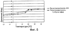
Зависимость давления в камере для газа-вытеснителя баллона высокого давления согласно настоящему изобретению от температуры неожиданно сравнительно низка. Это обусловлено тем, что давление, возрастающее с повышением температуры в газовой фазе, частично компенсируется поглощением диоксида углерода, подобным же образом повышающимся в жидкой фазе, что приводит к снижению количества диоксида углерода в газовой фазе. Это проиллюстрировано на фигурах 4-6 на примере полиэтиленгликоля 300 (фигуры 4 и 5) и дибутил эфира полиэтиленгликоля (фигура 6). При температуре ~25°С давление меняется на ~ 2 бар. До и после этого скачка температуры давление как функция температуры сравнительно неизменно. Скачок давления при температуре ~25°С происходит вне зависимости от количества растворенного диоксида углерода и, соответственно, вне зависимости от абсолютной величины давления при температуре ~25°С.The temperature dependence of the pressure in the chamber for the propellant of the high-pressure cylinder according to the present invention is unexpectedly relatively low. This is because the pressure increasing with increasing temperature in the gas phase is partially compensated by the absorption of carbon dioxide, similarly increasing in the liquid phase, which leads to a decrease in the amount of carbon dioxide in the gas phase. This is illustrated in figures 4-6 on the example of polyethylene glycol 300 (figures 4 and 5) and dibutyl ether of polyethylene glycol (figure 6). At a temperature of ~ 25 ° C, the pressure changes by ~ 2 bar. Before and after this jump in temperature, pressure as a function of temperature is relatively constant. The pressure jump at a temperature of ~ 25 ° C occurs regardless of the amount of dissolved carbon dioxide and, accordingly, regardless of the absolute value of pressure at a temperature of ~ 25 ° C.
Баллоны высокого давления согласно настоящему изобретению имеют разделяющую часть, выполненную с возможностью подвижного разделения внутреннего пространства на камеру для газа-вытеснителя и на камеру для хранения. Данная разделяющая часть может иметь форму любого из средств, используемых в известных баллонах высокого давления с разделенным внутренним пространством, например, в баллонах высокого давления типа «мешок в баллоне» или «баллон в баллоне», указанных во введении, или баллонах высокого давления с подвижным поршнем. То, из каких материалов изготовлена упомянутая разделяющая часть, не является принципиальным, если эти материалы не растворяются под действием соответствующего полиэтиленгликоля и/или моноэфира или диэфира полиэтиленгликоля. Примерами материалов, подходящих для мембраноподобных разделяющих частей, являются гибкие пластмассы, которым придают нерастворимые свойства путем структурирования, такие как вулканизированные резины или латекс; или структурированные полиэстеры или полиэфиры полиэстера. Применимы также и ламинированные пленки или пленки из металлов без примесей, например, сделанные из алюминия. Из-за использования жидкой фазы газа-вытеснителя разделяющая часть должна быть выполнена с возможностью непроницаемого для жидкостей разделения между камерой для хранения и камерой для газа-вытеснителя. Предпочтительно, чтобы разделяющая часть также формировала газонепроницаемый барьер между камерой для хранения и камерой для газа-вытеснителя. В баллонах высокого давления согласно настоящему изобретению разделяющая часть предпочтительно выполнена в виде подвижного клапана или растяжимого и/или сжимающегося внутреннего мешка.The high-pressure cylinders according to the present invention have a separating part configured to movably separate the interior space into a propellant chamber and into a storage chamber. This separating part may take the form of any of the means used in known high-pressure cylinders with a divided interior, for example, high-pressure cylinders such as "bag in a cylinder" or "cylinder in a cylinder", indicated in the introduction, or high-pressure cylinders with a movable the piston. What materials the said separating part is made of is not critical if these materials are not dissolved by the action of the corresponding polyethylene glycol and / or monoester or polyethylene glycol diester. Examples of materials suitable for membrane-like separating parts are flexible plastics that provide insoluble properties by crosslinking, such as vulcanized rubbers or latex; or structured polyesters or polyesters. Also applicable are laminated films or films of metals without impurities, for example, made of aluminum. Due to the use of the liquid phase of the propellant, the separating part must be adapted for liquid-tight separation between the storage chamber and the propellant chamber. Preferably, the separating portion also forms a gas-tight barrier between the storage chamber and the propellant chamber. In the high-pressure cylinders of the present invention, the separation part is preferably made in the form of a movable valve or an expandable and / or compressible inner bag.
Баллон высокого давления согласно настоящему изобретению также может иметь клапан и распылительную головку, так что вещество можно контролируемо распылять в окружающую среду путем приведения в действие распылительной головки и клапана. Баллон высокого давления согласно настоящему изобретению является в этом случае предпочтительно аэрозольным контейнером или банкой с аэрозолем. В альтернативном варианте выполнения это может быть также картридж, у которого нет выпускного клапана и в котором прокалывают отверстие в стенке контейнера, только когда его помещают в устройство для выпуска, причем это отверстие в то же самое время должно закрываться выпускным клапаном.The high pressure cylinder according to the present invention may also have a valve and a spray head, so that the substance can be sprayed in a controlled manner into the environment by actuating the spray head and valve. The high pressure cylinder according to the present invention is in this case preferably an aerosol container or an aerosol can. In an alternative embodiment, it can also be a cartridge that does not have an outlet valve and in which a hole in the container wall is pierced only when it is placed in the outlet device, and this hole must be closed by the outlet valve at the same time.
Выражение "по меньшей мере часть длины центральной оси", использованное в формуле изобретения, означает предпочтительно по меньшей мере 50 процентов общей длины центральной оси внутреннего пространства. В случае если внутреннее пространство неосесимметрично, термин «центральная ось» означает наиболее длинную из возможных прямых линий, которая может быть проведена в пределах внутреннего пространства и которая определяется двумя геометрическими точками проникновения этой линии через внутреннюю поверхность стенки внутреннего пространства. В случае если внутреннее пространство осесимметрично, центральная ось является осью вращения. Общая длина центральной оси во всех случаях определяется двумя геометрическими точками проникновения центральной оси через внутреннюю поверхность стенки внутреннего пространства. Выражение «по меньшей мере часть внутреннего пространства», использованное в формуле изобретения, предпочтительно означает по меньшей мере 70 процентов общего объема внутреннего пространства.The expression “at least a portion of the length of the central axis” used in the claims preferably means at least 50 percent of the total length of the central axis of the interior. If the inner space is axisymmetric, the term “central axis” means the longest possible straight line that can be drawn within the inner space and which is determined by two geometric points of penetration of this line through the inner surface of the wall of the inner space. In case the internal space is axisymmetric, the central axis is the axis of rotation. The total length of the central axis in all cases is determined by two geometric points of penetration of the central axis through the inner surface of the wall of the inner space. The expression “at least part of the interior” as used in the claims preferably means at least 70 percent of the total volume of the interior.
Во всех вариантах выполнения баллона высокого давления согласно настоящему изобретению внутреннее пространство предпочтительно имеет вдоль, по меньшей мере, части длины этой центральной оси осесимметричную форму, в частности цилиндрическую..In all embodiments of the high pressure cylinder according to the present invention, the interior preferably has an axisymmetric shape, at least partly cylindrical, along at least a portion of the length of this central axis.
Вещество, которое может быть введено в баллоны высокого давления согласно настоящему изобретению, является веществом, которое имеет газообразную или жидкую форму при температуре, при которой используется баллон высокого давления, или сухим высокодисперсным веществом, или высокодисперсным веществом, находящимся во взвешенном состоянии в жидкости, как и в известных баллонах высокого давления, а особенно в известных аэрозольных контейнерах. В контексте настоящей заявки термин «высокодисперсный» означает, что высокодисперсное вещество может быть распылено посредством обычной распылительной насадки. Предпочтительно термин «высокодисперсный» обозначает, что частица имеет размер в диапазоне от приблизительно 0.1 мкм до приблизительно 100 мкм в диаметре (определяемый как «средний массовый аэродинамический диаметр», СМАД). В особенно предпочтительном варианте выполнения термин «высокодисперсный» означает размер частицы в диапазоне от приблизительно 1 мкм до приблизительно 6 мкм.A substance that can be introduced into high-pressure cylinders according to the present invention is a substance that has a gaseous or liquid form at a temperature at which a high-pressure cylinder is used, or a dry, highly dispersed substance, or a highly dispersed substance in suspension in a liquid, as and in known high pressure cylinders, and especially in known aerosol containers. In the context of the present application, the term “finely divided” means that the finely divided substance can be sprayed using a conventional spray nozzle. Preferably, the term "finely divided" means that the particle has a size in the range from about 0.1 μm to about 100 μm in diameter (defined as "average mass aerodynamic diameter", ABPM). In a particularly preferred embodiment, the term “finely divided” means a particle size in the range of from about 1 μm to about 6 μm.
Баллоны высокого давления согласно настоящему изобретению могут быть произведены и наполнены аналогично известным баллонам высокого давления. В частности, варианты выполнения настоящего изобретения с использованием клапанов и головок для распыления, которые используются в баллонах высокого давления согласно настоящему изобретению, могут быть аналогичными тем, которые используются в известных баллонах, например, в баллонах типа «мешок в баллоне», упомянутом во введении.The high-pressure cylinders of the present invention can be produced and filled similarly to known high-pressure cylinders. In particular, embodiments of the present invention using valves and spray heads used in high pressure cylinders of the present invention may be similar to those used in known cylinders, for example, bag-in-bottle cylinders mentioned in the introduction .
Обычно создание баллона высокого давления начинается с создания сформованной контейнерной заготовки из подходящего материала. Заготовка может быть изготовлена из выдерживающего давление термопластического материала, например из акрилонитрил/бутадиен/стирол сополимера, поликарбоната или полиэстера, такого как полиэтилентерефталат, или предпочтительно из листового металла, такого как листовая нержавеющая сталь или листовой алюминий. Заготовка предпочтительно имеет цилиндрическую форму, которая создается путем сужения и закругления ее верхнего конца. Эта заготовка может быть изготовлена способом, который сам по себе известен, путем литья под давлением (для пластмассовых контейнеров) или холодного или горячего прессования (для металлических контейнеров).Typically, the creation of a high pressure cylinder begins with the creation of a molded container blank of a suitable material. The preform may be made of a pressure-resistant thermoplastic material, for example, acrylonitrile / butadiene / styrene copolymer, polycarbonate or polyester, such as polyethylene terephthalate, or preferably sheet metal, such as stainless steel sheet or aluminum sheet. The preform preferably has a cylindrical shape, which is created by narrowing and rounding its upper end. This preform can be made in a manner that is known per se by injection molding (for plastic containers) or cold or hot pressing (for metal containers).
Ниже приведены некоторые примеры применения способов заполнения баллона:The following are some examples of application methods for filling a cylinder:
1) В баллоне высокого давления, в котором разделение камеры для хранения и камеры для газа-вытеснителя осуществляется посредством поршня, мембрана или мешок могут быть наполнены способом, согласно которому используется контейнерная заготовка с открытым верхним концом, и предпочтительно имеющая выгнутую внутрь поверхность основания с закрывающимся отверстием (этот способ аналогичен способу, описанному в ЕР-А-0 017 147). Упомянутый поршень вставляют в контейнерную заготовку на желаемую глубину через открытый верхний конец, причем от упомянутой глубины в значительной мере зависит соотношение объема камеры для хранения (над поршнем) и объема камеры для газа-вытеснителя (под поршнем). В настоящем варианте выполнения контейнерной заготовке, если требуется, придают суженную округлую форму только после вставки поршня. Вещество вводят сверху таким образом, что оно растекается по поршню, и верхнее отверстие закрывают пластиной, которая, если требуется, может иметь выпускной клапан, причем эту пластину обжимают вокруг краев отверстия. На заключительном этапе через отверстие в основании заготовки вводят газ-вытеснитель до достижения желаемого давления и закрывают отверстие подходящей пробкой.1) In a high-pressure tank in which the storage chamber and the propellant chamber are separated by a piston, the membrane or bag can be filled in a manner according to which a container blank with an open upper end is used, and preferably having an inwardly curved base surface with a closable hole (this method is similar to the method described in EP-A-0 017 147). The said piston is inserted into the container blank to the desired depth through the open upper end, and the ratio of the volume of the storage chamber (above the piston) and the volume of the chamber for the propellant (under the piston) largely depends on the said depth. In the present embodiment, the container blank, if required, is given a narrowed rounded shape only after insertion of the piston. The substance is introduced from above in such a way that it spreads along the piston, and the upper hole is closed with a plate, which, if required, can have an exhaust valve, and this plate is pressed around the edges of the hole. At the final stage, a propellant is introduced through the hole in the base of the preform until the desired pressure is reached and the hole is closed with a suitable stopper.
2) Баллон высокого давления, разделенный внутренним мешком или мембраной, может быть наполнен следующим образом: внутренний мешок или мембрану вставляют в контейнерную заготовку через верхнее отверстие способом, описанным в пункте 1) (хотя в этом случае верхней части заготовки может быть уже придана суженная форма) и плотно закрепляют вокруг края отверстия. В заготовке внутренний мешок развертывают путем заполнения или растягивают мембрану, и таким образом в верхней части заготовки формируется камера для хранения, заполненная веществом. Затем отверстие, на краях которого плотно закреплена часть мешка или мембраны, герметично закрывают пластиной, которая факультативно может иметь клапан и которую обжимают вокруг отверстия. В заключение через отверстие в основании заготовки вводят газ-вытеснитель до достижения желаемого давления и закрывают отверстие подходящей пробкой.2) The high-pressure cylinder, separated by an inner bag or membrane, can be filled as follows: the inner bag or membrane is inserted into the container blank through the upper hole in the manner described in paragraph 1) (although in this case the narrowed shape may already be given to the upper part of the blank ) and tightly fasten around the edge of the hole. In the preform, the inner bag is deployed by filling or stretching the membrane, and thus a storage chamber filled with a substance is formed in the upper part of the preform. Then the hole, at the edges of which a part of the bag or membrane is tightly fixed, is hermetically sealed with a plate, which optionally can have a valve and which is crimped around the hole. In conclusion, a propellant is introduced through the hole in the base of the preform until the desired pressure is reached and the hole is closed with a suitable stopper.
3) Баллон высокого давления с внутренним мешком в качестве разделяющей части и клапаном может быть создан из контейнерной заготовки без отверстия в основании. На первом этапе в контейнерную заготовку через верхнее отверстие вводят заранее определенное количество газа-вытеснителя. Затем края пластины, имеющей клапан, и к которой уже герметично прикреплены внутренний мешок или мембрана, загибают или фланцируют на краях заготовки, заранее заполненной газом-вытеснителем. Внутренний мешок или мембрана в этом случае все еще остаются незаполненными распыляемым веществом. В этом случае пластина предпочтительно имеет полую напорную трубку, присоединенную к клапану и имеющую отверстия, на которую в начале кладут или накручивают внутренний мешок или мембрану. Эта напорная трубка проникает во внутреннее пространство контейнерной заготовки во время загибания или фланцирования крышки. После того как загнули или фланцировали пластину, во внутренний мешок или мембрану вводят вещество посредством использования стержня клапана под давлением выше, чем внутреннее давление газа-вытеснителя в контейнерной заготовке. При использовании упомянутой трубки через стержень клапана в нее поступает вещество и наполняет внутренний мешок через имеющиеся в этой трубке отверстия.3) A high-pressure cylinder with an inner bag as a separating part and a valve can be created from a container blank without a hole in the base. At the first stage, a predetermined amount of propellant is introduced into the container billet through the upper opening. Then the edges of the plate having a valve, and to which the inner bag or membrane is already hermetically attached, are bent or flanged at the edges of the workpiece pre-filled with propellant. The inner bag or membrane in this case still remains empty with the sprayed substance. In this case, the plate preferably has a hollow pressure tube attached to the valve and having openings on which an inner bag or membrane is laid or wound at the beginning. This pressure tube penetrates into the interior of the container blank during bending or flanking of the lid. After the plate has been bent or flanged, a substance is introduced into the inner bag or membrane by using a valve stem under a pressure higher than the internal pressure of the propellant in the container blank. When using the above-mentioned tube through the valve stem, substance enters into it and fills the inner bag through the openings in the tube.
4) Баллон высокого давления с внутренним мешком или мешком типа «баллон в баллоне» с клапаном может быть заполнен следующим образом: внутренний мешок или внутренний контейнер, который может быть все еще пуст или уже наполнен, вначале вставляют во внутреннюю часть контейнерной заготовки. Клапан крепят клапанной пластиной на край контейнерной заготовки, но неплотно и в любом случае негерметично, или располагают на очень небольшом расстоянии над краем контейнерной заготовки. Устройство для наполнения по принципу «колокола» вставляют сверху в контейнерную заготовку над неплотно закрепленной клапанной пластиной, причем упомянутое устройство крепится к внешней стенке контейнерной заготовки герметично, что достигается посредством использования подходящего уплотнителя. Так как плоская сторона клапана некрепко закреплена на крае контейнерной заготовки, сжатый газ-вытеснитель может быть затем введен при помощи устройства для наполнения во внутреннее пространство контейнерной заготовки через пропускающую жидкости щель между клапанной пластиной и краем контейнерной заготовки. После того как внутреннее пространство контейнерной заготовки заполнено газом-вытеснителем, клапанная пластина должна быть герметично соединена с краем контейнерной заготовки, что обычно производится при помощи уплотнителя, расположенного в пластине клапана, и путем обжатия краев пластины клапана. После этого, если внутренний мешок или внутренний контейнер еще не был заполнен распыляемым веществом, он может быть заполнен веществом посредством использования стержня клапана.4) A high-pressure cylinder with an inner bag or a bag-in-cylinder bag with a valve can be filled as follows: the inner bag or inner container, which may still be empty or already full, is first inserted into the inside of the container blank. The valve is secured by a valve plate to the edge of the container blank, but is leaking and in any case leaky, or is placed at a very small distance above the edge of the container blank. The filling device according to the “bell” principle is inserted from above into the container blank over a loosely fixed valve plate, said device being attached to the outer wall of the container blank tightly, which is achieved by using a suitable sealant. Since the flat side of the valve is loosely attached to the edge of the container preform, the compressed propellant can then be introduced by means of a device to fill the container preform through the fluid gap between the valve plate and the edge of the container preform. After the interior of the container blank is filled with a propellant, the valve plate must be hermetically connected to the edge of the container blank, which is usually done with a seal located in the valve plate and by crimping the edges of the valve plate. After that, if the inner bag or inner container has not yet been filled with the atomized substance, it can be filled with the substance by using a valve stem.
5) В случае применения контейнера с поршнем в качестве разделяющей части возможно использовать заготовку контейнера цилиндрической формы, закрытую сверху, факультативно уже имеющую клапан, но все еще открытую снизу. В этом случае заранее определенное количество вещества сначала вводят в контейнерную заготовку, перевернутую вверх дном, после чего в заготовку на желаемую глубину вставляют поршень. Затем вводят надлежащее количество газа-вытеснителя и нижний конец контейнерной заготовки фланцируют с днищем контейнера.5) In the case of using a container with a piston as a separating part, it is possible to use a cylindrical-shaped container blank closed at the top, optionally already having a valve, but still open at the bottom. In this case, a predetermined amount of the substance is first introduced into the container blank turned upside down, after which a piston is inserted into the blank to the desired depth. An appropriate amount of propellant is then introduced and the lower end of the container blank is flanged with the bottom of the container.
Некоторые газы-вытеснители, которые могут быть использованы в баллонах высокого давления согласно настоящему изобретению, сами обладают новизной и вследствие этого являются объектами настоящего изобретения. К ним относятся газы-вытеснители, составленные из: а) газовой фазы, содержащей диоксид углерода, и б) жидкой фазы, содержащей более 90 весовых процентов жидкой фазы полиэтиленгликоля и растворенного в ней диоксида углерода, при условии, что это соединение не является полиэтиленгликолем 400.Some propellant gases that can be used in the high-pressure cylinders of the present invention themselves are novel and therefore are objects of the present invention. These include propellants composed of: a) a gas phase containing carbon dioxide, and b) a liquid phase containing more than 90 weight percent of the liquid phase of polyethylene glycol and the carbon dioxide dissolved in it, provided that this compound is not polyethylene glycol 400 .
Приведенные выше комментарии, касающиеся предпочтительных диапазонов молекулярного веса и компонентов полиэтиленгликоля в жидкой фазе, также применимы к газам-вытеснителям согласно настоящему изобретению.The above comments regarding preferred molecular weight ranges and liquid phase polyethylene glycol components are also applicable to propellants according to the present invention.
Ниже приводится описание конкретных вариантов выполнения баллона высокого давления согласно настоящему изобретению со ссылкой на фигуры.The following is a description of specific embodiments of the high pressure cylinder according to the present invention with reference to the figures.
На фиг.1 изображен цилиндрический аэрозольный баллон с наружной стенкой 1, выполненной из листа алюминия, внутри которого находится внутренний мешок 2, разделяющий внутреннее пространство баллона на камеру 3 для хранения и камеру 4 для газа-вытеснителя. Камера 4 для газа-вытеснителя содержит газ-вытеснитель согласно настоящему изобретению. Он состоит из газовой фазы 5 с полным давлением в газовой фазе, обычно приблизительно равным 5 бар, причем соотношение парциального давления диоксида углерода к полному давлению может составлять 0,98; а также из жидкой фазы 6, которая в основном состоит из полиэтиленгликоля с молекулярным весом (Mw) 300 и растворенного в нем диоксида углерода. Камера 3 для хранения наполнена жидким веществом 7, которое может быть распылено из аэрозольного баллона посредством обычного клапана (не показано на фигуре) и посредством обычной распылительной головки 8. Слева изображен наполненный аэрозольный баллон, справа - почти полностью пустой аэрозольный баллон, причем мембрана 2 вытеснена вверх.Figure 1 shows a cylindrical aerosol can with an
На фиг.2 изображен аэрозольный баллон согласно настоящему изобретению с наружной стенкой 1 из нержавеющей стали. Внутреннее пространство баллона разделено посредством внутреннего мешка 2 на камеру 3 для хранения и камеру 4 для газа-вытеснителя. Камера 3 для хранения наполнена высокодисперсным веществом 9 (например, сухим порошком с размером частиц, подходящим для вдыхания). Камера 4 для газа-вытеснителя содержит газ-вытеснитель, который состоит из газовой фазы 5 и жидкой фазы 6. Газовая фаза обычно имеет полное давление примерно 4 бар, причем соотношение парциального давления диоксида углерода к полному давлению может составлять примерно 0,99. Жидкая фаза состоит в основном из полиэтиленгликоля с молекулярным весом (Мw) 250 и растворенного в нем диоксида углерода. В данном варианте выполнения внутренний мешок 2 содержит внутри себя полую напорную трубку 10 со сквозными отверстиями 11. Посредством сжатия или деформации внутреннего мешка 2 (правая сторона фиг.2) распыляемое вещество под давлением попадает через отверстия 11 в напорную трубку 10 и через напорную трубку 10 к клапану (не показан), расположенному во внутренней части распылительной головки 8.Figure 2 shows an aerosol can according to the present invention with an
На фиг.3 изображен аэрозольный баллон согласно настоящему изобретению с наружной стенкой 1, выполненной из листа нержавеющей стали. Внутреннее пространство аэрозольного баллона поделено на камеру 3 для хранения и камеру 4 для газа-вытеснителя посредством поршня 12, который может быть выполнен, например, из полихлорвинила (PVC). В данном варианте выполнения изобретения аэрозольный баллон на протяжении, по меньшей мере, части длины центральной оси имеет поперечное сечение постоянной формы, предпочтительно цилиндрическое поперечное сечение. На фигуре центральная ось показана пунктирной линией. Поршень 12 подогнан по поперечному сечению внутреннего пространства. Камера 3 для хранения содержит жидкое распыляемое вещество 7. Камера для газа-вытеснителя содержит газ-вытеснитель, который состоит из газовой фазы 5 и жидкой фазы 6. Газовая фаза обычно имеет полное давление примерно 4 бар, причем соотношение парциального давления диоксида углерода к полному давлению составляет примерно 0,95. Жидкая фаза 6 состоит в основном из дибутилэфира полиэтиленгликоля с молекулярным весом примерно 350 и растворенного в нем диоксида углерода. На верхней части аэрозольного баллона установлена распылительная головка 8, которая внутри имеет клапан (не показан на фигуре). Справа на фиг.3 изображено, как объем камеры 3 для хранения уменьшился посредством перемещения поршня 12 вверх.Figure 3 shows an aerosol can according to the present invention with an
На фиг.4-6 изображена зависимость давления в камере для газа-вытеснителя от температуры, когда газовая фаза содержит полиэтиленгликоль с молекулярным весом 300 или дибутилэфир полиэтиленгликоля. Для этих измерений в качестве имитации камеры с газом-вытеснителем были использованы пластифицированные стеклянные сосуды объемом 100 мл. Они были предварительно плотно закрыты и вакуумированы, и в вакуумированные стеклянные сосуды при помощи шприца впрыскивали жидкий газ-вытеснитель, свободный от диоксидуглеродной фазы (примерно 10 г). Желаемое количество СO2 подавали из газового баллона в стеклянные сосуды при встряхивании до тех пор, пока после уравновешивания температуры до 25°С, не достигалось желаемое исходное давление. Было выбрано три различных значения исходного давления (фиг.4: 2,5 бар, фиг.5: около 5 бар, фиг.6: 7 бар). Давление измеряли при различных температурах. Температура -15°С была достигнута в соляном растворе, который был предварительно охлажден в морозильной камере. Температура 8°С была достигнута посредством уравновешивания в холодильной камере. Для уравновешивания с достижением температуры 20°С, 25°С, 30°С, 40°С и 50°С стеклянные сосуды были помещены в водяную баню. Давление, устанавливающееся после уравновешивания температуры, измеряли при помощи ручного манометра.Figure 4-6 shows the temperature dependence of the pressure in the chamber of the propellant, when the gas phase contains polyethylene glycol with a molecular weight of 300 or dibutyl ether of polyethylene glycol. For these measurements, plasticized glass vessels with a volume of 100 ml were used as an imitation of a chamber with a propellant. They were previously tightly closed and evacuated, and a liquid propellant free of the carbon dioxide phase (about 10 g) was injected into the evacuated glass vessels using a syringe. The desired amount of CO 2 was supplied from the gas cylinder into the glass vessels with shaking until, after equilibrating the temperature to 25 ° C, the desired initial pressure was reached. Three different initial pressure values were selected (FIG. 4: 2.5 bar, FIG. 5: about 5 bar, FIG. 6: 7 bar). Pressure was measured at various temperatures. A temperature of -15 ° C was achieved in brine, which was previously cooled in the freezer. A temperature of 8 ° C was achieved by equilibration in the refrigerator. To balance with reaching a temperature of 20 ° C, 25 ° C, 30 ° C, 40 ° C and 50 ° C, glass vessels were placed in a water bath. The pressure established after balancing the temperature was measured using a manual pressure gauge.
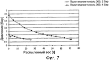
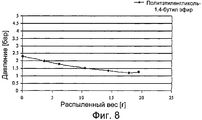
Та же модель эксперимента, которая была использована для фиг.4-6, позволяет при заданной постоянной температуре определить зависимость давления в газовой фазе от общего количества добавленного диоксида углерода.The same experimental model that was used for FIGS. 4-6 allows for a given constant temperature to determine the dependence of the pressure in the gas phase on the total amount of added carbon dioxide.
Например, для полиэтиленгликоля 300 при 25°С были получены следующие значения:For example, for polyethylene glycol 300 at 25 ° C, the following values were obtained:
![]()
![]()
Подстановкой значений ![]()
![]()
На фиг.7 и 8 изображена зависимость давления Р в камере для газа-вытеснителя аэрозольных баллонов (аэрозольных банок) согласно настоящему изобретению как функцию от распыленного объема ΔV. Жидкая фаза, свободная от диоксида углерода, была помещена в смесительный цилиндр, выдерживающий максимальное давление в 10 бар, и закрыта. Посредством клапана с встроенной заглушкой к жидкой фазе был добавлен СO2. Для насыщения жидкой фазы СO2 подавали до тех пор, пока в смесительном цилиндре не было достигнуто давление в 10 бар. Клапан был закрыт и смесительный цилиндр подвергнут тщательному встряхиванию до тех пор, пока давление не стало постоянным даже при встряхивании. Затем снова подавали СO2. Эта процедура повторялась до тех пор, пока желаемое давление в смесительном цилиндре не стало постоянным даже при встряхивании. С использованием помпы заранее подготовленный таким образом газ-вытеснитель, содержащий 5 весовых процентов диоксида углерода, был накачан без газовой фазы в устройство для наполнения («Pamasol») и подан в серийно выпускаемый контейнер с внутренним мешком. Номинальный объем контейнера составлял в каждом случае 118 мл, объем внутреннего мешка составлял 60 мл, и количество введенного газа-вытеснителя составляло 12 г на контейнер. Для имитации распыляемого содержимого контейнера внутренний мешок был наполнен водой посредством устройства для наполнения. Возможные значения начального давления на фиг.7 и 8 изображены на оси у. Вода из контейнера была распылена, и давление как функция потери веса контейнера (1 г потерянного веса = 1 мл распыленного объема вещества) было измерено и нанесено на график.Figures 7 and 8 show the dependence of the pressure P in the chamber for a propellant of aerosol cans (aerosol cans) according to the present invention as a function of the atomized volume ΔV. The liquid phase, free of carbon dioxide, was placed in a mixing cylinder, withstanding a maximum pressure of 10 bar, and closed. By means of a valve with an integrated plug, CO 2 was added to the liquid phase. To saturate the liquid phase, CO 2 was supplied until a pressure of 10 bar was reached in the mixing cylinder. The valve was closed and the mixing cylinder was thoroughly shaken until the pressure became constant even with shaking. Then, CO 2 was again fed. This procedure was repeated until the desired pressure in the mixing cylinder became constant even with shaking. Using a pump, a propellant prepared in such a way, containing 5 weight percent carbon dioxide, was pumped without a gas phase into a filling device (“Pamasol”) and fed into a commercially available container with an inner bag. The nominal volume of the container in each case was 118 ml, the volume of the inner bag was 60 ml, and the amount of propellant introduced was 12 g per container. To simulate the sprayed contents of the container, the inner bag was filled with water through a filling device. Possible values of the initial pressure in Figs. 7 and 8 are shown on the y axis. Water from the container was sprayed, and pressure as a function of weight loss of the container (1 g of lost weight = 1 ml of atomized volume of substance) was measured and plotted.
Claims (26)
а) газовой фазы (5), содержащей диоксид углерода, и
б) жидкой фазы (6), содержащей соединение, выбранное из группы, состоящей из полиэтиленгликолей и их (С1-С4) моноэфиров, и (C1-C4) диэфиров, а также растворенный в них диоксид углерода.1. A high pressure cylinder for storing the compressed substance (7, 9) in a gaseous, liquid or finely divided state, said high pressure cylinder comprising: a wall (1), the inner side of which defines the interior of the high pressure cylinder; the separating part (2, 12) located in the inner space and dividing the inner space into a storage chamber (3) and a chamber (4) for a propellant, the storage chamber containing a substance (7, 9) and a chamber (4) for of the propellant contains a propellant, and the separating part (2, 12) is configured to impermeable to liquids separation of the chamber (3) for storage and the chamber (4) for the propellant, and is configured to change the ratio under the influence of the propellant between the volume of the chamber (3) for storage and measures (4) for the propellant in favor of the chamber (4) for the propellant; and wherein the high pressure cylinder is characterized in that the propellant consists of:
a) a gas phase (5) containing carbon dioxide, and
b) a liquid phase (6) containing a compound selected from the group consisting of polyethylene glycols and their (C 1 -C 4 ) monoesters, and (C 1 -C 4 ) diesters, as well as carbon dioxide dissolved in them.
разделяющая часть представляет собой подвижный поршень (12), точно прилегающий к внутренней поверхности стенки и выполненный с возможностью изменения соотношения объема камеры (3) для хранения и камеры (4) для газа-вытеснителя посредством движения вдоль упомянутого отрезка центральной оси.3. The high-pressure cylinder according to claim 1, in which the inner space has a central axis, wherein a cross section perpendicular to said central axis, for at least a continuous length of said central axis, has a constant shape and surface area; and
the separating part is a movable piston (12), precisely adjacent to the inner surface of the wall and configured to change the ratio of the volume of the storage chamber (3) and the propellant chamber (4) by moving along the said central axis.
а) газовой фазы (5), содержащей диоксид углерода, и
б) жидкой фазы (6), содержащей более 90 вес.%, в предпочтительном варианте выполнения, по меньшей мере, 95 вес.%, а в особенно предпочтительном варианте выполнения, по меньшей мере, 98 вес.% жидкой фазы (6), полиэтиленгликоля и диоксида углерода, растворенного в нем; при условии, что полиэтиленгликоль не является полиэтиленгликолем 400.18. Propellant gas consisting of:
a) a gas phase (5) containing carbon dioxide, and
b) a liquid phase (6) containing more than 90 wt.%, in a preferred embodiment, at least 95 wt.%, and in a particularly preferred embodiment, at least 98 wt.% of the liquid phase (6), polyethylene glycol and carbon dioxide dissolved in it; provided that the polyethylene glycol is not polyethylene glycol 400.
Applications Claiming Priority (2)
| Application Number | Priority Date | Filing Date | Title |
|---|---|---|---|
| CH7242006 | 2006-05-04 | ||
| CH724/06 | 2006-05-04 |
Publications (2)
| Publication Number | Publication Date |
|---|---|
| RU2008148122A RU2008148122A (en) | 2010-06-10 |
| RU2430003C2 true RU2430003C2 (en) | 2011-09-27 |
Family
ID=37309440
Family Applications (1)
| Application Number | Title | Priority Date | Filing Date |
|---|---|---|---|
| RU2008148122/12A RU2430003C2 (en) | 2006-05-04 | 2007-05-03 | High-pressure cylinder containing carbon dioxide and polyethylene glycol as propellant gas |
Country Status (9)
| Country | Link |
|---|---|
| US (1) | US8240509B2 (en) |
| EP (1) | EP2013114B1 (en) |
| AT (1) | ATE465101T1 (en) |
| CA (1) | CA2651096C (en) |
| DE (1) | DE502007003514D1 (en) |
| DK (1) | DK2013114T3 (en) |
| ES (1) | ES2345009T3 (en) |
| RU (1) | RU2430003C2 (en) |
| WO (1) | WO2007128157A1 (en) |
Cited By (1)
| Publication number | Priority date | Publication date | Assignee | Title |
|---|---|---|---|---|
| RU2692223C2 (en) * | 2014-03-28 | 2019-06-21 | Ц.Х.&И. Течнологиес, Инц. | Repeatedly filled aerosol cartridge |
Families Citing this family (10)
| Publication number | Priority date | Publication date | Assignee | Title |
|---|---|---|---|---|
| NL1034895C2 (en) * | 2008-01-08 | 2009-07-13 | Dispensing Technologies Bv | Composite container and method for manufacturing thereof. |
| EP2165968A1 (en) | 2008-09-19 | 2010-03-24 | InBev S.A. | Bag-in-container with prepressurized space between inner bag and outer container |
| CH706042A1 (en) * | 2012-01-27 | 2013-07-31 | Alpla Werke | Pressure vessel. |
| DE102012221448A1 (en) * | 2012-11-23 | 2014-06-12 | Hochschule Aalen | Magnetic material and process for its production |
| JP5798220B2 (en) * | 2013-12-12 | 2015-10-21 | 株式会社ヒロマイト | Manufacturing method of double structure container |
| JP6630491B2 (en) * | 2015-05-01 | 2020-01-15 | 株式会社ダイゾー | Discharge container |
| US10519923B2 (en) * | 2015-09-21 | 2019-12-31 | Ut-Battelle, Llc | Near isothermal combined compressed gas/pumped-hydro electricity storage with waste heat recovery capabilities |
| CN105541523B (en) * | 2015-12-15 | 2017-11-10 | 湖北航天化学技术研究所 | A kind of hydrocarbon propellant compositions of thermoplasticity |
| EP3655346B1 (en) | 2017-07-17 | 2021-12-22 | Rocep Lusol Holdings Limited | Dispensing apparatus |
| US12037996B2 (en) | 2020-09-29 | 2024-07-16 | Ut-Battelle, Llc | Fuel driven near isothermal compressor |
Family Cites Families (11)
| Publication number | Priority date | Publication date | Assignee | Title |
|---|---|---|---|---|
| US3031347A (en) * | 1951-02-05 | 1962-04-24 | Aerojet General Co | Slow burning solid composite propellant |
| JPS5493214A (en) * | 1977-12-29 | 1979-07-24 | Toppan Printing Co Ltd | Aerosol container made of plastic |
| FR2447445A1 (en) | 1979-01-25 | 1980-08-22 | Chaumat Bernard | DOOR DEVICE OR THE LIKE |
| JPS60110669A (en) * | 1983-11-12 | 1985-06-17 | 株式会社林原生物化学研究所 | Pressure discharging vessel and manufacture thereof |
| FR2622541B1 (en) * | 1987-10-30 | 1990-03-09 | Oreal | |
| JPH03124585A (en) * | 1989-10-09 | 1991-05-28 | Yoshida Kogyo Kk <Ykk> | Pressurized discharge container for fluid substance |
| US5167347A (en) * | 1991-04-22 | 1992-12-01 | Clairol Incorporated | Multi-fluid mixing and automatic metering dispenser |
| RU2016820C1 (en) * | 1991-06-29 | 1994-07-30 | Анатолий Яковлевич Столяревский | Method for producing excess pressure of gaseous carbon dioxide inside working volume of package |
| EP0776834A1 (en) | 1995-11-29 | 1997-06-04 | Viorica Dipl.-Ing. Muntean | Container for dispensing aerosols or foams |
| JP4666716B2 (en) * | 2000-05-26 | 2011-04-06 | 株式会社ダイゾー | Aerosol products |
| FR2824539B1 (en) * | 2001-05-09 | 2003-12-19 | Oreal | DEVICE FOR THE SEPARATE PACKAGING OF TWO PRODUCTS, AND THEIR DISPENSING UNDER PRESSURE, SEPARATELY OR MIXED |
-
2007
- 2007-05-03 WO PCT/CH2007/000221 patent/WO2007128157A1/en active Application Filing
- 2007-05-03 AT AT07720118T patent/ATE465101T1/en active
- 2007-05-03 US US12/299,414 patent/US8240509B2/en not_active Expired - Fee Related
- 2007-05-03 EP EP07720118A patent/EP2013114B1/en active Active
- 2007-05-03 DK DK07720118.4T patent/DK2013114T3/en active
- 2007-05-03 DE DE502007003514T patent/DE502007003514D1/en active Active
- 2007-05-03 RU RU2008148122/12A patent/RU2430003C2/en not_active IP Right Cessation
- 2007-05-03 ES ES07720118T patent/ES2345009T3/en active Active
- 2007-05-03 CA CA2651096A patent/CA2651096C/en not_active Expired - Fee Related
Cited By (1)
| Publication number | Priority date | Publication date | Assignee | Title |
|---|---|---|---|---|
| RU2692223C2 (en) * | 2014-03-28 | 2019-06-21 | Ц.Х.&И. Течнологиес, Инц. | Repeatedly filled aerosol cartridge |
Also Published As
| Publication number | Publication date |
|---|---|
| ES2345009T3 (en) | 2010-09-13 |
| RU2008148122A (en) | 2010-06-10 |
| CA2651096A1 (en) | 2007-11-15 |
| EP2013114A1 (en) | 2009-01-14 |
| WO2007128157A1 (en) | 2007-11-15 |
| US20090184131A1 (en) | 2009-07-23 |
| EP2013114B1 (en) | 2010-04-21 |
| CA2651096C (en) | 2014-07-08 |
| DE502007003514D1 (en) | 2010-06-02 |
| US8240509B2 (en) | 2012-08-14 |
| ATE465101T1 (en) | 2010-05-15 |
| DK2013114T3 (en) | 2010-08-16 |
Similar Documents
| Publication | Publication Date | Title |
|---|---|---|
| RU2430003C2 (en) | High-pressure cylinder containing carbon dioxide and polyethylene glycol as propellant gas | |
| US2815152A (en) | Dispensing package and method | |
| US4202470A (en) | Pressurized dispensers for dispensing products utilizing a pressure transfer fluid | |
| US4969577A (en) | Apparatus to provide for the storage and the controlled delivery of products that are under pressure | |
| AU2007323596B2 (en) | Carbon filled pressurized container and method of making same | |
| US6230943B1 (en) | Aerosol product and method for manufacturing the same | |
| US20140131395A1 (en) | Packaged products including a personal care medium and a non-flammable volatile agent stored within an aerosol container | |
| US20110192865A1 (en) | Dispenser | |
| US11383917B2 (en) | Aerosol product | |
| WO1983001244A1 (en) | Pressurized dispensing apparatus | |
| CN107428457A (en) | Structures and methods closed component being sealed on the bottleneck of plastic pressure container | |
| US3235137A (en) | Pressurized dispensing container | |
| US3245435A (en) | Pressurized dispenser with propellant bag | |
| JPH05254579A (en) | Pressurized dispensing device | |
| US3232324A (en) | Method and apparatus for filling aerosol dispensers | |
| CN1245470A (en) | Gas generating unit | |
| JP4067626B2 (en) | Aerosol products and process | |
| JPH04371251A (en) | Piston-containing pressure vessel | |
| JPH02157057A (en) | Double wall container | |
| JPH05229579A (en) | Piston-containing pressure container | |
| JPS61153170A (en) | Aerosol for pack | |
| Paine | Aerosols (pressurized containers) | |
| EP4101786A1 (en) | Dispensing apparatus | |
| JP2006264785A (en) | Aerosol container body and aerosol container | |
| CA2664508A1 (en) | Improved aerosol and other propellant style pressurized can product delivery system |
Legal Events
| Date | Code | Title | Description |
|---|---|---|---|
| MM4A | The patent is invalid due to non-payment of fees |
Effective date: 20200504 |