RU2425894C1 - Method of later thermal processing of complex surfaces of large-sized parts - Google Patents
Method of later thermal processing of complex surfaces of large-sized parts Download PDFInfo
- Publication number
- RU2425894C1 RU2425894C1 RU2009146753/02A RU2009146753A RU2425894C1 RU 2425894 C1 RU2425894 C1 RU 2425894C1 RU 2009146753/02 A RU2009146753/02 A RU 2009146753/02A RU 2009146753 A RU2009146753 A RU 2009146753A RU 2425894 C1 RU2425894 C1 RU 2425894C1
- Authority
- RU
- Russia
- Prior art keywords
- laser
- hardening
- tracks
- processing
- parallel
- Prior art date
Links
Images


Abstract
Description
Область техникиTechnical field
Изобретение относится к металлургии, а именно к термообработке поверхности материалов концентрированными источниками энергии, и может быть использовано в машиностроении для повышения износостойкости деталей, увеличения производительности обработки.The invention relates to metallurgy, namely to heat treatment of the surface of materials with concentrated energy sources, and can be used in mechanical engineering to increase the wear resistance of parts, increase processing productivity.
Уровень техникиState of the art
При изготовлении штампов и пресс-форм для литья под давлением они подвергаются термической обработке с целью повышения износостойкости рабочих поверхностей, работающих в условиях повышенных нагрузок и трения.In the manufacture of dies and molds for injection molding, they are heat treated in order to increase the wear resistance of work surfaces operating under conditions of increased loads and friction.
Существующая технология изготовления крупногабаритных матриц и пуансонов требует наличие больших закалочных печей, связанных с большими затратами электроэнергии и ручного труда. При термообработке крупногабаритных пространственно сложных деталей часто на стадии охлаждения из-за неравномерного теплоотвода с отдельных участков поверхности возникают трещины, что приводит к большому проценту брака дорогостоящих изделий, но основной недостаток существующей технологии заключается в том, что получаемая при объемной термической обработке твердость не достаточна для обеспечения высокой стойкости и работоспособности штампа (Коваленко B.C. и др. Лазерное и электроэрозионное упрочнение материалов. - М.: Наука, 1986, с.239-245). Для повышения твердости рабочих кромок штампа используют различные методы, наиболее эффективным из них является метод лазерного термоупрочнения.The existing technology for the manufacture of large-sized dies and punches requires large quenching furnaces, associated with high costs of electricity and manual labor. During the heat treatment of large spatially complex parts, often cracks occur due to uneven heat removal from individual surface sections, which leads to a large percentage of defective products, but the main disadvantage of the existing technology is that the hardness obtained by volumetric heat treatment is not sufficient for ensuring high durability and operability of the stamp (Kovalenko BC et al. Laser and electroerosive hardening of materials. - M .: Nauka, 1986, p.239-245). To increase the hardness of the working edges of the stamp, various methods are used, the most effective of which is the method of laser thermal hardening.
Это обусловлено высокой производительностью труда, локальным нагревом места обработки и охлаждения этого участка с критической скоростью после прекращения воздействия лазерного луча за счет теплоотвода во внутренние слои металла. Этот процесс характеризуется малым временем воздействия и обеспечивает отсутствие деформации деталей в отличие от закалки токами высокой частоты, электронагревом, закалкой из расплава и не требует применять какие-либо охлаждающие среды.This is due to high labor productivity, local heating of the processing and cooling site of this section at a critical speed after the termination of the laser beam due to heat removal to the inner layers of the metal. This process is characterized by a short exposure time and ensures the absence of deformation of parts, in contrast to quenching by high-frequency currents, electric heating, quenching from the melt and does not require the use of any cooling medium.
Суть лазерного термоупрочнения заключается в воздействии интенсивного потока лазерного изучения на локальный участок поверхности, поглощении лазерного излучения в приповерхностных участках материалов и, вследствие этого, быстром разогреве этих участков до высоких температур. После прекращения действия излучения нагретый участок охлаждается в основном вследствие теплопроводности во внутренние объемы материала, а также за счет теплоотдачи с поверхности.The essence of laser thermal hardening is the effect of an intense laser study flow on a local surface area, the absorption of laser radiation in the surface areas of materials, and, as a result, the rapid heating of these areas to high temperatures. After the cessation of radiation, the heated area is cooled mainly due to thermal conductivity in the internal volumes of the material, as well as due to heat transfer from the surface.
Известен способ лазерной термообработки, заключающийся в формировании зоны термической обработки за несколько проходов луча лазера с перекрывающимися зонами, сфокусированного в световое пятно лазерного излучения (Головко Л.Ф. и др. Обеспечение качества слоев, полученных лазерной наплавкой или упрочняющей обработкой. Автоматическая сварка. 2001, №12, с.47-52).A known method of laser heat treatment, which consists in the formation of a heat treatment zone for several passes of the laser beam with overlapping zones, focused in the light spot of the laser radiation (Golovko LF and others. Quality assurance of the layers obtained by laser welding or hardening. Automatic welding. 2001 No. 12, p. 47-52).
Известен способ поверхностной закалки металлов лучом лазера, при котором режим обработки регулируют изменением энергии импульса, его длительности и диаметра пятна, считая, что распределение энергии по пятну близко к равномерному (Сафонов А.Н. и др. Лазерное термоупрочнение режущего инструмента: обзорн. информ. - М: ВНИПИЭИлеспром, 1989, с.52).A known method of surface hardening of metals by a laser beam, in which the processing mode is regulated by changing the pulse energy, its duration and the diameter of the spot, assuming that the energy distribution over the spot is close to uniform (Safonov AN, et al. Laser thermal hardening of a cutting tool: overview inform . - M: VNIPIEIlesprom, 1989, p. 52).
Известен способ лазерной термической обработки материалов при помощи непрерывного лазерного излучения, сфокусированного в световое пятно в виде отрезка, перемещаемого по заданной траектории с постоянной или переменной скоростью, при этом предварительно определяют допустимую максимальную температуру на поверхности обрабатываемого материала, превышающую температуру необходимого структурного или фазового превращения (RU 2345148 C2, от 27.01.2009 г.).A known method of laser heat treatment of materials using continuous laser radiation focused into a light spot in the form of a segment that moves along a given path with constant or variable speed, while the allowable maximum temperature on the surface of the processed material is previously determined, exceeding the temperature of the required structural or phase transformation ( RU 2345148 C2, dated January 27, 2009).
В ряде зарубежных заявок (DE-OS-4217530, DE-OS-3922377, ЕР-А-0419999, US-A-4,825,035) представлены методы лазерного термоупрочнения высоконапряженных металлических поверхностей, например рабочих поверхностей поршня.A number of foreign applications (DE-OS-4217530, DE-OS-3922377, EP-A-0419999, US-A-4,825,035) provide laser thermal hardening methods for highly stressed metal surfaces, for example, piston working surfaces.
Наиболее близким по технической сущности к предлагаемому способу является способ упрочнения штампа, заявленный в патенте (RU 2033435 от 20.04.1995 г.).The closest in technical essence to the proposed method is a method of hardening a stamp, as claimed in the patent (RU 2033435 from 04.20.1995).
Сущность изобретения: после объемной термической обработки пуансона и матрицы упрочняют их рабочие кромки непрерывным излучением лазера. При этом лазерные дорожки упрочнения наносят в направлении от центра пуансона или от периферии матрицы к режущим кромкам перпендикулярно их контуру с шагом S=(0,8-0,85)d, где d - диаметр пятна лазерного луча на поверхности детали. Недостатком способа является то, что при обработке вертикальных и наклонных поверхностей расплавленный металл начинает стекать по обрабатываемой поверхности. Это явление обусловлено тем, что сила тяжести образующихся расплавленных капель не уравновешивается силой натяжения самой капки. В силу этого ухудшается процесс кристаллизации расплавленного металла, что приводит к неоднородности обработки, снижает качество обработки деталей. Более того, последовательное нанесение дорожек упрочнения с перекрытием вызывает перегрев металла, что приводит к прожогам, т.е. также снижает качество деталей.The inventive after volumetric heat treatment of the punch and matrix reinforce their working edges by continuous laser radiation. In this case, laser hardening tracks are applied in the direction from the center of the punch or from the periphery of the matrix to the cutting edges perpendicular to their contour with a step S = (0.8-0.85) d, where d is the diameter of the laser beam spot on the surface of the part. The disadvantage of this method is that when processing vertical and inclined surfaces, the molten metal begins to flow down the treated surface. This phenomenon is due to the fact that the gravity of the formed molten droplets is not balanced by the tension force of the cup itself. Due to this, the process of crystallization of molten metal is worsened, which leads to heterogeneity of processing, reduces the quality of processing of parts. Moreover, the sequential application of hardening tracks with overlapping causes overheating of the metal, which leads to burnouts, i.e. also reduces the quality of parts.
Кроме того, упрочнение выполняют с помощью лазерной технологической установки «Латус-31», представляющей собой установку импульсного газового лазера, снабженную двухкоординатным столом, предназначенным для установки детали и перемещения ее. Т.е. для обработки сложных деталей требуется дополнительное оборудование, например специальные вращатели, позволяющие обеспечить перпендикулярность луча лазера к обрабатываемой поверхности. А детали со сложными криволинейными поверхностями вообще не поддаются лазерному упрочнению, поскольку выпускаемые в настоящее время в РФ лазерные установки имеют двухкоординатные столы и предназначены для обработки плоских деталей и простейших цилиндрических вращательных поверхностей за счет отдельно поставляемых вращателей. Например, установки фирмы ЗАО Лазерные комплексы ТЛ-700, ТЛ-1.5 (Проспект фирмы ЗАО «Лазерные комплексы» с выставки «Металлообработка - 2009»).In addition, hardening is performed using the Latus-31 laser processing unit, which is a pulsed gas laser unit equipped with a two-coordinate table designed to install the part and move it. Those. for the processing of complex parts, additional equipment is required, for example, special rotators to ensure the perpendicularity of the laser beam to the surface to be treated. And parts with complex curved surfaces do not lend themselves to laser hardening at all, since the laser systems currently manufactured in the Russian Federation have two-coordinate tables and are designed to process flat parts and simple cylindrical rotary surfaces due to separately supplied rotators. For example, installations of the company Laser Complexes TL-700, TL-1.5 (Prospectus of the company Laser Complexes CJSC from the exhibition Metalworking - 2009).
Таким образом, все представленные способы и устройства имеют существенный недостаток, а именно они не могут быть использованы для обработки трехмерных деталей со сложной поверхностью, существенными габаритами и большим весом, когда манипулирование деталью затруднено.Thus, all the presented methods and devices have a significant drawback, namely, they cannot be used for processing three-dimensional parts with a complex surface, substantial dimensions and heavy weight, when manipulating the part is difficult.
Сущность изобретения.SUMMARY OF THE INVENTION
Задача предлагаемого изобретения состоит в разработке технологии лазерной термообработки деталей со сложной 3D-поверхностью, большим весом и габаритами.The objective of the invention is to develop a technology for laser heat treatment of parts with complex 3D surface, large weight and dimensions.
Кроме того, технология должна обеспечить повышение качества обработки таких деталей.In addition, the technology should provide an increase in the quality of processing of such parts.
Более того, технология должна обладать высокой производительностью и обеспечить снижение себестоимости обработки.Moreover, the technology must have high productivity and ensure a reduction in the cost of processing.
Поставленная цель достигается тем, что в способе лазерного упрочнения сложных пространственных поверхностей, преимущественно крупногабаритных деталей, включающем воздействие непрерывным лазерным лучом, сфокусированным в световое пятно, на поверхность детали и нанесение параллельных дорожек упрочнения с перекрытием путем перемещения светового пятна с постоянной линейной скоростью, нанесение параллельных дорожек упрочнения на вертикальных или наклонных поверхностях осуществляют лучом, направленным на обрабатываемую поверхность под углом, повернутым от перпендикуляра к поверхности вверх в плоскости обработки детали на угол, равный 0.5-5°, и при увеличенном расходе технологического газа через сопло.This goal is achieved by the fact that in the method of laser hardening of complex spatial surfaces, mainly large parts, comprising applying a continuous laser beam focused in the light spot onto the surface of the part and applying parallel hardening tracks with overlapping by moving the light spot with a constant linear speed, applying parallel hardening tracks on vertical or inclined surfaces are carried out by a beam directed to the surface to be treated At an angle turned from the perpendicular to the surface upward in the workpiece plane by an angle equal to 0.5-5 °, and with an increased flow of process gas through the nozzle.
Кроме того, нанесение параллельных дорожек упрочнения осуществляют попеременно в различных полосах упрочнения, отстоящих друг от друга на расстоянии, достаточном для остывания дорожек при установленных скоростях обработки.In addition, the application of parallel hardening tracks is carried out alternately in different hardening strips, spaced from each other at a distance sufficient to cool the tracks at the set processing speeds.
Более того, нанесение параллельных дорожек упрочнения осуществляют лазерной установкой, снабженной 5-координатной лазерной головкой.Moreover, the application of parallel hardening tracks is carried out by a laser unit equipped with a 5-axis laser head.
Такое выполнение способа позволяет проводить качественную лазерную термообработку сложных и громоздких деталей с увеличенной производительностью.This embodiment of the method allows for high-quality laser heat treatment of complex and bulky parts with increased productivity.
Перечень фигур на чертежах.The list of figures in the drawings.
Изобретение поясняется чертежами, на которых:The invention is illustrated by drawings, in which:
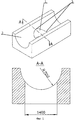
Фиг.1 - показывает общий вид обрабатываемой детали;Figure 1 - shows a General view of the workpiece;
Фиг.2 - показывает схему обработки вертикальной цилиндрической поверхности;Figure 2 - shows a processing diagram of a vertical cylindrical surface;
Фиг.3 - показывает схему обработки горизонтальной цилиндрической поверхности;Figure 3 - shows a processing diagram of a horizontal cylindrical surface;
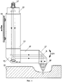
Фиг.4 - показывает общий вид лазерной фокусирующей головки.Figure 4 - shows a General view of the laser focusing head.
Осуществление изобретенияThe implementation of the invention
Сам способ лазерной термообработки деталей сложной пространственной формы заключается в следующем.The very method of laser heat treatment of parts with complex spatial shapes is as follows.
Способ включает воздействие непрерывным лазерным лучом, сфокусированным в световое пятно, на поверхность детали и нанесение параллельных дорожек упрочнения с перекрытием путем перемещения светового пятна с постоянной линейной скоростью.The method includes applying a continuous laser beam focused into a light spot onto the surface of the part and applying parallel hardening tracks with overlapping by moving the light spot with a constant linear speed.
Упрочняемая поверхность детали подвергается воздействию непрерывным лазерным излучением λ=1,07 мкм, сфокусированным в световое пятно, причем диаметр пятна выбирается таким, чтобы плотность мощности была достаточна для соответствующих фазовых превращений (согласно диаграмме железо-углерод) ~106 т/см2, т.е. имело место полной фазовой перекристаллизации с образованием аустенитной структуры, которая после прекращения лазерного нагрева данного объема стали превращается в мартенсит.The hardened surface of the part is exposed to continuous laser radiation λ = 1.07 μm focused into a light spot, and the spot diameter is chosen so that the power density is sufficient for the corresponding phase transformations (according to the iron-carbon diagram) ~ 10 6 t / cm 2 , those. There was a complete phase recrystallization with the formation of an austenitic structure, which, after the cessation of laser heating of a given volume of steel, turns into martensite.
Причем размер пятна и расстояние до обрабатываемой поверхности по всей траектории должно быть постоянным, такое перемещение называют дорожкой.Moreover, the spot size and the distance to the surface to be treated along the entire path should be constant, this movement is called a track.
Расчет температурных полей при лазерной поверхностной обработке описан авторами Григорьянцом А.Т., Сафроновым А.Н. в книге «Методы поверхностной лазерной обработки. Лазерная техника и технология», - М.: Высшая школа, 1987, с.15-27.Calculation of temperature fields during laser surface treatment is described by the authors Grigoryants A.T., Safronov A.N. in the book “Methods of surface laser processing. Laser technique and technology ”, - M .: Higher School, 1987, p.15-27.
С помощью пятикоординатной головки лазерное излучение, сфокусированное в пятно, перемещается по рабочей упрочняемой поверхности штампа от одного его конца до другого перпендикулярно контуру с постоянной линейной скоростью при обработке горизонтальных или близких к горизонтальным поверхностям детали.Using a five-coordinate head, laser radiation focused into the spot moves along the working hardened surface of the stamp from one end to the other perpendicular to the contour with a constant linear speed when processing horizontal or close to horizontal surfaces of the part.
Последовательность проходов (дорожек) осуществляется в следующем порядке. После прохождения первой дорожки в первой полосе упрочнения лазерная головка перемещается на величину порядка 30S к другой дорожке - в другой полосе упрочнения, где S - шаг между соседними дорожками, равный (0,8÷0,9)d (d - диаметр сфокусированного пятна). Затем, через такое же расстояние, к третьей дорожке в третьей полосе упрочнения и т.д. до конца обрабатываемой поверхности. После чего лазерная головка возвращается с шагом S к первой дорожке и так цикл повторяется, пока не будет обработана вся поверхность. Такая последовательность дорожек удовлетворяет условию полного температурного остывания обработанного материала при каждом проходе дорожки. При этих параметрах глубина упрочненного слоя составляет ~2 мм для инструментальных сталей.The sequence of passes (tracks) is carried out in the following order. After passing the first track in the first hardening band, the laser head moves by an amount of the order of 30S to another track in another hardening band, where S is the step between adjacent tracks equal to (0.8 ÷ 0.9) d (d is the diameter of the focused spot) . Then, through the same distance, to the third track in the third hardening band, etc. to the end of the work surface. After that, the laser head returns with step S to the first track, and so the cycle repeats until the entire surface is processed. This sequence of tracks satisfies the condition of complete temperature cooling of the processed material with each passage of the track. With these parameters, the depth of the hardened layer is ~ 2 mm for tool steels.
Таким образом, нанесение параллельных дорожек упрочнения осуществляют попеременно в различных полосах упрочнения, отстоящих друг от друга на расстоянии, достаточном для остывания дорожек (при установленных скоростях обработки).Thus, the application of parallel hardening tracks is carried out alternately in different hardening strips, spaced from each other at a distance sufficient to cool the tracks (at set processing speeds).
Но главной преградой при термообработке сложных пространственных форм является обработка вертикальных и наклонных поверхностей, при упрочнении которых расплавленный металл начинает стекать по обрабатываемой поверхности. Это явление обусловлено тем, что сила тяжести образующихся расплавленных капель не уравновешивается силой натяжения самой капли.But the main obstacle in the heat treatment of complex spatial forms is the treatment of vertical and inclined surfaces, during hardening of which the molten metal begins to flow down the surface to be treated. This phenomenon is due to the fact that the gravity of the formed molten droplets is not balanced by the tension force of the droplet itself.
Для предотвращения дефектов обработки нанесение параллельных дорожек упрочнения на вертикальных или наклонных поверхностях осуществляют лучом, направленным на обрабатываемую поверхность под углом, отличным от перпендикуляра, т.е. повернутым от перпендикуляра к поверхности вверх в плоскости обработки детали на угол, равный 0.5-5°. При этом малые углы поворота луча соответствуют поверхностям с малым углом наклона, в то время как большие углы выбирают для обработки крутых и вертикальных поверхностей.To prevent processing defects, the application of parallel hardening tracks on vertical or inclined surfaces is carried out by a beam directed to the surface to be machined at an angle different from the perpendicular, i.e. turned from the perpendicular to the surface up in the plane of the workpiece by an angle equal to 0.5-5 °. In this case, small angles of rotation of the beam correspond to surfaces with a small angle of inclination, while large angles are chosen for processing steep and vertical surfaces.
При этом обработку ведут при увеличенном расходе технологического газа через сопло. Необходима подача технологического газа под давлением от 0.5 до 2.5 атм, осуществляемая через сопло фокусирующей головки, соосно лазерному излучению. Это делается для того, чтобы давление подаваемого технологического газа способствовало быстрейшей кристаллизации расплавленного металла и уравновешивало силу тяжести самой капли.In this case, the treatment is carried out with an increased flow of process gas through the nozzle. It is necessary to supply the process gas under pressure from 0.5 to 2.5 atm, carried out through the nozzle of the focusing head, coaxially with laser radiation. This is done so that the pressure of the supplied process gas promotes the fastest crystallization of the molten metal and balances the gravity of the drop itself.
Регулирование расхода технологического газа и угла наклона головки подбирается из условия равновесия всех сил, действующих на образовавшуюся при лазерном нагреве капле расплава.The regulation of the flow rate of the process gas and the angle of inclination of the head is selected from the condition of equilibrium of all the forces acting on the drop of melt formed during laser heating.
Такое энергетическое воздействие на поверхность, а также равномерное распределение плотности мощности в самом пятне, обусловленное конструкцией волоконного лазера, исключает такие дефекты, как пережеги, локальное оплавление, неравномерная глубина обработки. Что, таким образом, позволяет бороться с главным недостатком лазерной термообработки - неравномерным распределением механических свойств по ширине зоны термического влияния, которое часто приводит к хрупкости тонких изделий вследствие перегрева центральной и недостаточной твердости в результате недогрева периферийной области лазерного воздействия.Such an energy effect on the surface, as well as a uniform distribution of the power density in the spot itself, due to the design of the fiber laser, eliminates such defects as burns, local fusion, and uneven processing depth. This, therefore, allows us to deal with the main disadvantage of laser heat treatment - the uneven distribution of mechanical properties over the width of the heat-affected zone, which often leads to the fragility of thin products due to overheating of the central and insufficient hardness as a result of overheating of the peripheral region of the laser exposure.
Нанесение параллельных дорожек упрочнения осуществляют лазерной установкой, снабженной 5-координатной лазерной головкой, которая крепится в суппорте лазерного комплекса с возможностью перемещать ее по трем координатам, а сама головка имеет возможность вращаться n×360° вокруг вертикальной оси (координата С) и поворачиваться на угол ±120° вдоль горизонтальной оси (координата В) с помощью круговых синхронных двигателей, расположенных непосредственно в самой головке. Излучение иттербиевого волоконного лазера транспортируется в лазерную фокусирующую головку с помощью волоконного оптического кабеля.The application of parallel hardening tracks is carried out by a laser system equipped with a 5-axis laser head, which is mounted in the support of the laser complex with the ability to move it in three coordinates, and the head itself has the ability to rotate n × 360 ° around a vertical axis (coordinate C) and rotate through an angle ± 120 ° along the horizontal axis (coordinate B) using circular synchronous motors located directly in the head itself. The radiation of the ytterbium fiber laser is transported to the laser focusing head using a fiber optic cable.
Таким образом, лазерная фокусирующая головка совершает движения в 5-ти координатах, что позволяет обрабатывать сложные пространственные поверхности, при этом сама обрабатываемая деталь остается неподвижной.Thus, the laser focusing head makes movements in 5 coordinates, which allows you to process complex spatial surfaces, while the workpiece itself remains stationary.
Система программного управления лазерным комплексом позволяет установить оптимальный режим работы лазера по таким параметрам, как мощность лазерного излучения, расстояние между оптической фокусирующей головкой и обрабатываемой поверхностью, диаметр сфокусированного пятна лазерного излучения, скорость обработки, угол между поверхностью и оптической осью лазерного луча, количество и последовательность проходов луча по обрабатываемой поверхности и сдвиг между ними, а также подачу и расход технологического газа, подаваемого соосно излучению.The laser complex software control system allows you to establish the optimal laser mode by parameters such as laser power, distance between the optical focusing head and the surface to be treated, diameter of the focused laser spot, processing speed, angle between the surface and the optical axis of the laser beam, number and sequence beam passes along the surface to be treated and the shift between them, as well as the supply and flow of process gas supplied coaxially from radiation.
Для перемещения лазерной фокусирующей головки имеется станочная часть, выполненная в виде портальной конструкции, которая обоснована большой величиной перемещений рабочих органов по координатам Х и Y. Такая компоновка обеспечивает более высокую жесткость.To move the laser focusing head, there is a machine part made in the form of a portal structure, which is justified by the large amount of displacements of the working bodies along the X and Y coordinates. This arrangement provides higher rigidity.
Сама головка крепится к ползуну (см. фиг.4 (поз.10)) и имеет возможность как единое целое передвигаться по координате X, Y со скоростью 100 м/мин, а по координате Z со скоростью 30 м/мин.The head itself is attached to the slider (see figure 4 (pos. 10)) and has the ability to move as a whole unit along the X, Y coordinate at a speed of 100 m / min, and along the Z coordinate at a speed of 30 m / min.
Волоконный оптический кабель (поз.12) служит для транспортировки лазерного излучения λ=1,07 мкм от излучателя к лазерной фокусирующей головке. Длина такого световода может быть до 200 м, энергетические потери при этом составляют менее 1%, а оптическое качество выходящего из коннектора излучения составляет <2,5 мм·мрад, где коннектор - это кварцевый кубик, оптически приваренный к волоконному кабелю, и служит для вывода лазерного излучения. Для большего теплоотвода кварцевый кубик заделан в металлический кожух и охлаждается дистиллированной водой. Сам коннектор прецизионно соединяется с помощью разъема QBH-типа с коллиматором (поз.13).Fiber optic cable (item 12) is used to transport laser radiation λ = 1.07 μm from the emitter to the laser focusing head. The length of such a fiber can be up to 200 m, the energy loss in this case is less than 1%, and the optical quality of the radiation coming out of the connector is <2.5 mm mrad, where the connector is a quartz cube optically welded to a fiber cable and serves output laser radiation. For greater heat removal, the quartz cube is embedded in a metal casing and cooled with distilled water. The connector itself is precision connected using a QBH-type connector to a collimator (key 13).
Коллиматор - это оптический прибор, преобразующий расходящийся пучок лазерного излучения, выходящий из коннектора, в плоскопараллельный, для этого в цилиндрическом корпусе коллиматора закреплен объектив, расположенный на расстоянии фокусной длины от выходного торца коннектора.A collimator is an optical device that converts a diverging laser beam emerging from the connector into a plane-parallel one, for this a lens is mounted in the cylindrical collimator body located at a distance of the focal length from the output end of the connector.
Коллиматор крепится соосно с помощью винтов с цилиндрическим корпусом вертикального электропривода (поз.14), выполненного в виде тороидального синхронного двигателя с полым валом, на конце которого крепится призма с поворотным зеркалом (поз.15). Двигатель позволяет совершать круговые движения призмы с зеркалом вокруг вертикальной оси со скоростью 360 град/с.The collimator is mounted coaxially with screws with a cylindrical casing of the vertical electric drive (pos. 14), made in the form of a toroidal synchronous motor with a hollow shaft, at the end of which a prism with a rotary mirror (pos. 15) is mounted. The engine allows circular movements of a prism with a mirror around a vertical axis at a speed of 360 deg / s.
Двигатель (поз.16) с горизонтальной осью вращения установлен на полом валу и одним концом крепится к призме с поворотным зеркалом (поз.15), а другим к призме с поворотным зеркалом (поз.17) и позволяет поворачивать призму с поворотным зеркалом вокруг горизонтальной оси (координата В) на угол ±120° со скоростью 360 град/с.An engine (pos. 16) with a horizontal axis of rotation is mounted on a hollow shaft and is attached at one end to a prism with a rotary mirror (pos. 15), and the other to a prism with a rotary mirror (pos. 17) and allows you to rotate a prism with a rotary mirror around a horizontal axis (coordinate B) at an angle of ± 120 ° at a speed of 360 deg / s.
Полости внутри вала двигателя (поз.14) и двигателя (поз.16) предназначены для прохождения лазерного излучения в зону обработки, а поворотные зеркала в призмах (поз.15 и 17) позволяют поворачивать лазерный луч на угол 90° и направлять его в оптическую фокусирующую головку. Соосно к торцу призмы (поз.17) крепится фокусирующая головка (поз.18) со штуцером для подачи технологического газа.The cavities inside the motor shaft (pos. 14) and the engine (pos. 16) are designed for laser radiation to pass into the processing zone, and the rotary mirrors in prisms (pos. 15 and 17) allow the laser beam to be rotated through an angle of 90 ° and directed into the optical focusing head. A focusing head (key 18) is mounted coaxially to the end face of the prism (key 17) with a fitting for supplying process gas.
Таким образом, оптическая фокусирующая головка с помощью тороидальных синхронных двигателей имеет возможность поворачиваться вокруг вертикальной оси (координата С) на ±360×n и вокруг горизонтальной оси на угол ±120° (координата В) со скоростью 360 град/с и фокусировать попадающее в нее лазерное излучение на поверхность обрабатывающего изделия сложной пространственной формы (поз.19).Thus, with the help of toroidal synchronous motors, the optical focusing head can rotate around the vertical axis (coordinate C) by ± 360 × n and around the horizontal axis by an angle of ± 120 ° (coordinate B) at a speed of 360 deg / s and focus on it laser radiation on the surface of the processing product of complex spatial shape (key 19).
Устройство работает следующим образом.The device operates as follows.
Обрабатываемое изделие (см. фиг.4 (поз.19)) устанавливается в камере лазерного комплекса в специальное крепежное приспособление, которое строго ориентирует обрабатываемое изделие в определенном положении.The workpiece (see figure 4 (pos.19)) is installed in the camera of the laser complex in a special mounting device that strictly orientates the workpiece in a certain position.
Затем с пульта управления лазерного комплекса включается иттербиевый волоконный лазер, излучение которого транспортируется по оптическому волоконному кабелю (поз.12), проложенному в гибких кабеленесущих цепях координат X, Y и Z в лазерную фокусирующую головку, а именно в QBH-разъем коллиматора (поз.13). Выходящий из коннектора волоконного кабеля (поз.12) расходящийся лазерный луч проходит через коллиматор (поз.13), где он коллимируется с помощью объектива. Далее лазерный луч через полый вал тороидального синхронного двигателя (поз.14) и отверстие в призме (поз.15) попадает на поворотное зеркало, где он поворачивается на угол 90° в горизонтальную плоскость.Then, the ytterbium fiber laser is switched on from the control panel of the laser complex, the radiation of which is transported via an optical fiber cable (pos. 12), laid in flexible cable-bearing chains of coordinates X, Y, and Z to the laser focusing head, namely, to the QBH connector of the collimator (pos. 13). The diverging laser beam emerging from the fiber cable connector (key 12) passes through the collimator (key 13), where it is collimated using a lens. Next, the laser beam through the hollow shaft of the toroidal synchronous motor (pos. 14) and the hole in the prism (pos. 15) hits the rotary mirror, where it rotates through an angle of 90 ° in the horizontal plane.
Повернутое в горизонтальную плоскость излучение распространяется внутри полого вала тороидального синхронного двигателя (поз.16) и отверстия в призме (поз.17) и попадает на зеркало, где оно поворачивается опять на угол 90° и направляется в оптическую фокусирующую головку (поз.18).Radiation turned into a horizontal plane propagates inside the hollow shaft of the toroidal synchronous motor (pos. 16) and the hole in the prism (pos. 17) and hits the mirror, where it again rotates through an angle of 90 ° and is sent to the optical focusing head (pos. 18) .
Затем излучение с помощью линзы оптической фокусирующей головки (поз.18) фокусируется на поверхность обрабатываемого изделия (поз.19).Then, the radiation using the lens of the optical focusing head (key 18) is focused on the surface of the workpiece (key 19).
Соосно с лазерным излучением одновременно в зону обработки подается под давлением через штуцер технологический газ, который позволяет поддерживать необходимый процесс термообработки рабочей поверхности изделия.Coaxially with the laser radiation, the process gas is simultaneously supplied to the treatment zone under pressure through the nozzle, which allows the necessary heat treatment of the working surface of the product to be supported.
Лазерная фокусирующая головка за счет движений по пяти координатам (X, Y, Z, C, B) направляет лазерный луч перпендикулярно к обрабатываемой поверхности изделия (поз.19) либо под небольшим углом к ней (0,5÷5)° при обработке вертикальных и наклонных поверхностей.The laser focusing head, by moving along five coordinates (X, Y, Z, C, B), directs the laser beam perpendicular to the workpiece surface (item 19) or at a slight angle to it (0.5 ÷ 5) ° when processing vertical and inclined surfaces.
Система числового программного управления (СЧПУ) с помощью имеющихся приводов позволяет поддерживать фокусное расстояние постоянным по всей обрабатываемой поверхности, а также управлять скоростью обработки, параметрами лазерного луча (мощностью, диаметром сфокусированного пятна), углом между поверхностью и оптической осью лазерного луча для наклонных и вертикальных поверхностей, количеством и последовательностью проходов, смещением между ними, расходом технологического газа во время самого процесса термообработки. Это очень важно для обработки вертикальных поверхностей, так как расплавленный металл может стекать с обрабатываемой поверхности, а подача технологического газа под нужным углом и давлением позволяет контролировать этот процесс.Using the numerical control system (CNC), using the available drives, it is possible to maintain the focal length constant over the entire machined surface, as well as control the processing speed, parameters of the laser beam (power, diameter of the focused spot), the angle between the surface and the optical axis of the laser beam for inclined and vertical surfaces, the number and sequence of passes, the displacement between them, the flow rate of the process gas during the heat treatment process itself. This is very important for processing vertical surfaces, since molten metal can drain off the surface being treated, and the supply of process gas at the right angle and pressure allows you to control this process.
Последовательность проходов очень важна в технологическом плане, так как исключает перегрев металла.The sequence of passes is very important in terms of technology, as it eliminates overheating of the metal.
Например.For example.
Для термоупрочнения рабочих поверхностей матрицы и пуансона штампа для тройникового патрубка газотранспортной системы диаметром 1400 мм со сложными пространственными поверхностями был использован лазерный комплекс ЛТК-3D с 5-координатной лазерной фокусирующей головкой, разработанный ОАО НИАТ и изготовленный ОАО СМЗ.For thermal hardening of the working surfaces of the die and punch of a die for a tee pipe of a gas transmission system with a diameter of 1400 mm with complex spatial surfaces, the LTK-3D laser complex with a 5-axis laser focusing head was developed by NIAT OJSC and manufactured by SMZ OJSC.
Штамп (см. фиг.1) представляет собой сочленение двух цилиндров (вертикального поз.1 и горизонтального поз.2) с радиусными переходами поз.3 в месте их пересечения.The stamp (see figure 1) is a joint of two cylinders (vertical pos. 1 and horizontal pos. 2) with radius transitions pos. 3 at the point of intersection.
Данная установка позволила произвести упрочнение рабочих поверхностей штампа на глубину 2 мм и получить твердость упрочненной поверхности 55 ед. по HRC. Мощность лазерного излучения составила 2 кВт, диаметр сфокусированного пятна был неизменным и равнялся 2 мм. Рабочее давление технологического газа варьировалось от 0,5 до 2.5 атм, в зависимости от расположения и формы обрабатываемой поверхности, а скорость обработки от 1.0 до 1.5 м/мин. Пуансон (или матрица) штампа с помощью подъемника устанавливался в кабине ЛТК-3D и ориентировался с помощью пилотного лазера (λ=0,63 мкм) строго вдоль перемещения траверсы и поперечной каретки.This installation made it possible to harden the working surfaces of the stamp to a depth of 2 mm and obtain a hardness of the hardened surface of 55 units. by HRC. The laser radiation power was 2 kW, the diameter of the focused spot was constant and equal to 2 mm. The working pressure of the process gas ranged from 0.5 to 2.5 atm, depending on the location and shape of the treated surface, and the processing speed from 1.0 to 1.5 m / min. The punch (or matrix) of the stamp with the help of a hoist was installed in the LTK-3D cockpit and oriented with the help of a pilot laser (λ = 0.63 μm) strictly along the movement of the beam and the transverse carriage.
Устанавливалась начальная точка обработки. Затем включался по программе технологический лазер и производилась обработка упрочняемых поверхностей.The starting point of processing was set. Then, according to the program, a technological laser was switched on and hardened surfaces were processed.
Последовательность обработки:Processing sequence:
Сначала обрабатывалась вертикальная цилиндрическая поверхность, затем горизонтальная, а в конце обрабатывались радиусные переходы. Для обработки вертикальной цилиндрической поверхности (см. фиг2.) угол наклона фокусирующей головки в вертикальной плоскости составлял 5° вверх от горизонтали (поз.6) при подаче сопутствующего технологического газа (осушенный воздух) под давлением 2.5 атм. Шаг между дорожками S=1.8 мм, а последовательность дорожек осуществлялась через 54 мм. Скорость обработки составляла 1.2 м/мин.First, a vertical cylindrical surface was processed, then a horizontal one, and at the end, radius transitions were processed. For processing a vertical cylindrical surface (see Fig. 2), the angle of inclination of the focusing head in the vertical plane was 5 ° up from the horizontal (pos. 6) with the supply of associated process gas (dried air) under a pressure of 2.5 atm. The step between the tracks S = 1.8 mm, and the sequence of tracks was carried out through 54 mm. The processing speed was 1.2 m / min.
Начальная точка обработки находилась на самой верхней полосе цилиндрической поверхности (поз.4), затем лазерная головка перемещалась на 54 мм по вертикали вниз и обрабатывалась вторая дорожка (поз.5) и так далее до конца поверхности, после чего лазерная головка возвращалась с шагом S=1.8 мм к самой первой дорожке и цикл повторялся.The initial processing point was located on the uppermost strip of the cylindrical surface (item 4), then the laser head was moved 54 mm vertically down and the second track (item 5) was processed and so on to the end of the surface, after which the laser head returned in steps of S = 1.8 mm to the very first track and the cycle was repeated.
Затем по программе лазерная головка перемещалась на начальную точку обработки горизонтальной цилиндрической поверхности (см. поз.7 фиг.3). При обработке горизонтальной цилиндрической поверхности угол наклона фокусирующей головки в вертикальной плоскости составлял -1.5° от горизонтали (см. поз.9) при движении в низшую точку цилиндра и +1.5° при движении в верхнюю точку цилиндра при подаче сопутствующего технологического газа под давлением 1 атм. Шаг между дорожками S=1.8 мм, последовательность дорожек осуществлялась через 54 мм (см. поз.8), а скорость обработки составляла 1.5 м/мин.Then, according to the program, the laser head was moved to the starting point of processing a horizontal cylindrical surface (see pos. 7 of Fig. 3). When treating a horizontal cylindrical surface, the angle of inclination of the focusing head in the vertical plane was -1.5 ° from the horizontal (see pos. 9) when moving to the lowest point of the cylinder and + 1.5 ° when moving to the upper point of the cylinder when applying associated process gas under a pressure of 1 atm . The step between the tracks S = 1.8 mm, the sequence of tracks was carried out through 54 mm (see pos. 8), and the processing speed was 1.5 m / min.
После окончания обработки горизонтальной цилиндрической поверхности лазерная головка перемещается по программе к начальной точке обработки радиусных переходов первого типа (сопряжение горизонтальной цилиндрической поверхности с вертикальной цилиндрической поверхностью в горизонтальном направлении). При этом наклон фокусирующей головки в вертикальной плоскости вверх от горизонтали составлял 0,5° при сопутствующем давлении технологического газа 1,0 атм, шага S=1.6 мм, а последовательность дорожек осуществлялась через 18 мм, скорость обработки 1,0 м/мин.After finishing the processing of the horizontal cylindrical surface, the laser head moves according to the program to the starting point of processing the radius transitions of the first type (pairing the horizontal cylindrical surface with the vertical cylindrical surface in the horizontal direction). In this case, the tilt of the focusing head in the vertical plane upward from the horizontal was 0.5 ° at a concomitant process gas pressure of 1.0 atm, step S = 1.6 mm, and the sequence of tracks was carried out through 18 mm, the processing speed was 1.0 m / min.
Причем после проходов нескольких дорожек вводилась коррекция поворота лазерной головки в сторону увеличения угла наклона до 3 градусов в соответствии с изменением крутизны наклона поверхности.Moreover, after the passes of several tracks, a correction was made to turn the laser head in the direction of increasing the angle of inclination to 3 degrees in accordance with a change in the slope of the surface.
При обработке радиусных переходов второго типа (сопряжение горизонтальной цилиндрической поверхности с вертикальной в вертикальном направлении) наклон фокусирующей головки в вертикальной плоскости вверх от горизонтали составлял 2,5° при давлении технологического газа 2 атм, шаге S=1,6 мм. Последовательность дорожек осуществлялась через 18 мм, при скорости обработки 1,2 м/мин.When processing radius transitions of the second type (pairing a horizontal cylindrical surface with a vertical in the vertical direction), the tilt of the focusing head in the vertical plane up from the horizontal was 2.5 ° at a process gas pressure of 2 atm, step S = 1.6 mm. The sequence of tracks was carried out through 18 mm, with a processing speed of 1.2 m / min.
Так как длина дорожек в верхней части радиусного перехода была очень короткой, то они не успевали остывать, и поэтому приходилось осуществлять временные задержки (t=1,5 мин) после прохождения таких дорожек.Since the length of the tracks in the upper part of the radius transition was very short, they did not have time to cool down, and therefore we had to make time delays (t = 1.5 min) after passing through such tracks.
После окончания процесса обработки лазерная головка возвращается в исходное положение, а пуансон (или матрица) штампа с помощью подъемника вынимается из камеры, а на его место устанавливается следующая и цикл процесса повторяется по отработанной программе.After the end of the processing process, the laser head returns to its original position, and the punch (or matrix) of the stamp is removed from the chamber with the help of a hoist, and the next one is set in its place and the process cycle is repeated according to the worked out program.
Технико-экономические преимущества способа.Technical appraisal and economic advantages of the method.
1. Увеличен ресурс работы штампа в 2 раза за счет упрочнения рабочих поверхностей до 55 ед. по HRC.1. Increased the life of the
2. Увеличена производительность труда обработки таких штампов в 2-3 раза за счет автоматизации технологического процесса.2. Increased labor productivity processing such stamps 2-3 times due to automation of the process.
3. Процент брака сведен к нулю, что существенно снизило себестоимость дорогостоящего изделия.3. The percentage of marriage is reduced to zero, which significantly reduced the cost of an expensive product.
Claims (3)
Priority Applications (1)
| Application Number | Priority Date | Filing Date | Title |
|---|---|---|---|
| RU2009146753/02A RU2425894C1 (en) | 2010-03-03 | 2010-03-03 | Method of later thermal processing of complex surfaces of large-sized parts |
Applications Claiming Priority (1)
| Application Number | Priority Date | Filing Date | Title |
|---|---|---|---|
| RU2009146753/02A RU2425894C1 (en) | 2010-03-03 | 2010-03-03 | Method of later thermal processing of complex surfaces of large-sized parts |
Publications (1)
| Publication Number | Publication Date |
|---|---|
| RU2425894C1 true RU2425894C1 (en) | 2011-08-10 |
Family
ID=44754556
Family Applications (1)
| Application Number | Title | Priority Date | Filing Date |
|---|---|---|---|
| RU2009146753/02A RU2425894C1 (en) | 2010-03-03 | 2010-03-03 | Method of later thermal processing of complex surfaces of large-sized parts |
Country Status (1)
| Country | Link |
|---|---|
| RU (1) | RU2425894C1 (en) |
Cited By (3)
| Publication number | Priority date | Publication date | Assignee | Title |
|---|---|---|---|---|
| RU2480797C1 (en) * | 2011-11-08 | 2013-04-27 | Алексей Николаевич Коруков | Method and unit fastening optical connector in collimating device of fibre laser |
| RU2711996C2 (en) * | 2015-06-19 | 2020-01-23 | АйПиДжи Фотоникс Корпорейшен | Laser welding head with two movable mirrors guiding laser beam, and laser welding system and methods, in which it is used |
| RU2777793C1 (en) * | 2021-09-13 | 2022-08-10 | федеральное государственное бюджетное образовательное учреждение высшего образования «Кузбасский государственный технический университет имени Т.Ф. Горбачева» (КузГТУ) | Method for laser surface treatment of steel products |
-
2010
- 2010-03-03 RU RU2009146753/02A patent/RU2425894C1/en not_active IP Right Cessation
Cited By (4)
| Publication number | Priority date | Publication date | Assignee | Title |
|---|---|---|---|---|
| RU2480797C1 (en) * | 2011-11-08 | 2013-04-27 | Алексей Николаевич Коруков | Method and unit fastening optical connector in collimating device of fibre laser |
| RU2711996C2 (en) * | 2015-06-19 | 2020-01-23 | АйПиДжи Фотоникс Корпорейшен | Laser welding head with two movable mirrors guiding laser beam, and laser welding system and methods, in which it is used |
| RU2809898C2 (en) * | 2021-08-30 | 2023-12-19 | Илья Сергеевич Печников | Method of laser thermal hardening of working surface of internal combustion engine cylinder or air-cooled engine cylinder liner |
| RU2777793C1 (en) * | 2021-09-13 | 2022-08-10 | федеральное государственное бюджетное образовательное учреждение высшего образования «Кузбасский государственный технический университет имени Т.Ф. Горбачева» (КузГТУ) | Method for laser surface treatment of steel products |
Similar Documents
| Publication | Publication Date | Title |
|---|---|---|
| US11898214B2 (en) | Method and system for heat treating a workpiece | |
| CN103215411B (en) | Laser quenching method and device | |
| Göttmann et al. | Laser-assisted asymmetric incremental sheet forming of titanium sheet metal parts | |
| Lamikiz et al. | Laser polishing of parts built up by selective laser sintering | |
| US10648056B2 (en) | Method and system for laser hardening of a surface of a workplace | |
| RU2445378C2 (en) | Method for obtaining wear-resistant surface of metals and their alloys (versions) | |
| EP0147190A1 (en) | Method and apparatus for laser gear hardening | |
| Jandric et al. | Effect of heat sink on microstructure of three-dimensional parts built by welding-based deposition | |
| CN103290176B (en) | A kind of multi irradiation laser-quenching method and device | |
| US20100126642A1 (en) | Process and apparatus for hardening the surface layer of components having a complicated shape | |
| CN107584205A (en) | The laser processing of metal material and the machine and computer program of correlation | |
| KR102537341B1 (en) | Method and Apparatus for Thermal Treatment of Ferrous Materials Using an Energy Beam | |
| JPH0549396B2 (en) | ||
| RU2463246C1 (en) | Unit for producing nanostructured layers on complex shape part surface by laser-plasma treatment | |
| RU2425894C1 (en) | Method of later thermal processing of complex surfaces of large-sized parts | |
| US20210283718A1 (en) | Method and apparatus for 3d laser printing by heating/fusing metal wire or powder material with controllable melt pool | |
| Yu et al. | Influences of z-axis increment and analyses of defects of AISI 316L stainless steel hollow thin-walled cylinder | |
| CN102808077A (en) | Thin-wall gear ring type part quenching method for keeping accuracy level | |
| Dewi et al. | Impact of laser beam oscillation strategies on surface treatment of microalloyed steel | |
| WO2013081731A1 (en) | System and method for light assisted friction stir processing and welding of metallic and non-metallic materials | |
| JP2680256B2 (en) | Laser processing equipment | |
| RU2685297C2 (en) | Method of processing edges with multichannel laser | |
| CN104988496B (en) | It is a kind of to realize the hybrid system of the fusing of metal dust microcell and finishing | |
| Biryukov | Effect of laser strengthening and beam defocusing on the geometrical parameters of hardened zones | |
| CN112387966A (en) | Systems and methods for large scale additive manufacturing |
Legal Events
| Date | Code | Title | Description |
|---|---|---|---|
| MM4A | The patent is invalid due to non-payment of fees |
Effective date: 20180304 |