RU2425762C2 - Lengthwise lever for automotive rear independent suspension - Google Patents
Lengthwise lever for automotive rear independent suspension Download PDFInfo
- Publication number
- RU2425762C2 RU2425762C2 RU2009107150/11A RU2009107150A RU2425762C2 RU 2425762 C2 RU2425762 C2 RU 2425762C2 RU 2009107150/11 A RU2009107150/11 A RU 2009107150/11A RU 2009107150 A RU2009107150 A RU 2009107150A RU 2425762 C2 RU2425762 C2 RU 2425762C2
- Authority
- RU
- Russia
- Prior art keywords
- component
- suspension according
- lever
- serves
- arm
- Prior art date
Links
- 239000000725 suspension Substances 0.000 title claims abstract description 24
- 229910052751 metal Inorganic materials 0.000 claims description 17
- 239000002184 metal Substances 0.000 claims description 17
- 239000006096 absorbing agent Substances 0.000 claims description 9
- 230000035939 shock Effects 0.000 claims description 9
- 238000009434 installation Methods 0.000 claims description 4
- 229920000049 Carbon (fiber) Polymers 0.000 claims description 2
- 239000004917 carbon fiber Substances 0.000 claims description 2
- 238000001125 extrusion Methods 0.000 claims description 2
- 239000011152 fibreglass Substances 0.000 claims description 2
- VNWKTOKETHGBQD-UHFFFAOYSA-N methane Chemical compound C VNWKTOKETHGBQD-UHFFFAOYSA-N 0.000 claims description 2
- 239000004033 plastic Substances 0.000 claims description 2
- 238000003825 pressing Methods 0.000 claims description 2
- 238000001746 injection moulding Methods 0.000 claims 1
- 239000000126 substance Substances 0.000 abstract 1
- 229910000831 Steel Inorganic materials 0.000 description 3
- 239000010959 steel Substances 0.000 description 3
- 230000000284 resting effect Effects 0.000 description 2
- 229920002165 CarbonCast Polymers 0.000 description 1
- 229910052782 aluminium Inorganic materials 0.000 description 1
- XAGFODPZIPBFFR-UHFFFAOYSA-N aluminium Chemical compound [Al] XAGFODPZIPBFFR-UHFFFAOYSA-N 0.000 description 1
- 238000010276 construction Methods 0.000 description 1
- 230000001419 dependent effect Effects 0.000 description 1
- 238000004519 manufacturing process Methods 0.000 description 1
- 239000000463 material Substances 0.000 description 1
- 150000002739 metals Chemical class 0.000 description 1
- 238000000034 method Methods 0.000 description 1
- 238000000926 separation method Methods 0.000 description 1
Images
Classifications
-
- B—PERFORMING OPERATIONS; TRANSPORTING
- B60—VEHICLES IN GENERAL
- B60G—VEHICLE SUSPENSION ARRANGEMENTS
- B60G3/00—Resilient suspensions for a single wheel
- B60G3/18—Resilient suspensions for a single wheel with two or more pivoted arms, e.g. parallelogram
- B60G3/20—Resilient suspensions for a single wheel with two or more pivoted arms, e.g. parallelogram all arms being rigid
- B60G3/202—Resilient suspensions for a single wheel with two or more pivoted arms, e.g. parallelogram all arms being rigid having one longitudinal arm and two parallel transversal arms, e.g. dual-link type strut suspension
-
- B—PERFORMING OPERATIONS; TRANSPORTING
- B60—VEHICLES IN GENERAL
- B60G—VEHICLE SUSPENSION ARRANGEMENTS
- B60G3/00—Resilient suspensions for a single wheel
- B60G3/18—Resilient suspensions for a single wheel with two or more pivoted arms, e.g. parallelogram
- B60G3/20—Resilient suspensions for a single wheel with two or more pivoted arms, e.g. parallelogram all arms being rigid
- B60G3/22—Resilient suspensions for a single wheel with two or more pivoted arms, e.g. parallelogram all arms being rigid a rigid arm forming the axle housing
-
- B—PERFORMING OPERATIONS; TRANSPORTING
- B60—VEHICLES IN GENERAL
- B60G—VEHICLE SUSPENSION ARRANGEMENTS
- B60G7/00—Pivoted suspension arms; Accessories thereof
- B60G7/001—Suspension arms, e.g. constructional features
-
- B—PERFORMING OPERATIONS; TRANSPORTING
- B60—VEHICLES IN GENERAL
- B60G—VEHICLE SUSPENSION ARRANGEMENTS
- B60G7/00—Pivoted suspension arms; Accessories thereof
- B60G7/008—Attaching arms to unsprung part of vehicle
-
- B—PERFORMING OPERATIONS; TRANSPORTING
- B60—VEHICLES IN GENERAL
- B60G—VEHICLE SUSPENSION ARRANGEMENTS
- B60G2200/00—Indexing codes relating to suspension types
- B60G2200/10—Independent suspensions
- B60G2200/18—Multilink suspensions, e.g. elastokinematic arrangements
- B60G2200/182—Multilink suspensions, e.g. elastokinematic arrangements with one longitudinal arm or rod and lateral rods
-
- B—PERFORMING OPERATIONS; TRANSPORTING
- B60—VEHICLES IN GENERAL
- B60G—VEHICLE SUSPENSION ARRANGEMENTS
- B60G2204/00—Indexing codes related to suspensions per se or to auxiliary parts
- B60G2204/10—Mounting of suspension elements
- B60G2204/12—Mounting of springs or dampers
- B60G2204/124—Mounting of coil springs
- B60G2204/1244—Mounting of coil springs on a suspension arm
-
- B—PERFORMING OPERATIONS; TRANSPORTING
- B60—VEHICLES IN GENERAL
- B60G—VEHICLE SUSPENSION ARRANGEMENTS
- B60G2204/00—Indexing codes related to suspensions per se or to auxiliary parts
- B60G2204/10—Mounting of suspension elements
- B60G2204/12—Mounting of springs or dampers
- B60G2204/129—Damper mount on wheel suspension or knuckle
-
- B—PERFORMING OPERATIONS; TRANSPORTING
- B60—VEHICLES IN GENERAL
- B60G—VEHICLE SUSPENSION ARRANGEMENTS
- B60G2204/00—Indexing codes related to suspensions per se or to auxiliary parts
- B60G2204/10—Mounting of suspension elements
- B60G2204/14—Mounting of suspension arms
- B60G2204/143—Mounting of suspension arms on the vehicle body or chassis
-
- B—PERFORMING OPERATIONS; TRANSPORTING
- B60—VEHICLES IN GENERAL
- B60G—VEHICLE SUSPENSION ARRANGEMENTS
- B60G2204/00—Indexing codes related to suspensions per se or to auxiliary parts
- B60G2204/10—Mounting of suspension elements
- B60G2204/14—Mounting of suspension arms
- B60G2204/148—Mounting of suspension arms on the unsprung part of the vehicle, e.g. wheel knuckle or rigid axle
-
- B—PERFORMING OPERATIONS; TRANSPORTING
- B60—VEHICLES IN GENERAL
- B60G—VEHICLE SUSPENSION ARRANGEMENTS
- B60G2206/00—Indexing codes related to the manufacturing of suspensions: constructional features, the materials used, procedures or tools
- B60G2206/01—Constructional features of suspension elements, e.g. arms, dampers, springs
- B60G2206/011—Modular constructions
-
- B—PERFORMING OPERATIONS; TRANSPORTING
- B60—VEHICLES IN GENERAL
- B60G—VEHICLE SUSPENSION ARRANGEMENTS
- B60G2206/00—Indexing codes related to the manufacturing of suspensions: constructional features, the materials used, procedures or tools
- B60G2206/01—Constructional features of suspension elements, e.g. arms, dampers, springs
- B60G2206/10—Constructional features of arms
- B60G2206/11—Constructional features of arms the arm being a radius or track or torque or steering rod or stabiliser end link
-
- B—PERFORMING OPERATIONS; TRANSPORTING
- B60—VEHICLES IN GENERAL
- B60G—VEHICLE SUSPENSION ARRANGEMENTS
- B60G2206/00—Indexing codes related to the manufacturing of suspensions: constructional features, the materials used, procedures or tools
- B60G2206/01—Constructional features of suspension elements, e.g. arms, dampers, springs
- B60G2206/10—Constructional features of arms
- B60G2206/16—Constructional features of arms the arm having a U profile and/or made of a plate
- B60G2206/162—Constructional features of arms the arm having a U profile and/or made of a plate with a plate closing the profile in the total or partial length of the arm
-
- B—PERFORMING OPERATIONS; TRANSPORTING
- B60—VEHICLES IN GENERAL
- B60G—VEHICLE SUSPENSION ARRANGEMENTS
- B60G2206/00—Indexing codes related to the manufacturing of suspensions: constructional features, the materials used, procedures or tools
- B60G2206/01—Constructional features of suspension elements, e.g. arms, dampers, springs
- B60G2206/50—Constructional features of wheel supports or knuckles, e.g. steering knuckles, spindle attachments
Landscapes
- Engineering & Computer Science (AREA)
- Mechanical Engineering (AREA)
- Vehicle Body Suspensions (AREA)
Abstract
Description
Настоящее изобретение относится к задней независимой подвеске автотранспортного средства и, более конкретно, к продольному рычагу такой подвески.The present invention relates to a rear independent suspension of a vehicle, and more particularly to a trailing arm of such a suspension.
Известны независимые подвески автотранспортных средств, содержащие:Independent vehicle suspensions are known comprising:
продольный рычаг, шарнирно соединенный на своем переднем конце с каркасом транспортного средства и снабженный, обычно на заднем конце, установочной несущей конструкцией для оси вращения соответствующего заднего колеса;a longitudinal arm pivotally connected at its front end to the vehicle frame and provided, usually at the rear end, with an installation supporting structure for the axis of rotation of the corresponding rear wheel;
по меньшей мере, одну пару тяг, соединяющих продольный рычаг с каркасом транспортного средства;at least one pair of rods connecting the trailing arm to the vehicle frame;
пружину и амортизатор, которые могут быть коаксиальными друг к другу, для образования единого пружинного и амортизационного блока, или установлены иначе и ориентированы относительно друг друга, и помещены между каркасом транспортного средства и продольным рычагом или между каркасом транспортного средства и соединительной тягой.a spring and a shock absorber, which can be coaxial to each other, to form a single spring and shock-absorbing unit, or are installed differently and oriented relative to each other, and placed between the vehicle frame and the trailing arm or between the vehicle frame and the connecting rod.
Два продольных рычага также обычно соединены друг с другом торсионом.Two trailing arms are also usually connected to each other by a torsion bar.
Задние независимые подвески автотранспортных средств согласно преамбуле п.1 формулы изобретения известны из ЕР-А-0302226. Согласно данному известному устройству подвеска содержит продольный рычаг и три поперечных тяги, каждую соединенную на одном конце с каркасом транспортного средства и на другом конце с устройством крепления колеса. Продольный рычаг выполнен с возможностью контроля двух степеней свободы устройства крепления колеса, в то время как каждая из трех поперечных тяг выполнена с возможностью контроля одной степени свободы устройства крепления колеса. Устройство крепления колеса интегрально образует первую деталь для установки первого вкладыша для шарнирного соединения с первой одной из поперечных тяг, а также вторую деталь для установки второго вкладыша для шарнирного соединения со второй одной из поперечных тяг. Устройство крепления колеса и две детали для установки вышеупомянутых вкладышей при этом являются интегрированными в один агрегат, специально разработанный для данного практического применения.Rear independent suspension of vehicles according to the preamble of claim 1 of the claims are known from EP-A-0302226. According to this known device, the suspension comprises a longitudinal arm and three transverse rods, each connected at one end to the vehicle frame and at the other end to a wheel attachment device. The trailing arm is configured to control two degrees of freedom of the wheel mounting device, while each of the three transverse rods is configured to control one degree of freedom of the wheel mounting device. The wheel attachment device integrally forms a first part for mounting a first liner for articulating with the first one of the transverse rods, as well as a second part for installing a second liner for articulating with the second one of the transverse rods. The wheel mounting device and two parts for installing the aforementioned liners are integrated in one unit, specially designed for this practical application.
Задачей настоящего изобретения является создание независимой подвески автотранспортного средства идентифицированного выше типа, делающей возможным уменьшение затрат на изготовление подвески, которую можно легко адаптировать каждый раз для конкретного практического применения.The present invention is the creation of an independent suspension of a vehicle of the type identified above, which makes it possible to reduce the cost of manufacturing the suspension, which can be easily adapted each time for a specific practical application.
Согласно изобретению данная задача в полной мере достигается с помощью рычага, имеющего отличия, определенные в независимом п.1 формулы изобретения.According to the invention, this task is fully achieved using a lever having the differences defined in the independent claim 1 of the claims.
Дополнительные предпочтительные отличия изобретения изложены в зависимых пунктах формулы изобретения.Further preferred features of the invention are set forth in the dependent claims.
Изобретение будет более понятным из следующего описания, данного исключительно в качестве неограничивающего примера со ссылкой на прилагаемые чертежи, на которых:The invention will be better understood from the following description, given solely as a non-limiting example with reference to the accompanying drawings, in which:
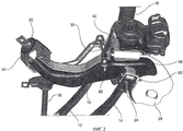
на фиг.1 и 2 показан изометрический вид сверху и снизу соответственно независимой подвески автотранспортного средства согласно предпочтительному варианту осуществления изобретения;1 and 2 show an isometric view from above and below, respectively, of an independent suspension of a motor vehicle according to a preferred embodiment of the invention;
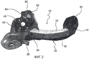
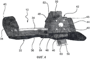
на фиг.3 и 4 показаны изометрические виды изнутри и снаружи соответственно со ссылкой на поперечное направление автотранспортного средства продольного рычага подвески, показанной на фиг.1 и 2; иfigure 3 and 4 shows isometric views from the inside and outside, respectively, with reference to the transverse direction of the vehicle of the trailing arm of the suspension shown in figures 1 and 2; and
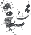
на фиг.5 показан изометрический вид деталей разобранного продольного рычага, показанного на фиг.3 и 4.figure 5 shows an isometric view of the parts of the disassembled trailing arm, shown in figure 3 and 4.
В описании и формуле изобретения, которые следуют ниже, такие термины как «продольный» и «поперечный», «внутренний» и «внешний», «передний» и «задний», «верхний» и «нижний» и т.д. следует считать относящимися к собранной подвеске автотранспортного средства.In the description and claims that follow, such terms as “longitudinal” and “transverse”, “internal” and “external”, “front” and “rear”, “upper” and “lower”, etc. should be considered relevant to the assembled vehicle suspension.
Как показано на фиг.1 и 2, задняя независимая подвеска автотранспортного средства содержит хорошо известный продольный рычаг 10, шарнирно присоединенный на своем переднем конце к каркасу транспортного средства и несет на своем заднем участке соответствующее заднее колесо транспортного средства (не показано), пару тяг 12 и 14, каждая из которых соединяет рычаг 10 с каркасом транспортного средства, пружину (не показано) и амортизатор 16, каждый из которых установлен между рычагом 10 и каркасом транспортного средства, и торсион 18, соединяющий показанный продольный рычаг 10 с идентичным продольным рычагом, связанным с другим колесом транспортного средства.As shown in figures 1 and 2, the rear independent suspension of the vehicle contains a well-known
Продольный рычаг 10 шарнирно присоединен к каркасу транспортного средства посредством вкладыша 20, который в показанном варианте осуществления сориентирован наискосок к оси заднего колеса. Продольный рычаг 10 выполнен с возможностью контроля трех степеней свободы колеса.The
Верхняя соединительная тяга 12 шарнирно присоединена на первом конце к продольному рычагу 10 посредством вкладыша 22. Нижняя соединительная тяга 14 шарнирно присоединена на первом конце к продольному рычагу 10 посредством вкладыша 24. Две продольные соединительные тяги 12 и 14 контролируют каждая по одной степени свободы колеса.The upper connecting rod 12 is pivotally connected at the first end to the
Амортизатор 16 шарнирно присоединен на нижнем конце напрямую к продольному рычагу 10 посредством пальца 26, тогда как пружина покоится своим нижним концом на пластине 28 продольного рычага 10.The
Торсион 18 соединен на каждом из своих боковых концов с соответствующим продольным рычагом 10 посредством соединительного стержня 30 (фиг.2).A
Конструкция продольного рычага 10 будет более подробно описана со ссылками на фиг.3-5.The design of the
Продольный рычаг 10 содержит установочную несущую конструкцию 32 балочного типа. В показанном варианте осуществления установочная несущая конструкция 32 имеет замкнутое поперечное сечение и образована верхней частью 34 из листового металла и нижней частью 36 из листового металла, которые имеют U-образное сечение и прочно соединены между собой.The
Ряд компонентов, отдельных друг от друга, и имеющих каждый конкретную функцию, а именно функцию соединения продольного рычага 10 с каркасом транспортного средства, функцию соединения тяг 12 и 14 с продольным рычагом 10, функцию соединения амортизатора 16 с продольным рычагом 10, функцию несения пружины, функцию соединения торсиона 18 с продольным рычагом 10 и функцию крепления оси вращения колеса, прикреплены к установочной несущей конструкции 32. Обычно все эти компоненты являются штампованными деталями из листовой стали.A number of components that are separate from each other, and having each specific function, namely, the function of connecting the
Функцию соединения продольного рычага 10 с каркасом транспортного средства выполняет деталь 38, например деталь из листовой стали, прочно закрепленная на передней части установочной несущей конструкции 32 и несущая цилиндрическое посадочное гнездо 40 для шарнирного вкладыша 20.The function of connecting the
Функцию соединения верхней тяги 12 с продольным рычагом 10 и несения оси вращения колеса выполняет деталь 42, например деталь из листового металла, образующая вертикальную стенку 44, снабженную центральным отверстием 46 и рядом (обычно четыре) отверстий 48, расположенных вокруг центрального отверстия 46 для установки крепежных винтов (не показано), и верхним участком 50 прикрепления для прикрепления вкладыша 22, в указанном участке создано отверстие 52 для соответствующего шарнирного пальца (не показано). Второе отверстие 54, расположенное на одной оси с отверстием 52, создано в дополнительной детали 56, например детали из листового металла, прочно соединенной с верхним участком 50 прикрепления.The function of connecting the upper link 12 with the
Функцию соединения нижней тяги 14 с продольным рычагом 10 выполняет деталь 58 в виде скобы, например деталь из листового металла, которая имеет два расположенных на одной оси отверстия 60 для шарнирного пальца 62 (фиг.2) вкладыша 24.The function of connecting the
Функцию соединения амортизатора 16 с продольным рычагом 10 выполняет втулка 64, выполненная в показанном примере в виде полого цилиндрического элемента и закрепленная на верхней листовой металлической части 34 установочной несущей конструкции 32. Вышеупомянутый шарнирный палец 26 вставляется во втулку 64.The function of connecting the shock absorber 16 with the
Функцию несения пружины выполняет вышеупомянутая пластина 28.The spring bearing function is performed by the
В заключение, функцию соединения торсиона 18, или скорее соединение тяги 30, с продольным рычагом 10 выполняет деталь 66 из листового металла (фиг.2), прочно закрепленная на установочной несущей конструкции 32 продольного рычага 10.In conclusion, the function of connecting the
Как можно понять из предшествующего описания, продольный рычаг согласно изобретению отличается тем, что содержит множество отдельных компонентов, выполненных, например, как штампованные детали из листового металла, предназначенных для выполнения конкретной функции. Продольный рычаг, таким образом, имеет модульную конструкцию, создающую функциональное разделение, то есть возможность изменения типа и/или геометрического строения отдельных функциональных компонентов без необходимости изменения остальных деталей рычага. При остающемся неизменным геометрическом строении установочной несущей конструкции продольного рычага все функциональные компоненты можно фактически менять независимо друг от друга, для удовлетворения требований, диктуемых каждый раз определенными вариантами практического применения. Таким образом, является возможным изготовление продольных рычагов, спроектированных для транспортных средств, принадлежащих к различным весовым категориям и классам использования посредством адаптирования всегда одной установочной несущей конструкции. Это позволяет достигнуть значительных преимуществ в затратах и технологическом процессе.As can be understood from the foregoing description, the trailing arm according to the invention is characterized in that it comprises a plurality of individual components, such as stamped sheet metal parts, intended to perform a specific function. The longitudinal arm, thus, has a modular design that creates a functional separation, that is, the ability to change the type and / or geometric structure of the individual functional components without the need to change the remaining parts of the lever. With the geometric structure of the mounting support structure of the longitudinal arm remaining unchanged, all functional components can actually be changed independently of each other, in order to satisfy the requirements dictated each time by certain practical applications. Thus, it is possible to produce trailing arms designed for vehicles belonging to different weight categories and classes of use by always adapting a single mounting support structure. This allows for significant cost and process benefits.
Естественно, при остающемся неизменным принципе изобретения варианты осуществления и детали конструкции могут значительно изменяться относительно всего описанного и показанного исключительно в качестве неограничивающего примера.Naturally, with the principle of the invention remaining unchanged, the embodiments and details of the construction can vary significantly with respect to everything described and shown solely as non-limiting example.
Например, амортизатор 16 может образовывать вместе с пружиной пружинно-амортизационный блок, опирающийся на пластину 28. Альтернативно, амортизатор 16 может быть соединен с любым компонентом подвески или опираться на него вместо продольного рычага 10.For example, the
Пружина может также опираться на любой компонент подвески вместо продольного рычага 10. В этом случае пластину 28 определенно можно исключить.The spring can also be supported by any suspension component instead of the
По меньшей мере, возможно также создание другой тяги для соединения продольного рычага 10 с каркасом транспортного средства. В этом случае продольный рычаг 10 мог бы включать в себя дополнительный специальный компонент, например компонент из листового металла, для выполнения функции соединения продольного рычага 10 с этой дополнительной тягой.At the very least, it is also possible to create another traction for connecting the
Также торсион 18 можно соединить с другим компонентом подвески вместо продольного рычага 10, результатом чего будет удаление детали 66, предназначенной для выполнения функции прикрепления торсиона.Also, the
Более того, установочная конструкция 32 продольного рычага может также иметь замкнутое сечение формы, отличающейся от показанной, или иметь открытое сечение.Moreover, the
В заключение, опорная конструкция и/или другие компоненты или детали продольного рычага 10 могут быть изготовлены не только из листового металла (стали или алюминия или других металлов), но также могут быть изготовлены из пластмассового материала, армированного стекловолокном или углеродным волокном, или литого металла, или опять же могут быть образованы из компонентов, полученных экструзионным прессованием.In conclusion, the support structure and / or other components or details of the trailing
Claims (8)
продольный рычаг (10) для шарнирного соединения на своем переднем конце с каркасом транспортного средства и несения на своем заднем участке соответствующего заднего колеса транспортного средства,
первую тягу (12) и вторую тягу (14), каждая из которых соединяет продольный рычаг (10) с каркасом транспортного средства и выполнена с возможностью контроля одной степени свободы колеса,
при этом продольный рычаг (10) содержит установочную несущую конструкцию (32) балочного типа и множество компонентов, отдельных друг от друга и прочно соединенных, напрямую или ненапрямую, с установочной несущей конструкцией (32) для выполнения каждым конкретной функции, причем упомянутое множество компонентов включает в себя первый компонент (38, 40) для установки первого вкладыша (20) для шарнирного соединения продольного рычага (10) с каркасом транспортного средства, и второй компонент (42) для несения оси вращения колеса,
отличающаяся тем, что продольный рычаг (10) выполнен с возможностью контроля трех степеней свободы колеса и упомянутое множество компонентов дополнительно включает в себя третий компонент (50, 56) для установки второго вкладыша (22) для шарнирного соединения продольного рычага (10) с первой тягой (12), и четвертый компонент (58) для установки третьего вкладыша (24) для шарнирного соединения продольного рычага (10) со второй тягой (14).1. The rear independent suspension for a vehicle containing
a longitudinal arm (10) for articulating at its front end with the vehicle frame and bearing at its rear portion a corresponding rear wheel of the vehicle,
the first link (12) and the second link (14), each of which connects the trailing arm (10) to the vehicle frame and is configured to control one degree of freedom of the wheel,
wherein the longitudinal arm (10) comprises an installation supporting structure (32) of a beam type and a plurality of components that are separate from each other and firmly connected, directly or indirectly, with the installation supporting structure (32) for each specific function, and the aforementioned many components include the first component (38, 40) for mounting the first liner (20) for articulating the trailing arm (10) with the vehicle frame, and the second component (42) for supporting the axis of rotation of the wheel,
characterized in that the longitudinal arm (10) is configured to control three degrees of freedom of the wheel and the aforementioned set of components further includes a third component (50, 56) for mounting a second liner (22) for articulating the longitudinal arm (10) with the first link (12), and the fourth component (58) for installing the third liner (24) for articulating the longitudinal arm (10) with the second rod (14).
Applications Claiming Priority (2)
| Application Number | Priority Date | Filing Date | Title |
|---|---|---|---|
| IT000572A ITTO20060572A1 (en) | 2006-08-01 | 2006-08-01 | LONGITUDINAL ARM FOR A REAR SUSPENSION WITH INDEPENDENT WHEELS FOR MOTOR VEHICLES |
| IT??2006?000572 | 2006-08-01 |
Publications (2)
| Publication Number | Publication Date |
|---|---|
| RU2009107150A RU2009107150A (en) | 2010-09-10 |
| RU2425762C2 true RU2425762C2 (en) | 2011-08-10 |
Family
ID=38899522
Family Applications (1)
| Application Number | Title | Priority Date | Filing Date |
|---|---|---|---|
| RU2009107150/11A RU2425762C2 (en) | 2006-08-01 | 2007-07-31 | Lengthwise lever for automotive rear independent suspension |
Country Status (8)
| Country | Link |
|---|---|
| US (1) | US8020882B2 (en) |
| EP (1) | EP2073990B1 (en) |
| AT (1) | ATE501872T1 (en) |
| BR (1) | BRPI0714076B1 (en) |
| DE (1) | DE602007013262D1 (en) |
| IT (1) | ITTO20060572A1 (en) |
| RU (1) | RU2425762C2 (en) |
| WO (1) | WO2008015636A2 (en) |
Families Citing this family (10)
| Publication number | Priority date | Publication date | Assignee | Title |
|---|---|---|---|---|
| KR100941255B1 (en) * | 2007-10-05 | 2010-02-11 | 현대자동차주식회사 | Trailing arm mounting device for small frame vehicles |
| DE102008013155A1 (en) * | 2008-03-07 | 2009-09-10 | Audi Ag | Adjustable wheel carrier |
| KR101180942B1 (en) * | 2009-12-04 | 2012-09-07 | 현대자동차주식회사 | Suspension arm |
| DE102012021289B4 (en) * | 2012-10-30 | 2023-05-04 | Volkswagen Ag | Vehicle axle for a motor vehicle and motor vehicle with such a vehicle axle |
| DE102014011859A1 (en) * | 2014-08-09 | 2016-02-11 | Man Truck & Bus Ag | Axle suspension for steered rigid axles in vehicles, in particular in commercial vehicles |
| DE102014011861A1 (en) * | 2014-08-09 | 2016-02-11 | Man Truck & Bus Ag | Four-point link |
| DE102016210074B4 (en) * | 2016-06-08 | 2025-07-10 | Ford Global Technologies, Llc | Method for producing a trailing arm for a wheel suspension unit of a motor vehicle |
| DE102017129530A1 (en) * | 2017-01-10 | 2018-07-12 | Ksm Castings Group Gmbh | Handlebar for a multi-link axle of a motor vehicle |
| EP3456557B1 (en) | 2017-09-13 | 2020-05-06 | C.R.F. Società Consortile per Azioni | Oscillating arm of a motor-vehicle suspension |
| JP6717445B1 (en) * | 2018-12-26 | 2020-07-01 | 日本製鉄株式会社 | Car undercarriage parts |
Citations (5)
| Publication number | Priority date | Publication date | Assignee | Title |
|---|---|---|---|---|
| FR1353915A (en) * | 1962-04-18 | 1964-02-28 | Ferguson Res Ltd Harry | Advanced rear suspension mechanism for motor vehicles |
| EP0302226A2 (en) * | 1983-09-02 | 1989-02-08 | Mazda Motor Corporation | Vehicle rear suspension system |
| SU1710362A1 (en) * | 1990-02-14 | 1992-02-07 | Efremov Yurij N | Independent wheel suspension |
| DE4129643A1 (en) * | 1991-09-06 | 1993-03-18 | Bayerische Motoren Werke Ag | Independent suspension for non-steered vehicle wheel - has radial main axis running in direction of interference forces of inclined telescopic strut whose lower end is connected to linkage arm |
| EP1216858A2 (en) * | 2000-12-19 | 2002-06-26 | Mazda Motor Corporation | Motor vehicle suspension system |
Family Cites Families (11)
| Publication number | Priority date | Publication date | Assignee | Title |
|---|---|---|---|---|
| US3193302A (en) * | 1962-04-18 | 1965-07-06 | Harry Fergnson Res Ltd | Rear suspension mechanism for motor vehicles |
| FR1425504A (en) * | 1964-12-10 | 1966-01-24 | Publicite Francaise | Vehicle rear suspension |
| DE3434790A1 (en) | 1983-09-22 | 1985-04-18 | Honda Giken Kogyo K.K., Tokio/Tokyo | REAR SUSPENSION FOR A MOTOR VEHICLE |
| US4618159A (en) | 1984-11-13 | 1986-10-21 | The Budd Company | Steering knuckle assembly |
| DE3703196A1 (en) | 1987-02-03 | 1988-08-11 | Bayerische Motoren Werke Ag | WHEEL SUSPENSION FOR STEERING REAR WHEELS OF VEHICLES EQUIPPED WITH FRONT WHEEL STEERING, IN PARTICULAR PERSONAL VEHICLES |
| IT1212163B (en) * | 1987-12-30 | 1989-11-08 | Fiat Auto Spa | REAR SUSPENSION FOR VEHICLES OF THE TYPE WITH INDEPENDENT WHEELS AND LONGITUDINAL ARMS |
| JPH0253620A (en) | 1988-08-16 | 1990-02-22 | Mitsubishi Motors Corp | Rear suspension of vehicle |
| JP3165944B2 (en) | 1994-07-21 | 2001-05-14 | ダイハツ工業株式会社 | Independent suspension |
| US6138357A (en) * | 1997-12-08 | 2000-10-31 | Ford Global Technologies, Inc. | Method of making knuckle assembly |
| FR2832099B1 (en) | 2001-11-09 | 2004-07-02 | Peugeot Citroen Automobiles Sa | REAR AXLE WITH MULTI-ARM AXLE AND PIN SPRING |
| WO2007024919A2 (en) | 2005-08-23 | 2007-03-01 | Zf Lemforder Corporation | Knuckle-trailing blade assembly |
-
2006
- 2006-08-01 IT IT000572A patent/ITTO20060572A1/en unknown
-
2007
- 2007-07-31 DE DE602007013262T patent/DE602007013262D1/en active Active
- 2007-07-31 WO PCT/IB2007/053015 patent/WO2008015636A2/en not_active Ceased
- 2007-07-31 RU RU2009107150/11A patent/RU2425762C2/en not_active IP Right Cessation
- 2007-07-31 US US12/375,604 patent/US8020882B2/en not_active Expired - Fee Related
- 2007-07-31 AT AT07825974T patent/ATE501872T1/en not_active IP Right Cessation
- 2007-07-31 BR BRPI0714076-2A patent/BRPI0714076B1/en not_active IP Right Cessation
- 2007-07-31 EP EP07825974A patent/EP2073990B1/en not_active Not-in-force
Patent Citations (5)
| Publication number | Priority date | Publication date | Assignee | Title |
|---|---|---|---|---|
| FR1353915A (en) * | 1962-04-18 | 1964-02-28 | Ferguson Res Ltd Harry | Advanced rear suspension mechanism for motor vehicles |
| EP0302226A2 (en) * | 1983-09-02 | 1989-02-08 | Mazda Motor Corporation | Vehicle rear suspension system |
| SU1710362A1 (en) * | 1990-02-14 | 1992-02-07 | Efremov Yurij N | Independent wheel suspension |
| DE4129643A1 (en) * | 1991-09-06 | 1993-03-18 | Bayerische Motoren Werke Ag | Independent suspension for non-steered vehicle wheel - has radial main axis running in direction of interference forces of inclined telescopic strut whose lower end is connected to linkage arm |
| EP1216858A2 (en) * | 2000-12-19 | 2002-06-26 | Mazda Motor Corporation | Motor vehicle suspension system |
Also Published As
| Publication number | Publication date |
|---|---|
| WO2008015636A3 (en) | 2008-09-25 |
| ITTO20060572A1 (en) | 2008-02-02 |
| US20090315291A1 (en) | 2009-12-24 |
| BRPI0714076B1 (en) | 2019-06-18 |
| BRPI0714076A2 (en) | 2012-12-18 |
| BRPI0714076A8 (en) | 2015-09-08 |
| WO2008015636A2 (en) | 2008-02-07 |
| EP2073990A2 (en) | 2009-07-01 |
| DE602007013262D1 (en) | 2011-04-28 |
| US8020882B2 (en) | 2011-09-20 |
| EP2073990B1 (en) | 2011-03-16 |
| ATE501872T1 (en) | 2011-04-15 |
| RU2009107150A (en) | 2010-09-10 |
Similar Documents
| Publication | Publication Date | Title |
|---|---|---|
| RU2425762C2 (en) | Lengthwise lever for automotive rear independent suspension | |
| US5536035A (en) | Dual suspension shock tower | |
| KR102144411B1 (en) | Subframe for a motor vehicle | |
| CN104837715B (en) | Body structure | |
| JP7767045B2 (en) | Integrated rear lower and body frame | |
| CN107685776B (en) | Body structure for dual-rut vehicles | |
| JP2010522667A (en) | Suspension device of the leading or trailing arm type with a fully integrated arm | |
| CN101186223A (en) | Shock strut support | |
| AU772129B2 (en) | Steering gear frame | |
| JPH05193520A (en) | Subframe for automobile | |
| KR101450755B1 (en) | Mounting bracket for suspension of automotive | |
| CN106335334A (en) | Motor Vehicle Wheel Suspension | |
| KR20040022749A (en) | Front whell suspension system using steering gear frame | |
| US8616568B2 (en) | Structure of vehicle subframe | |
| CA2363289A1 (en) | Vehicle antisway bar | |
| JP3092617B1 (en) | Automotive suspension mounting structure | |
| KR20030089716A (en) | Shock absorber module | |
| KR100911406B1 (en) | Subframe for the front suspension of the vehicle | |
| KR100737028B1 (en) | Lower arm mounting structure for vehicle suspension | |
| JP2006502897A (en) | Structure for mounting spring and / or cushioning element to hollow support of automobile body | |
| CN107264218A (en) | Axle suspension system system with QS and the vehicle with axle suspension system system | |
| EP1578655B1 (en) | Stabilizer | |
| US20040227320A1 (en) | Independent front suspension engine attachment | |
| JP2000108935A (en) | Car front body structure | |
| JPH10181636A (en) | Radiator fitting mechanism for vehicle |
Legal Events
| Date | Code | Title | Description |
|---|---|---|---|
| MM4A | The patent is invalid due to non-payment of fees |
Effective date: 20200801 |