RU2425656C2 - Method of manufacturing tubular medical implant - Google Patents
Method of manufacturing tubular medical implant Download PDFInfo
- Publication number
- RU2425656C2 RU2425656C2 RU2006141499/14A RU2006141499A RU2425656C2 RU 2425656 C2 RU2425656 C2 RU 2425656C2 RU 2006141499/14 A RU2006141499/14 A RU 2006141499/14A RU 2006141499 A RU2006141499 A RU 2006141499A RU 2425656 C2 RU2425656 C2 RU 2425656C2
- Authority
- RU
- Russia
- Prior art keywords
- thread
- needle
- implant
- bobbin
- shuttle
- Prior art date
Links
- 239000007943 implant Substances 0.000 title claims abstract description 70
- 238000004519 manufacturing process Methods 0.000 title description 8
- 238000000034 method Methods 0.000 claims abstract description 31
- 238000009958 sewing Methods 0.000 claims abstract description 8
- 230000007246 mechanism Effects 0.000 claims description 7
- 230000015572 biosynthetic process Effects 0.000 abstract description 11
- 230000006872 improvement Effects 0.000 abstract description 2
- 239000003814 drug Substances 0.000 abstract 2
- 238000010276 construction Methods 0.000 abstract 1
- 239000000126 substance Substances 0.000 abstract 1
- 230000003014 reinforcing effect Effects 0.000 description 15
- 239000000758 substrate Substances 0.000 description 9
- 239000002184 metal Substances 0.000 description 5
- 230000009471 action Effects 0.000 description 4
- 239000000463 material Substances 0.000 description 4
- 230000008569 process Effects 0.000 description 4
- 238000013459 approach Methods 0.000 description 2
- 239000004744 fabric Substances 0.000 description 2
- 230000002401 inhibitory effect Effects 0.000 description 2
- 230000036961 partial effect Effects 0.000 description 2
- 229920001343 polytetrafluoroethylene Polymers 0.000 description 2
- 239000004810 polytetrafluoroethylene Substances 0.000 description 2
- 239000004753 textile Substances 0.000 description 2
- 230000008901 benefit Effects 0.000 description 1
- 239000008280 blood Substances 0.000 description 1
- 210000004369 blood Anatomy 0.000 description 1
- 210000004204 blood vessel Anatomy 0.000 description 1
- 230000008859 change Effects 0.000 description 1
- 230000005484 gravity Effects 0.000 description 1
- 230000036541 health Effects 0.000 description 1
- 210000003709 heart valve Anatomy 0.000 description 1
- 230000001788 irregular Effects 0.000 description 1
- 238000003698 laser cutting Methods 0.000 description 1
- 230000000670 limiting effect Effects 0.000 description 1
- 239000012528 membrane Substances 0.000 description 1
- 239000007769 metal material Substances 0.000 description 1
- 210000000056 organ Anatomy 0.000 description 1
- 229920000728 polyester Polymers 0.000 description 1
- -1 polytetrafluoroethylene Polymers 0.000 description 1
- 235000020004 porter Nutrition 0.000 description 1
- 230000002829 reductive effect Effects 0.000 description 1
- 239000011819 refractory material Substances 0.000 description 1
- 230000001105 regulatory effect Effects 0.000 description 1
- 239000007787 solid Substances 0.000 description 1
- 239000003356 suture material Substances 0.000 description 1
- 210000002073 venous valve Anatomy 0.000 description 1
- 238000004804 winding Methods 0.000 description 1
Images
Classifications
-
- A—HUMAN NECESSITIES
- A61—MEDICAL OR VETERINARY SCIENCE; HYGIENE
- A61F—FILTERS IMPLANTABLE INTO BLOOD VESSELS; PROSTHESES; DEVICES PROVIDING PATENCY TO, OR PREVENTING COLLAPSING OF, TUBULAR STRUCTURES OF THE BODY, e.g. STENTS; ORTHOPAEDIC, NURSING OR CONTRACEPTIVE DEVICES; FOMENTATION; TREATMENT OR PROTECTION OF EYES OR EARS; BANDAGES, DRESSINGS OR ABSORBENT PADS; FIRST-AID KITS
- A61F2/00—Filters implantable into blood vessels; Prostheses, i.e. artificial substitutes or replacements for parts of the body; Appliances for connecting them with the body; Devices providing patency to, or preventing collapsing of, tubular structures of the body, e.g. stents
- A61F2/95—Instruments specially adapted for placement or removal of stents or stent-grafts
-
- D—TEXTILES; PAPER
- D05—SEWING; EMBROIDERING; TUFTING
- D05B—SEWING
- D05B23/00—Sewing apparatus or machines not otherwise provided for
-
- A—HUMAN NECESSITIES
- A61—MEDICAL OR VETERINARY SCIENCE; HYGIENE
- A61F—FILTERS IMPLANTABLE INTO BLOOD VESSELS; PROSTHESES; DEVICES PROVIDING PATENCY TO, OR PREVENTING COLLAPSING OF, TUBULAR STRUCTURES OF THE BODY, e.g. STENTS; ORTHOPAEDIC, NURSING OR CONTRACEPTIVE DEVICES; FOMENTATION; TREATMENT OR PROTECTION OF EYES OR EARS; BANDAGES, DRESSINGS OR ABSORBENT PADS; FIRST-AID KITS
- A61F2/00—Filters implantable into blood vessels; Prostheses, i.e. artificial substitutes or replacements for parts of the body; Appliances for connecting them with the body; Devices providing patency to, or preventing collapsing of, tubular structures of the body, e.g. stents
- A61F2/02—Prostheses implantable into the body
- A61F2/04—Hollow or tubular parts of organs, e.g. bladders, tracheae, bronchi or bile ducts
- A61F2/06—Blood vessels
-
- A—HUMAN NECESSITIES
- A61—MEDICAL OR VETERINARY SCIENCE; HYGIENE
- A61F—FILTERS IMPLANTABLE INTO BLOOD VESSELS; PROSTHESES; DEVICES PROVIDING PATENCY TO, OR PREVENTING COLLAPSING OF, TUBULAR STRUCTURES OF THE BODY, e.g. STENTS; ORTHOPAEDIC, NURSING OR CONTRACEPTIVE DEVICES; FOMENTATION; TREATMENT OR PROTECTION OF EYES OR EARS; BANDAGES, DRESSINGS OR ABSORBENT PADS; FIRST-AID KITS
- A61F2/00—Filters implantable into blood vessels; Prostheses, i.e. artificial substitutes or replacements for parts of the body; Appliances for connecting them with the body; Devices providing patency to, or preventing collapsing of, tubular structures of the body, e.g. stents
- A61F2/82—Devices providing patency to, or preventing collapsing of, tubular structures of the body, e.g. stents
- A61F2/86—Stents in a form characterised by the wire-like elements; Stents in the form characterised by a net-like or mesh-like structure
-
- D—TEXTILES; PAPER
- D05—SEWING; EMBROIDERING; TUFTING
- D05B—SEWING
- D05B57/00—Loop takers, e.g. loopers
- D05B57/08—Loop takers, e.g. loopers for lock-stitch sewing machines
- D05B57/10—Shuttles
- D05B57/12—Shuttles oscillating
-
- A—HUMAN NECESSITIES
- A61—MEDICAL OR VETERINARY SCIENCE; HYGIENE
- A61F—FILTERS IMPLANTABLE INTO BLOOD VESSELS; PROSTHESES; DEVICES PROVIDING PATENCY TO, OR PREVENTING COLLAPSING OF, TUBULAR STRUCTURES OF THE BODY, e.g. STENTS; ORTHOPAEDIC, NURSING OR CONTRACEPTIVE DEVICES; FOMENTATION; TREATMENT OR PROTECTION OF EYES OR EARS; BANDAGES, DRESSINGS OR ABSORBENT PADS; FIRST-AID KITS
- A61F2/00—Filters implantable into blood vessels; Prostheses, i.e. artificial substitutes or replacements for parts of the body; Appliances for connecting them with the body; Devices providing patency to, or preventing collapsing of, tubular structures of the body, e.g. stents
- A61F2/02—Prostheses implantable into the body
- A61F2/04—Hollow or tubular parts of organs, e.g. bladders, tracheae, bronchi or bile ducts
- A61F2/06—Blood vessels
- A61F2/07—Stent-grafts
- A61F2002/075—Stent-grafts the stent being loosely attached to the graft material, e.g. by stitching
Landscapes
- Health & Medical Sciences (AREA)
- Engineering & Computer Science (AREA)
- Biomedical Technology (AREA)
- Textile Engineering (AREA)
- Life Sciences & Earth Sciences (AREA)
- Public Health (AREA)
- Heart & Thoracic Surgery (AREA)
- Vascular Medicine (AREA)
- Oral & Maxillofacial Surgery (AREA)
- Animal Behavior & Ethology (AREA)
- General Health & Medical Sciences (AREA)
- Transplantation (AREA)
- Veterinary Medicine (AREA)
- Cardiology (AREA)
- Gastroenterology & Hepatology (AREA)
- Pulmonology (AREA)
- Prostheses (AREA)
- Sewing Machines And Sewing (AREA)
- Media Introduction/Drainage Providing Device (AREA)
Abstract
Description
Настоящее изобретения относится к способу изготовления трубчатого медицинского имплантата и сшивному устройству, которые могут быть использованы для изготовления различных трубчатых медицинских форм, в частности трансплантат-стент, трансплантат.The present invention relates to a method for manufacturing a tubular medical implant and a stapling device that can be used to produce various tubular medical forms, in particular a stent transplant, a transplant.
Трансплантаты-стенты представляют собой трубчатые конструкции, которые применяют внутри кровеносных сосудов. Обычно они состоят из двух элементов: трубки, почти непроницаемой для крови, которая обычно выполнена из текстильного или перепончатого материала, и армирующей структуры, обычно выполненной из проволоки или иного нитевидного металлического материала.Stent transplants are tubular structures that are used inside blood vessels. Usually they consist of two elements: a tube that is almost impervious to blood, which is usually made of textile or webbed material, and a reinforcing structure, usually made of wire or other filamentary metal material.
Трубчатый элемент конструкции трансплантата обычно состоит из тканого полиэфирного материала, однако, в ряде моделей используют мембраны из политетрафторэтилена (ПТФЭ). Трансплантат опирается на металлические кольца, обычно выполненные из проволоки, но изредка вырезанные из металлической трубки методом лазерной резки или аналогичным способом. Прикрепленные к трансплантату металлические кольца образуют общую плоскость, расположенную под определенным углом к трансплантату. Кольца могут иметь волнистую форму, ограничивая поверхность короткого цилиндра на поверхности трансплантата, либо имеют отверстия или соединены, образуя длинный цилиндрический армирующий элемент на поверхности трансплантата.The tubular element of the transplant design usually consists of a woven polyester material, however, in some models polytetrafluoroethylene (PTFE) membranes are used. The transplant rests on metal rings, usually made of wire, but occasionally cut out of a metal tube by laser cutting or a similar method. The metal rings attached to the graft form a common plane located at a certain angle to the graft. The rings can have a wavy shape, limiting the surface of a short cylinder on the surface of the graft, or have holes or are connected to form a long cylindrical reinforcing element on the surface of the graft.
Почти во всех конструкциях армирующие кольца прикрепляют к поверхности трансплантата, пришивая их, главным образом, вручную. В некоторых конструкциях используют сотни или тысячи швов, что удорожает такую конструкцию. Кроме того, чтобы обеспечить качество каждого шва, требуются значительные затраты, а вероятность низкого качества швов в устройстве, которое имплантируют пациенту, может создать серьезную угрозу его здоровью.In almost all designs, reinforcing rings are attached to the surface of the graft, sewing them mainly by hand. In some designs, hundreds or thousands of seams are used, which makes such a design more expensive. In addition, to ensure the quality of each suture, significant costs are required, and the likelihood of poor quality sutures in the device that is implanted into the patient can pose a serious threat to his health.
Также необходимо, чтобы трансплантаты-стенты изготавливались в соответствии с индивидуальными анатомическими особенностями пациентов. В частности, такие параметры трансплантатов-стентов, как их длина, диаметр, конусообразность, дополнительная конусообразность и расположение боковых ответвлений должны определяться индивидуально для каждого пациента, что может чрезмерно удлинить процесс изготовления трансплантатов-стентов вручную.It is also necessary that the stent transplants are made in accordance with the individual anatomical features of the patients. In particular, such parameters of stent grafts as their length, diameter, cone shape, additional cone shape and location of lateral branches should be determined individually for each patient, which can excessively lengthen the manufacturing process of stent grafts manually.
В заявке WO 99/37242 (на имя заявителя настоящей заявки) предложено альтернативное решение, согласно которому для изготовления плоского приспособления, которому затем придают трубчатую форму, используют компьютеризованное сшивание. Благодаря такому подходу решаются многие проблемы, осложняющие ручное изготовление, однако, при этом появляется шов и становится невозможным изготавливать сплошные конструкции.WO 99/37242 (in the name of the applicant of this application) proposes an alternative solution according to which computerized stitching is used to make a flat device, which is then tubular. Thanks to this approach, many problems that complicate manual manufacturing are solved, however, at the same time, a seam appears and it becomes impossible to produce solid structures.
В Британском патенте 2165559 (University College London) описано сшивное устройство для прошивания субстрата, например, одной из тканей организма в процессе хирургического оперативного вмешательства. Для того чтобы согнутый отрезок субстрата оказался между иглой и челноком, его всасывают в сшивное устройство. После этого с помощью иглы нить пропускают через согнутый отрезок субстрата таким образом, чтобы показался другой ее конец, и зацепляют нить за челнок. Сшивное устройство перемещается вдоль субстрата и многократно осуществляет данную операцию, за счет чего субстрат оказывается прошит. Такое сшивное устройство не может применяться для прошивания нитью стенки трубчатого трансплантата, поскольку трансплантат не является достаточно эластичным для того, чтобы его согнутый отрезок мог быть втянут в сшивное устройство.British Patent 2165559 (University College London) describes a stitching device for flashing a substrate, for example, one of the body tissues during a surgical operation. In order for the bent segment of the substrate to be between the needle and the shuttle, it is sucked into the stapler. After that, with the help of a needle, the thread is passed through a bent segment of the substrate so that its other end appears, and the thread is hooked onto the shuttle. The stitching device moves along the substrate and repeatedly performs this operation, due to which the substrate is stitched. Such a stitching device cannot be used for flashing the wall of a tubular graft, since the graft is not elastic enough so that its bent length can be pulled into the stitching device.
В патенте США 4502159 (Shiley Incorporated) описан способ формирования трубчатого протеза, согласно которому ткань перикарда свертывают в трубку и прошивают вдоль, в результате чего образуется продольный шов. Тем не менее ткань прошивают обычным способом, пропуская нить с одной стороны шва на другую, расположенную снаружи трубки.US Pat. No. 4,502,159 (Shiley Incorporated) describes a method for forming a tubular prosthesis, according to which the pericardial tissue is rolled into a tube and stitched along, resulting in a longitudinal seam. Nevertheless, the fabric is stitched in the usual way, passing the thread from one side of the seam to the other, located outside the tube.
В патенте США 4241681 (Porter) описано сшивное устройство для сшивания нескольких армирующих колец, расположенных на определенном расстоянии друг от друга на длинной гибкой трубке из огнеупорного материала. Такое устройство имеет длинную трубчатую опору, на которую заготовку надевают как рукав на руку. Оно также имеет неподвижный сшивающий механизм, прошивающий заготовку однониточным цепным швом, а выталкиватель продвигает заготовку по опоре по мере ее прошивания.US Pat. No. 4,241,681 (Porter) describes a stitching device for stitching several reinforcing rings located at a certain distance from each other on a long flexible tube of refractory material. Such a device has a long tubular support, on which the workpiece is worn as a sleeve on the arm. It also has a fixed stitching mechanism, stitching the workpiece with a single-strand chain seam, and the ejector moves the workpiece along the support as it is stitched.
В патенте США 4414908 (Janome Sewing Machine Co., Limited) описано сшивное устройство для сшивания иссеченных тканей и органов пациента. Устройство имеет держатель иглы (по существу, щипцы-плоскогубцы) и держатель челнока, с возможность скольжения установленный на держателе иглы. При этом игла ни при каких степенях свободы не может перемешаться независимо от челнока. В частности, перемещение держателя иглы с целью проколоть иглой стенку трубчатого имплантата неизбежно приводит к соответствующему перемещению челнока в просвете имплантата. На практике было бы невозможно управлять иглой, избегая воздействия челнока на боковые стенки имплантата. что чревато опасностью повреждения имплантата.US Pat. No. 4,414,908 (Janome Sewing Machine Co., Limited) describes a stapler for stitching excised tissues and organs of a patient. The device has a needle holder (essentially pliers) and a hook holder that slidably mounted on the needle holder. At the same time, the needle cannot be mixed at any degrees of freedom, regardless of the shuttle. In particular, moving the needle holder to pierce the wall of the tubular implant with the needle inevitably leads to a corresponding movement of the shuttle in the lumen of the implant. In practice, it would be impossible to control the needle, avoiding the shuttle impact on the side walls of the implant. which is fraught with the risk of damage to the implant.
В альтернативном варианте осуществления патента США 4414908 челнок установлен на стержне, способном скользить в продольном направлении параллельно оси держателя иглы, а держатель иглы способен вращаться вокруг оси стержня челнока. Это значит, что при вращении держателя иглы игла перемещается по окружности, находясь на равном расстоянии от челнока. Таким образом, игла никогда не смогла бы проникнуть через стенку трубчатого имплантата, а просто перемещалась бы вокруг имплантата на постоянном расстоянии от центра его просвета.In an alternative embodiment of US Pat. No. 4,414,908, the shuttle is mounted on a rod capable of sliding in the longitudinal direction parallel to the axis of the needle holder, and the needle holder is able to rotate around the axis of the shuttle shaft. This means that when the needle holder rotates, the needle moves around the circumference, being at an equal distance from the shuttle. Thus, the needle could never penetrate through the wall of the tubular implant, but simply move around the implant at a constant distance from the center of its lumen.
Настоящее изобретение имеет целью устранить вышеназванные недостатки за счет использования способа и механического сшивного устройства, управляемого компьютером, позволяющих делать швы на поверхности узких трубок и пришивать проволоку или иные конструкции к поверхности трубок. В частности, такие структуры пришивают к внутренней или наружной поверхности трубки.The present invention aims to eliminate the above disadvantages through the use of a method and a mechanical stitching device controlled by a computer, allowing you to make seams on the surface of narrow tubes and sew the wire or other structures to the surface of the tubes. In particular, such structures are sewn to the inner or outer surface of the tube.
Описанное устройство также применимо для изготовления других трубчатых приспособлений, имеющих нитевидные элементы, которые помещают на поверхность трубки в ходе отдельной от формирования самой трубки операции.The described device is also applicable for the manufacture of other tubular devices having threadlike elements that are placed on the surface of the tube during a separate operation from the formation of the tube itself.
Технический результат, достигаемый при использовании заявленных изобретений, состоит в устранении недостатков из уровня техники, заключающихся в пришивании различных конструкций к поверхности трубчатого медицинского имплантата вручную, за счет применения механического сшивного устройства, обеспечивающего повышение производительности способа, улучшения качества и снижения стоимости изготовления имплантата.The technical result achieved by using the claimed inventions consists in eliminating the drawbacks of the prior art, which consists in sewing various designs to the surface of a tubular medical implant manually, through the use of a mechanical stitching device that provides increased productivity of the method, improved quality and reduced manufacturing cost of the implant.
Заявка WO 01/30269 (на имя заявителя настоящей заявки) была опубликована позже даты приоритета настоящей заявки. Она относится к способу и устройству для прошивания нитью стенки трансплантата, например, с целью создания трансплантата-стента. Настоящее изобретения является усовершенствованием названной заявки.Application WO 01/30269 (in the name of the applicant of this application) was published later than the priority date of this application. It relates to a method and apparatus for flashing the graft wall with thread, for example, to create a stent graft. The present invention is an improvement on this application.
Для достижения технического результата предлагается устройство для прошивания нитью поверхности трубчатого медицинского имплантата, включающее опору имплантата, иглу для подачи первой нити через поверхность и далее в просвет имплантата, бобину для второй нити, средство перемещения бобины через открытый конец имплантата в упомянутый просвет с целью формирования шва в сочетании с первой нитью и средство отклонения имплантата относительно направления перемещения имплантата.To achieve a technical result, a device is proposed for flashing the surface of a tubular medical implant, including an implant support, a needle for feeding the first thread through the surface and further into the lumen of the implant, a bobbin for the second thread, means for moving the bobbin through the open end of the implant into the lumen with the aim of forming a suture in combination with the first thread and means for deflecting the implant relative to the direction of movement of the implant.
Игла и бобина предпочтительно расположены таким образом, что их продольные оси лежат в одной плоскости. Предпочтительно, оси проходят под углом 90°.The needle and bobbin are preferably positioned so that their longitudinal axis lie in the same plane. Preferably, the axes extend at an angle of 90 °.
За счет взаимного расположения иглы и бобины для сшивания достаточно более ограниченного пространства, чем в случае использования обычного сшивного устройства, а швы можно делать на стенке трубчатых трансплантатов относительно малого диаметра.Due to the mutual arrangement of the needle and the bobbin for stitching a rather more limited space than in the case of using a conventional stitching device, and the seams can be made on the wall of tubular grafts of relatively small diameter.
В предпочтительном варианте осуществления опора бобины выполнена в виде стержня, имеющего углубление, в котором помещается бобина.In a preferred embodiment, the reel support is made in the form of a rod having a recess in which the reel is placed.
В альтернативном варианте осуществления опора бобины выполнена в виде направляющей, по которой бобина свободно перемещается в просвет и из просвета имплантата. Предпочтительно, направляющая выполнена в виде трубки с прорезью, через которую обеспечивается доступ иглы к бобине.In an alternative embodiment, the support of the reel is made in the form of a guide along which the reel freely moves into the lumen and from the lumen of the implant. Preferably, the guide is made in the form of a tube with a slot through which the needle is accessible to the bobbin.
В особо предпочтительном варианте осуществления изобретения бобина помещается в челноке, который, в свою очередь, помещается в углублении стержня или перемещается вверх и вниз по направляющей.In a particularly preferred embodiment of the invention, the bobbin is placed in the shuttle, which, in turn, is placed in the recess of the rod or moves up and down along the guide.
Предпочтительно, челнок смещен в направлении одной из сторон направляющей, расположенной вблизи траектории иглы, за счет чего в процессе работы челнок располагается таким образом, чтобы захватывать петлю первой нити, при этом смещение таково, что челнок может в достаточной степени перемещаться в направлении, противоположном смещению, за счет чего происходит наматывание второй нити на челнок и ее разматывание с челнока.Preferably, the shuttle is biased in the direction of one of the sides of the guide, located near the path of the needle, whereby during operation the shuttle is positioned so as to capture the loop of the first thread, while the bias is such that the shuttle can sufficiently move in the opposite direction to the bias , due to which there is winding the second thread on the shuttle and its unwinding from the shuttle.
В дополнительном варианте осуществления, по меньшей мере, один конец челнока сужен и необязательно изогнут таким образом, что, если он ориентирован внутри направляющей так, как это описано выше, конец челнока оказывается вблизи конца иглы и центра петли шва.In a further embodiment, at least one end of the hook is narrowed and optionally bent so that if it is oriented inside the guide as described above, the end of the hook is near the end of the needle and the center of the weld loop.
Вариант осуществления, в котором бобина помещается в направляющей, особо предпочтителен в случае трансплантатов малого диаметра (примерно 3-6 мм), а вариант осуществления, в котором бобина помещается в углублении стержня, предпочтителен в случае трансплантатов большего диаметра (примерно 7-40 мм).An embodiment in which the bobbin is placed in the guide is particularly preferred in the case of small diameter transplants (about 3-6 mm), and an embodiment in which the bobbin is placed in the recess of the shaft is preferred in the case of larger diameter transplants (about 7-40 mm) .
В одном из предпочтительных вариантов осуществления на вторую нить воздействуют силой трения, пропуская ее через несколько отверстий в челноке или несущем элементе бобины, при этом чем больше число отверстий, тем сильнее тормозящее действие.In one of the preferred embodiments, the second thread is subjected to friction by passing it through several holes in the shuttle or the bobbin supporting element, the larger the number of holes, the greater the inhibitory effect.
В одном из вариантов осуществления названное устройство дополнительно имеет средство натяжения названной второй нити с целью облегчить формирование швов. Средство натяжения имеет улавливающий элемент, способный перемещаться по направляющей независимо от челнока, и стопор, расположенный на противоположной от улавливающего элемента стороне челнока. В процессе работы по мере выхода из челнока вторая нить проходит между улавливающим элементом и челноком и может быть захвачена между улавливающим элементом и челноком за счет принудительного перемещения улавливающего элемента в направлении челнока до стопора, что позволяет создать натяжение второй нити при формировании шва.In one embodiment, said device further has a means of tensioning said second thread to facilitate the formation of seams. The tensioning means has a catching element that can move along the guide independently of the shuttle, and a stopper located on the side of the shuttle opposite the catching element. In the process of work, as you exit the shuttle, the second thread passes between the catching element and the shuttle and can be caught between the catching element and the shuttle due to the forced movement of the catching element in the direction of the shuttle to the stopper, which allows you to create tension of the second thread during the formation of the seam.
В альтернативном варианте осуществления средство натяжения второй нити выполнено из упругого металла, например в виде плоской пружины, улавливающей нить. Устройство может иметь средство создания дополнительного давления на упругий металл с целью способствовать натяжению нити. Названное средство может выполнять дополнительную функцию перемещения челнока по направляющей. Таким образом, перемещение челнока может быть достигнуто на практике за счет толкателей, которые действуют на челнок с каждого конца направляющей трубки.In an alternative embodiment, the tensioning means of the second thread is made of elastic metal, for example in the form of a flat spring trapping the thread. The device may have a means of creating additional pressure on the elastic metal in order to contribute to the tension of the thread. The named tool can perform an additional function of moving the shuttle along the guide. Thus, the movement of the shuttle can be achieved in practice by pushers that act on the shuttle from each end of the guide tube.
В дополнительном варианте осуществления устройство может иметь установленный на бобине регулируемый тормоз, выполненный в виде винта, действующего на бобину, предпочтительно, через резиновую кольцевую прокладку.In an additional embodiment, the device may have an adjustable brake mounted on the bobbin, made in the form of a screw acting on the bobbin, preferably through a rubber ring gasket.
В еще одном дополнительном варианте осуществления устройство имеет челнок или несущий элемент (опора) бобины, который может представлять собой катаное изделие, чтобы вторая нить проходила по ее поверхности, увеличивая силу трения, воздействующую на вторую нить и тем самым создавая тормозящее действие.In yet another additional embodiment, the device has a shuttle or a supporting element (support) of the bobbin, which may be a rolled product, so that the second thread passes over its surface, increasing the friction force acting on the second thread and thereby creating an inhibitory effect.
В одном из вариантов осуществления описанное устройство формирует двойной закрытый шов при помощи несущего элемента бобины (и механизма), способного проходить в просвет изготавливаемой трубки. В процессе изготовления в имплантат вводят направляющую трубку, которая проходит по всей его длине и выступает с обоих концов. В направляющей трубке имеется прорезь (проходящая по всей ее длине), через которую проходит игла и которая обеспечивает ее доступ к челноку. На конце иглы расположена петля шовного материала (или любой нити), оба свободных конца которой остаются на наружной поверхности имплантата. В идеале направляющая трубка имеет некруглую форму в поперечном сечении, обеспечивающую жесткость, утерянную в результате формирования продольной прорези.In one embodiment, the described device forms a double closed seam using a bobbin supporting element (and mechanism) capable of passing into the lumen of the tube being manufactured. In the manufacturing process, a guide tube is inserted into the implant, which extends along its entire length and protrudes from both ends. In the guide tube there is a slot (passing along its entire length) through which the needle passes and which provides its access to the shuttle. At the end of the needle is a loop of suture material (or any thread), both free ends of which remain on the outer surface of the implant. Ideally, the guide tube is non-circular in cross-section, providing stiffness lost as a result of the formation of a longitudinal slot.
Направляющая трубка может быть выполнена, по меньшей мере, из одной фасонной полосы материала, поддерживающего челнок силой тяжести, силой магнитного поля или иной силой квазипостоянного действия. Помимо первой полосы материала в трубке может быть использована соединенная с ней вторая полоса. Целесообразно, чтобы бобина устанавливалась на челноке, выполненном в виде удлиненного элемента, имеющего на протяжении, по меньшей мере, части длины D-образную форму в поперечном сечении.The guide tube may be made of at least one contoured strip of material supporting the shuttle by gravity, magnetic field, or other force of quasi-constant action. In addition to the first strip of material in the tube, a second strip connected to it can be used. It is advisable that the bobbin is mounted on a shuttle made in the form of an elongated element having, for at least part of the length, a D-shape in cross section.
Челнок преимущественно имеет бобину, расположенную внутри несущего элемента, имеющего форму длинного узкого цилиндра. В идеале поверхность несущего элемента бобины имеет неправильную круглую форму в поперечном сечении, а предпочтительно сплющена и совпадает с соответствующей формой направляющей трубки, за счет чего поддерживается ориентация несущего элемента бобины относительно продольной оси.The shuttle preferably has a bobbin located inside the supporting element, having the form of a long narrow cylinder. Ideally, the surface of the bobbin carrier element has an irregular round cross-sectional shape, and is preferably flattened and coincides with the corresponding shape of the guide tube, thereby maintaining the orientation of the bobbin carrier relative to the longitudinal axis.
Предпочтительно, игла имеет преимущественно прямолинейную форму со скошенным сечением («косой кромкой»), облегчающим образование петли. У челнока также может быть соответствующее скошенное сечение, за счет чего игла и челнок совмещаются и занимают меньшее пространство внутри просвета имплантата, чем в обычном сшивном устройстве.Preferably, the needle has a predominantly rectilinear shape with a beveled section (“oblique edge”) facilitating loop formation. The shuttle can also have a corresponding beveled section, due to which the needle and the shuttle are combined and occupy less space inside the lumen of the implant than in a conventional stapler.
Довольно редко при сшивании имплантатов возникает необходимость, чтобы их структуры крепились друг другу лишь швами. Данная задача решена в заявленном устройстве за счет независимого регулирования натяжения нитей в бобине и игле. Регулирование натяжения нити в бобине описано выше, а натяжение нити в игле регулируют при помощи устройства натяжения с электронным управлением, которое действует независимо от положения иглы.Quite rarely, when stitching implants, it becomes necessary that their structures are attached to each other only with sutures. This problem is solved in the claimed device due to the independent regulation of the tension of the threads in the bobbin and needle. The adjustment of the thread tension in the bobbin is described above, and the thread tension in the needle is controlled by an electronically controlled tension device that operates independently of the position of the needle.
Предпочтительно, чтобы устройство дополнительно имело средство натяжения первой нити, у которого средство натяжения действует независимо от механизма, приводящего в действие иглу.Preferably, the device further has a first thread tension means, in which the tension means is independent of the mechanism driving the needle.
На траектории первой нити, второй нити или обеих нитей может находиться датчик деформаций.A strain gauge may be located on the path of the first thread, the second thread, or both threads.
Устройство для изготовления, например, трансплантата-стента должно иметь механизм, фиксирующий трубчатый трансплантат-стент в процессе прошивания его поверхности армирующими швами. Имплантат может иметь участки цилиндрической и конической формы, а изменение диаметра имплантата на протяжении его длины может измеряться различными величинами. Трансплантаты-стенты также могут иметь разветвленную форму.A device for manufacturing, for example, a stent graft should have a mechanism that fixes the tubular stent graft during the flashing of its surface with reinforcing seams. The implant may have sections of cylindrical and conical shape, and a change in the diameter of the implant over its length can be measured in various quantities. Stent grafts can also be branched.
С целью обеспечения постоянного контакта поверхности имплантата со сшивающей головкой устройство имеет два средства крепления, которые захватывают имплантат с каждого конца таким образом, чтобы обеспечить его натяжение по оси, перемещение по оси и вращение вокруг оси. Дополнительно имплантат и средство крепления могут вращаться вокруг одной или нескольких точек, расположенных на его поверхности, таким образом, чтобы прошиваемая стенка имплантата оставалась на постоянном расстоянии от сшивающей головки и/или под постоянным углом к сшивающей головке.In order to ensure constant contact of the implant surface with the stapling head, the device has two fastening means which grasp the implant from each end in such a way as to ensure its axial tension, axis movement and rotation around the axis. Additionally, the implant and the attachment means can rotate around one or more points located on its surface, so that the stitched wall of the implant remains at a constant distance from the staple head and / or at a constant angle to the staple head.
Устройство предпочтительно имеет средство определения уровня поверхности имплантата и регулирования высоты иглы относительно названного уровня. Такое средство может представлять собой программу регулирования по разомкнутому циклу, которая сверяется с уровнем поверхности имплантата. Также может быть предусмотрено средство опознавания поверхности имплантата и программа обратной связи, регулирующая высоту иглы.The device preferably has means for determining the surface level of the implant and adjusting the height of the needle relative to the named level. Such a tool may be an open-loop control program that reconciles with the surface level of the implant. An implant surface recognition means and a feedback program adjusting the height of the needle may also be provided.
За счет этого обеспечивают точное позиционирование проволоки на поверхности, например, трубчатого трансплантата, при этом операция позиционирования является частью операций сшивания, за счет чего повышается эффективность и скорость процесса. Также происходит восстановление истинной формы проволоки, не требуется точно определять положение проволоки и исключается ситуация, при которой игла ударяется в проволоку и повреждается.Due to this, accurate positioning of the wire on the surface of, for example, a tubular graft is provided, while the positioning operation is part of the stapling operations, thereby increasing the efficiency and speed of the process. The true shape of the wire is also restored, it is not necessary to accurately determine the position of the wire, and the situation is excluded in which the needle hits the wire and is damaged.
Для устранения названных недостатков и достижения технического результата предлагается способ прошивания нитью стенки трубчатого медицинского имплантата, имеющего прямой участок с преимущественно параллельными стенками и, по меньшей мере, один конусообразный участок с конусными стенками, в ходе осуществления которого первую нить при помощи иглы пропускают через стенку и далее в просвет имплантата, формируют петлю из первой нити, перемещают бобину, на которой находится вторая нить, в названный просвет через открытый конец имплантата и пропускают вторую нить через петлю, образованную первой нитью, затягивают названную петлю с целью формирования шва и извлекают бобину из названного просвета, при этом имплантат наклонен таким образом, что ось, вдоль которой перемещается бобина, проходит преимущественно параллельно стенке, на которой формируют шов.To eliminate these drawbacks and achieve a technical result, a method is proposed for flashing a wall of a tubular medical implant with a straight section with predominantly parallel walls and at least one conical section with conical walls, during which the first thread is passed through the wall with a needle and further into the lumen of the implant, a loop is formed from the first thread, the bobbin, on which the second thread is located, is moved to the named lumen through the open end of the implant passing the second thread through the loop formed by the first thread, tightened called loop seam to form and remove the bobbin from said bore, wherein the implant is tilted so that the axis along which the bobbin, extends substantially parallel to the wall on which the seam is formed.
Для достижения технического результата предлагается также способ прошивания нитью стенки трубчатого медицинского имплантата, имеющего прямой участок преимущественно с параллельными стенками и по меньшей мере один конусный участок с конусными стенками, включающий стадии, на которых при помощи иглы пропускают первую нить через стенку прямого участка имплантата и далее в просвет имплантата, формируют петлю из первой нити, перемещают бобину, на которой находится вторая нить, в названный просвет через открытый конец имплантата, пропускают вторую нить через петлю, образованную первой нитью, затягивают названную петлю с целью формирования шва и извлекают бобину из просвета, отклоняют имплантат таким образом, чтобы одна из стенок конусного участка имплантата была преимущественно параллельна направлению движения бобины, и повторно осуществляют все названные стадии для сформирования шва в упомянутой конусной стенке.To achieve a technical result, there is also proposed a method for flashing a wall of a tubular medical implant with a straight section mainly with parallel walls and at least one conical section with conical walls, including the stages where the first thread is passed through the wall of the straight section of the implant with a needle and then into the implant lumen, a loop is formed from the first thread, the bobbin, on which the second thread is located, is moved to the named lumen through the open end of the implant, the second thread through the loop formed by the first thread, tighten the loop to form a suture and remove the bobbin from the lumen, deflect the implant so that one of the walls of the conical portion of the implant is predominantly parallel to the direction of movement of the bobbin, and all these steps are repeated to form the seam in said conical wall.
В предпочтительном варианте названных способов в качестве имплантатов используют трубчатый трансплантат.In a preferred embodiment of these methods, a tubular graft is used as implants.
Целесообразно в способе многократно осуществлять все названные стадии для формирования шва с последующим названным отклонением имплантата для формирования шва в конусной стенке, после чего многократно осуществлять стадии формирования шва.It is advisable in the method to repeatedly carry out all of the mentioned stages for the formation of a seam, followed by the named deflection of the implant to form a seam in the conical wall, and then repeatedly carry out the stages of formation of the seam.
В предпочтительном варианте осуществления способа игла и бобина расположены таким образом, что их продольные оси проходят в общей плоскости, при этом с целью предотвратить контакт бобины с иглой иглу в достаточной степени (предпочтительно, полностью) извлекают перед тем, как вторую нить пропускают через петлю, образованную первой нитью.In a preferred embodiment of the method, the needle and the bobbin are arranged so that their longitudinal axes extend in a common plane, in order to prevent the bobbin from contacting the needle, the needle is sufficiently (preferably completely) removed before the second thread is passed through the loop, formed by the first thread.
В особо предпочтительном варианте осуществления способа применяют следующую новую последовательность перемещений несущего элемента бобины и иглы:In a particularly preferred embodiment of the method, the following new sequence of movements of the supporting element of the bobbin and needle is used:
- игла проходит через стенку имплантата и приближается к противоположной стенке направляющей трубки внутри имплантата;- the needle passes through the wall of the implant and approaches the opposite wall of the guide tube inside the implant;
- иглу частично извлекают;- the needle is partially removed;
- челнок продвигают до тех пор, пока вершина его носика не захватит петлю шва;- the shuttle is advanced until the top of its nose captures the loop of the seam;
- челнок останавливают в данной точке;- the shuttle is stopped at this point;
- иглу извлекают далее и вытягивают через стенку имплантата;- the needle is removed further and pulled through the wall of the implant;
- челнок продвигают через петлю шва. - the shuttle is advanced through the seam loop.
Если длины нити недостаточно, носик челнока за счет своей формы протянет иглу далее через стенку имплантата внутрь трубки с целью позволить челноку полностью пройти через петлю.If the length of the thread is not enough, the shuttle nose due to its shape will stretch the needle further through the wall of the implant into the tube in order to allow the shuttle to completely pass through the loop.
Преимущество данного способа заключается в том, что последовательное перемещение бобины и иглы способствует формированию петель в ограниченном пространстве по сравнению с известными из техники способами (в которых игла и бобина одновременно прилегают друг к другу).The advantage of this method is that the sequential movement of the bobbin and needle contributes to the formation of loops in a limited space compared to methods known in the art (in which the needle and bobbin are adjacent to each other at the same time).
С целью создания достаточного натяжения, необходимого для разматывания второй нити с челнока, первую нить в процессе формирования шва зажимают.In order to create sufficient tension necessary for unwinding the second thread from the shuttle, the first thread is clamped during the formation of the seam.
Механизм приведения в действие иглы также отличается новизной и способен в любой момент управлять положением иглы, за счет чего обеспечивается управление иглой независимо от бобины. В обычных швейных машинах используют кулачковый механизм, связывающий перемещение бобины и движение иглы и требующий, чтобы перемещение обоих элементов было плавным и постоянным. Как описано выше, игла и бобина по настоящему изобретению управляются независимо, следовательно, их постоянное перемещение не является обязательным требованием.The mechanism for actuating the needle is also new and is able to control the position of the needle at any time, which ensures that the needle is controlled independently of the bobbin. Conventional sewing machines use a cam mechanism linking the movement of the bobbin and the movement of the needle and requiring that the movement of both elements is smooth and constant. As described above, the needle and bobbin of the present invention are independently controlled, therefore, their constant movement is not a requirement.
Далее описан ряд предпочтительных вариантов осуществления изобретения со ссылкой на приложенные чертежи, на которых, согласно изобретению:The following describes a number of preferred embodiments of the invention with reference to the attached drawings, in which, according to the invention:
на фиг.1 схематически показан вид в перспективе устройства;figure 1 schematically shows a perspective view of the device;
на фиг.2 - вид сбоку с частичным поперечным сечением челнока;figure 2 is a side view with a partial cross section of the shuttle;
на фиг.3 - вид с горца с частичным поперечным сечением альтернативного варианта осуществления челнока согласно фиг.2, который находится в направляющей трубке, показанной на фиг.1;figure 3 is a view from the highlander with a partial cross-section of an alternative embodiment of the shuttle according to figure 2, which is located in the guide tube shown in figure 1;
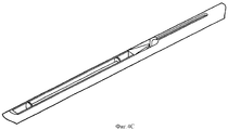
на фиг.4А - вид в перспективе альтернативного варианта осуществления челнока;on figa is a perspective view of an alternative embodiment of the shuttle;
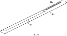
на фиг.4В - вид в перспективе опоры челнока;on figv is a perspective view of the support of the shuttle;
на фиг.4С - вид в перспективе челнока согласно фиг.4А, который помещается в опоре челнока, показанной на фиг.4В;on figs is a perspective view of the shuttle according to figa, which is placed in the support of the shuttle shown in figv;
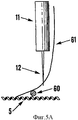
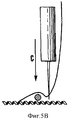
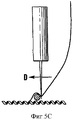
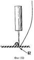
на фиг.5A-5D схематически показана работа устройства для прикрепления проволоки к поверхности трансплантата.on figa-5D schematically shows the operation of the device for attaching wire to the surface of the graft.
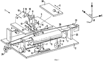
В соответствии с фиг.1 сшивное устройство 1 имеет основание 2, на котором установлен сшивающий манипулятор 10, трубка 20 челнока и стол 30 стента.According to FIG. 1, the stapler 1 has a base 2 on which a
Трансплантат 5 удерживает пара захватов (не показаны), которые расположены на каждом конце трансплантата 5, а через просвет трансплантата 5 проходит трубка 20 челнока, каждый конец которой опирается на опоры 25 трубки челнока, также установленные на основании 2.The
Сшивающий манипулятор 10 установлен на каретке 3, которую привод 4 перемещает параллельно и перпендикулярно трубке 20 челнока (по направлению стрелок А и В, соответственно), за счет чего сшивающий манипулятор 10 устанавливают в требуемое положение по отношению к трансплантату 5.The
Сшивающий манипулятор 10 имеет головку 11 иглы 12, выступающую за край каретки 3, при этом игла 12 способна перемешаться вверх и вниз относительно трансплантата 5 (в направлении стрелки С) и из стороны в сторону (так называемое «виляние иглы») под действием привода (в направлении стрелки D). Головка 11 иглы управляет развертыванием верхней нити (не показана), через ушко иглы 12 проходящей от катушки (не показана) до прошивателя 15 (которым управляет электродвигатель 16) и затем входящей в контакт с устройством 14 натяжения верхней нити.The
Проволоку, используемую для формирования стента на поверхности трансплантата 5, которой была предварительно придана соответствующая форма, укладывают на стол 30, который привод 31 перемещает в направлении стрелки Е в соответствующее положение по отношению к трансплантату 5. В процессе пришивания к трансплантату 5 проволоку (не показана) удерживает в соответствующем положении направляющая 32, прикрепленная к сшивающему манипулятору 10.The wire used to form the stent on the surface of the
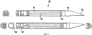
В соответствии с фиг.2 и 3 челнок 40 имеет бобину 41, на которой находится нижняя нить (не показана), и несущий элемент 44 бобины 41. Бобина 41 выполнена в форме удлиненной катушки с суженной центральной осью 42, вокруг которой наматывают нижнюю нить, и торцевые ролики 43, по которым катится бобина 41, за счет чего нить разматывается с оси 42. Бобина 41 свободно помещается в центральной полости несущего элемента 44, за счет чего нить легко разматывается с бобины 41.In accordance with figure 2 and 3, the
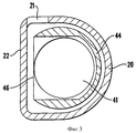
Несущий элемент 44 бобины имеет удлиненную форму и асимметричный носик 45, смещенный в боковом направлении от продольной оси несущего элемента 44 бобины, за счет чего он захватывает петлю верхней нити, что описано далее. Корпус несущего элемента 44 бобины (часть, отличающаяся от носика 45) имеет параллельные верхнюю и нижнюю стенки, соединенные плоской боковой стенкой 46 и изогнутой боковой стенкой, расположенной напротив боковой стенки 46. Данная конфигурация зеркально отражает конфигурацию внутренней полости трубки 20 челнока, за счет чего челнок 40 свободно помещается в трубке 20, при этом плоская боковая стенка 46 преимущественно параллельна плоской боковой стенке 22 трубки 20 челнока. Таким образом, челнок 40 способен перемещаться возвратно-поступательным образом вдоль трубки 20 челнока, однако не способен вращаться вокруг своей продольной оси, поскольку длина боковой стенки 46 превышает воображаемый внутренний диаметр изогнутого отрезка трубки 20 челнока.The
На фиг.2 и 3 показаны варианты осуществления, отличающиеся тем, что наружный профиль несущего элемента 44 бобины имеет незначительные различия. Тем не менее их функции неизменны, в частности, стенка 46 в обоих случаях служит для предотвращения возможности вращения несущего элемента 44 бобины в трубке 20 челнока.Figures 2 and 3 show embodiments, characterized in that the outer profile of the
На фиг.3 также показана прорезь 21 в трубке 20 челнока, через которую в процессе сшивания (описанном далее) проходит игла 12.Figure 3 also shows the slot 21 in the
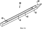
На фиг.4А показан альтернативный вариант осуществления челнока 50, имеющего бобину 41 с описанной выше центральной осью 42 и торцевыми роликами 43 и опору 51 бобины, форма которой преимущественно аналогична форме, описанной выше, несущего элемента 44 бобины за исключением того, что носик 52 опоры 51 бобины симметричен по форме в вертикальной плоскости, в которой проходит его продольная ось.FIG. 4A shows an alternative embodiment of a
На фиг.4С показан челнок 50, помещающийся в углублении 54 стержня 53 челнока, который показан на фиг.4В. Стержень 53 челнока также имеет прорезь 55, проходящую в вертикальной плоскости, в которой проходит его продольная ось.On figs shows the
В соответствии с фиг.1 приводной электродвигатель 26 челнока перемещает манипуляторы 23 челнока внутрь и из каждого конца трубки 20 челнока в направлении стрелки F, за счет чего челнок 40 перемещается вперед и назад вдоль трубки 20 челнока.According to FIG. 1, a
Устройство 24 натяжения нити челнока натягивает нижнюю нить на бобине 41 за счет увеличения давления на плоскую пружину 47 с целью захватить нижнюю нить под плоской пружиной 47 и тем самым создать натяжение.The
Положение трансплантата 5 по отношению к трубке 20 челнока регулируют при помощи привода 6, который перемещает подложку 7 (на которой лежит трансплантат 5) вверх и вниз относительно трубки 20 челнока (в направлении стрелки G) и из стороны в сторону параллельно продольной оси трубки 20 челнока (в направлении стрелки Н).The position of the
Если необходимо наклонить трансплантат 5 (например, в процессе прошивания поверхности на коническом участке), это делают при помощи привода 8, поднимающего и опускающего один конец трансплантата 5 в направлении стрелки I. При вращении захвата, расположенного с одного из концов трансплантата 5, он вращается вокруг своей продольной оси (в направлении стрелки J).If it is necessary to tilt the graft 5 (for example, during the flashing of the surface on a conical section), this is done with the help of a drive 8, raising and lowering one end of the
Далее работа сшивного устройства описана со ссылкой на фиг.1-3.Next, the operation of the stapler is described with reference to figures 1-3.
Трубку 20 челнока отсоединяют от опоры 25 и помещают трансплантат 5 поверх трубки 20 челнока, пропускают трансплантат 5 поверх трубки 20 челнока, в результате чего трубка 20 проходит через просвет трансплантата 5. Затем приводят в действие захваты трансплантата (не показаны) с целью захватить каждый из концов трансплантата 5 и правильно расположить трансплантат 5 по отношению к головке 11 иглы при помощи регулирующего положение подложки привода 6 и наклоняющего трансплантат привода 8. За счет вращения трансплантата 5 вокруг продольной оси его поверхность, к которой должна быть пришита армирующая проволока, обращена вверх в противоположную сторону от основания 2.The
Армирующую проволоку, из которой на трансплантате 5 формируют стент, предварительно формуют на столе 30, который помещают над плоскостью трансплантата 5 при помощи привода 31. При помощи направляющей 32 армирующую проволоку фиксируют над трансплантатом 5 на сшивающем манипуляторе 10, который, в свою очередь, фиксируют над трансплантатом при помощи привода 4, перемещающего каретку 3.The reinforcing wire, from which the stent is formed on the
В результате описанных операций армирующая проволока перемещается примерно в заданное положение по отношению к трансплантату 5. Армирующую проволоку устанавливают точно в заданное положение при помощи привода виляния иглы, что далее описано со ссылкой на фиг.5A-5D.As a result of the described operations, the reinforcing wire is moved to approximately a predetermined position with respect to the
Иглу 12, несущую верхнюю нить 61, сначала устанавливают вблизи армирующей проволоки 60 и затем опускают (по стрелке С), чтобы она оказалась непосредственно над поверхностью трансплантата 5. Затем иглу 12 перемещают в сторону (по стрелке D) при помощи привода виляния иглы с целью прижать проволоку 60 вплотную к предыдущему шву. Далее иглу 12 через стенку трансплантата 5 перемещают вниз в положение 62 вблизи проволоки 60.The
После того, как игла 12 полностью проткнет стенку трансплантата 5, она проходит через прорезь 21 в трубке 20 челнока, в результате чего конец иглы 12 перемещается в направлении наиболее удаленного от прорези 21 конца боковой стенки. Затем иглу 12 частично извлекают, в результате чего под действием силы трения, возникающей между верхней нитью и стенкой трансплантата 5, внутри трубки 20 челнока формируется петля.After the
Приводной электродвигатель 26 челнока приводит в действие манипулятор 23 челнока, который перемещает челнок вниз по трубке 20 в просвет трансплантата 5, при этом асимметричный носик 45 несущего элемента 44 бобины расположен спереди. По мере продвижения челнока 40 в направлении петли, образованной верхней нитью, носик 45 захватывает петлю, чему способствует асимметричное расположение носика 45 по отношению к плоской боковой стенке 46 несущего элемента 44 бобины. Нижнюю нить, обвитую вокруг центральной оси 42 бобины 41, тянет за собой челнок 40.The
После того, как челнок 40 захватит петлю, образованную верхней нитью, его перемещение прекращается, а игла 12 полностью выходит из стенки трансплантата 5, оставляя за собой петлю, образованную верхней нитью. Затем челнок 40 перемещается таким образом, что он полностью проходит через петлю, образованную верхней нитью, и выходит с другой стороны.After the
После того, как нижняя нить была пропущена поверх верхней нити, был сформирован шов. Это достигается за счет комбинированного действия устройства 14 натяжения верхней нити и прошивателя 15, который электродвигатель 16 перемещает вверх в противоположном от трансплантата 5 направлении, тем самым затягивая петлю на верхней нити. Одновременно устройство 14 натяжения верхней нити воздействует на верхнюю нить, создавая такое натяжение, которое способен преодолевать прошиватель 15, формируя шов. Аналогичным образом устройство 24 натяжения нити челнока прижимает плоскую пружину 47 к челноку 40, захватывая нижнюю нить и препятствуя ее разматыванию с катушки 41.After the bobbin thread was skipped over the top thread, a seam was formed. This is achieved due to the combined action of the
После формирования шва манипуляторы 23 челнока действуют в обратном направлении, перемещая челнок 40 из просвета трансплантата 5 и тем самым создавая пространство для повторного перемещения иглы 12 в трансплантат 5 и формирования очередной петли. Расположение второго шва выбирают таким образом, чтобы он проходил поверх армирующей проволоки и тем самым пришивал ее к трансплантату 5. Это достигается при помощи привода 13 виляния иглы, который перемещает иглу 12 таким образом, чтобы достичь точной установки иглы 12 в заданное положение по отношению к армирующей проволоке и трансплантату 5.After the formation of the suture, the
По мере пришивания армирующей проволоки к трансплантату 5 его положение по отношению к сшивающему манипулятору 10 непрерывно регулируют при помощи захватов трансплантата, регулирующего положение подложки привода 6 и наклоняющего трансплантат привода 8.As the reinforcing wire is sewn to the
В альтернативном варианте осуществления изобретения вместо челнока 40 используют челнок 50. Нить наматывают на бобину 41, которая помещается внутри несущего элемента 51, а несущий элемент 51 помещается в углублении 54 стержня 53 челнока, как это показано на фиг.4С. Стержень 53 перемещается возвратно-поступательным образом аналогично описанному перемещению челнока 40 в трубке 20 челнока. Игла 12 проходит через прорезь 55, а затем перемещается немного назад, формируя петлю. Стержень 53 продолжает перемещаться, и носик 52 входит в контакт с петлей. После этого формируют швы аналогично тому, как это описано выше.In an alternative embodiment of the invention, a
Несмотря на то, что в изобретении описано прошивание нитью трубчатого медицинского имплантата, который может представлять собой трансплантат, стент, трансплантат-стент, устройство фиксации трансплантата, армирующие устройства глазных орбит, кольцевые опоры сердечных клапанов, имплантаты, опоры венных клапанов или любые другие трубчатые медицинские формы, очевидно, что способ и устройство по изобретению могут в равной мере применяться для прошивания нитью поверхности любой трубчатой формы.Despite the fact that the invention describes the flashing of a tubular medical implant, which may be a graft, stent, graft-stent, graft fixation device, eye orbit reinforcing devices, ring supports of heart valves, implants, supports of venous valves or any other tubular medical forms, it is obvious that the method and device according to the invention can equally be used for flashing the surface of any tubular shape with a thread.
Очевидно, что элементы описанного устройства могут использоваться для достижения дополнительных целей, которые не были конкретно описаны. Например, устройство может быть использовано для формирования трехмерных текстильных структур, таких как структуры искусственной ткани или подложки для нее.Obviously, the elements of the described device can be used to achieve additional goals that were not specifically described. For example, the device can be used to form three-dimensional textile structures, such as artificial fabric structures or substrates for it.
Claims (19)
а. при помощи иглы, установленной на механическом сшивном устройстве, пропускают первую нить через стенку и далее в просвет имплантата,
b. формируют петлю из первой нити,
с. перемещают бобину, на которой находится вторая нить, в названный просвет через открытый конец имплантата,
d. пропускают вторую нить через петлю, образованную первой нитью,
е. затягивают названную петлю для формирования шва и
f. извлекают бобину из просвета,
при этом имплантат отклоняют таким образом, чтобы ось, вдоль которой перемещается бобина, проходила преимущественно параллельно стенке, в которой формируют шов.1. A method of flashing a wall of a tubular medical implant with a straight section, preferably with parallel walls, and at least one conical section with conical walls, comprising the steps of:
but. using a needle mounted on a mechanical stapler, pass the first thread through the wall and further into the lumen of the implant,
b. loop from the first thread
from. moving the bobbin, on which the second thread is located, into the named lumen through the open end of the implant,
d. pass the second thread through the loop formed by the first thread,
e. tighten the named loop to form a seam and
f. remove the bobbin from the lumen,
however, the implant is deflected so that the axis along which the reel moves passes mainly parallel to the wall in which the seam is formed.
а. опору имплантата,
b. иглу, установленную на механическом сшивном устройстве, для подачи первой нити через поверхность и далее в просвет имплантата,
с. бобину для второй нити,
d. средство перемещения бобины через открытый конец имплантата в упомянутый просвет с целью формирования шва в сочетании с первой нитью и
е. средство отклонения имплантата относительно направления перемещения имплантата.5. A device for flashing the surface of a tubular medical implant with a thread, including:
but. implant support
b. a needle mounted on a mechanical stapler to feed the first thread through the surface and further into the lumen of the implant,
from. spool for the second thread,
d. means for moving the bobbin through the open end of the implant into said lumen with the aim of forming a seam in combination with the first thread and
e. means for deflecting the implant relative to the direction of movement of the implant.
а. при помощи иглы, установленной на механическом сшивном устройстве, пропускают первую нить через стенку прямого участка имплантата и далее в просвет имплантата,
b. формируют петлю из первой нити,
с. перемещают бобину, на которой находится вторая нить, в названный просвет через открытый конец имплантата,
d. пропускают вторую нить через петлю, образованную первой нитью,
е. затягивают названную петлю с целью формирования шва,
f. извлекают бобину из просвета,
g. отклоняют имплантат таким образом, чтобы одна из стенок конусного участка имплантата была преимущественно параллельна направлению движения бобины, и
h. повторно осуществляют стадии a-f, чтобы сформировать шов в упомянутой конусной стенке.15. A method of flashing a wall of a tubular medical implant with a straight section, preferably with parallel walls, and at least one conical section with conical walls, comprising the steps of:
but. using a needle mounted on a mechanical stapler, pass the first thread through the wall of the straight portion of the implant and then into the lumen of the implant,
b. loop from the first thread
from. moving the bobbin, on which the second thread is located, into the named lumen through the open end of the implant,
d. pass the second thread through the loop formed by the first thread,
e. tighten the named loop in order to form a seam,
f. remove the bobbin from the lumen,
g. deflecting the implant so that one of the walls of the conical portion of the implant is predominantly parallel to the direction of movement of the reel, and
h. re-carry out the steps of af to form a seam in said conical wall.
Applications Claiming Priority (2)
| Application Number | Priority Date | Filing Date | Title |
|---|---|---|---|
| GBGB0110670.7A GB0110670D0 (en) | 2001-05-01 | 2001-05-01 | Machine for manufacturing graft-stents |
| GB0110670.7 | 2001-05-01 |
Related Parent Applications (1)
| Application Number | Title | Priority Date | Filing Date |
|---|---|---|---|
| RU2003132788/14A Division RU2297199C2 (en) | 2001-05-01 | 2002-05-01 | Method for manufacturing medical transplant-stent |
Publications (2)
| Publication Number | Publication Date |
|---|---|
| RU2006141499A RU2006141499A (en) | 2008-05-27 |
| RU2425656C2 true RU2425656C2 (en) | 2011-08-10 |
Family
ID=9913825
Family Applications (2)
| Application Number | Title | Priority Date | Filing Date |
|---|---|---|---|
| RU2003132788/14A RU2297199C2 (en) | 2001-05-01 | 2002-05-01 | Method for manufacturing medical transplant-stent |
| RU2006141499/14A RU2425656C2 (en) | 2001-05-01 | 2002-05-01 | Method of manufacturing tubular medical implant |
Family Applications Before (1)
| Application Number | Title | Priority Date | Filing Date |
|---|---|---|---|
| RU2003132788/14A RU2297199C2 (en) | 2001-05-01 | 2002-05-01 | Method for manufacturing medical transplant-stent |
Country Status (12)
| Country | Link |
|---|---|
| US (2) | US7073456B2 (en) |
| EP (1) | EP1385451A2 (en) |
| JP (1) | JP4287659B2 (en) |
| KR (2) | KR100949073B1 (en) |
| CN (2) | CN1286442C (en) |
| AU (2) | AU2002251350B2 (en) |
| BR (1) | BR0209377B1 (en) |
| CA (1) | CA2445975C (en) |
| GB (1) | GB0110670D0 (en) |
| MX (1) | MXPA03009953A (en) |
| RU (2) | RU2297199C2 (en) |
| WO (1) | WO2002087471A2 (en) |
Families Citing this family (23)
| Publication number | Priority date | Publication date | Assignee | Title |
|---|---|---|---|---|
| CA2497966C (en) * | 2002-09-19 | 2011-07-26 | Exstent Limited | Improvements in or relating to stents |
| US8246673B2 (en) * | 2002-09-19 | 2012-08-21 | Exstent Limited | External support for a blood vessel |
| GB0303002D0 (en) * | 2003-02-11 | 2003-03-12 | Vascutek Ltd | Sewing apparatus |
| GB0402796D0 (en) * | 2004-02-09 | 2004-03-10 | Anson Medical Ltd | An endoluminal surgical delivery system |
| DE102004039980B4 (en) | 2004-08-12 | 2019-08-01 | Aesculap Ag | Textile vascular prosthesis with a longitudinal bend |
| US7739971B2 (en) * | 2005-06-07 | 2010-06-22 | Edwards Lifesciences Corporation | Systems and methods for assembling components of a fabric-covered prosthetic heart valve |
| US8020503B2 (en) | 2006-07-31 | 2011-09-20 | Edwards Lifesciences Corporation | Automated surgical implant sewing system and method |
| EP2416840B1 (en) * | 2009-04-08 | 2015-09-16 | Saluda Medical Pty Limited | Stitched components of an active implantable medical device |
| KR100994459B1 (en) * | 2009-04-28 | 2010-11-16 | 윤상진 | Surgical suture instrument with sewing function |
| US8646397B2 (en) * | 2010-12-17 | 2014-02-11 | Midcon Cables Co., Inc. | Method and apparatus for producing machine stitched flat wiring harness |
| US8465504B2 (en) | 2011-01-25 | 2013-06-18 | Isuturing, Llc | Devices and methods for continuous surgical suturing |
| US9775602B2 (en) | 2011-01-25 | 2017-10-03 | Isuturing, Llc | Devices and methods for continuous surgical suturing |
| JP2014138628A (en) * | 2011-09-16 | 2014-07-31 | Midori Anzen Co Ltd | Sewing machine, workpiece and stent graft |
| US10880316B2 (en) | 2015-12-09 | 2020-12-29 | Check Point Software Technologies Ltd. | Method and system for determining initial execution of an attack |
| CN107333345B (en) * | 2017-08-08 | 2023-04-14 | 上海金洛安全装备有限公司 | Adsorption clamping heating member |
| IL275709B2 (en) | 2018-01-12 | 2025-06-01 | Edwards Lifesciences Corp | Automatic heart valve suturing |
| CN112236269B (en) * | 2018-01-25 | 2024-04-16 | 雷尼公司 | Semi-automatic precision positioning robot device and method |
| MY209173A (en) | 2018-08-22 | 2025-06-25 | Edwards Lifesciences Corp | Automated heart valve manufacturing devices and methods |
| CN111374795B (en) * | 2018-12-27 | 2021-12-07 | 上海微创投资控股有限公司 | Suture device for preparing implant |
| CN109938894B (en) * | 2019-01-24 | 2020-10-23 | 上海微创医疗器械(集团)有限公司 | Suture device for implant and method of suture |
| JP2023534384A (en) | 2020-06-09 | 2023-08-09 | エドワーズ ライフサイエンシーズ コーポレイション | Automatic sewing and thread management |
| JP2023546031A (en) | 2020-10-07 | 2023-11-01 | カナリー メディカル スウィッツァーランド アクチェンゲゼルシャフト | Providing medical devices with sensing functions |
| CN118680730A (en) * | 2024-07-05 | 2024-09-24 | 金仕生物科技(常熟)有限公司 | Artificial prosthesis |
Citations (3)
| Publication number | Priority date | Publication date | Assignee | Title |
|---|---|---|---|---|
| US5824040A (en) * | 1995-12-01 | 1998-10-20 | Medtronic, Inc. | Endoluminal prostheses and therapies for highly variable body lumens |
| US5824037A (en) * | 1995-10-03 | 1998-10-20 | Medtronic, Inc. | Modular intraluminal prostheses construction and methods |
| RU97122289A (en) * | 1996-12-26 | 1999-10-10 | Мединол Лтд. | METHOD AND DEVICE FOR PRODUCING A STENT |
Family Cites Families (25)
| Publication number | Priority date | Publication date | Assignee | Title |
|---|---|---|---|---|
| DE105121C (en) | ||||
| US2344846A (en) * | 1942-10-09 | 1944-03-21 | Berg Bernhard | Pliable reinforced ornament |
| US3316870A (en) * | 1964-03-27 | 1967-05-02 | Scovill Manufacturing Co | Method of making coil type zipper fastener stringers |
| US3600767A (en) * | 1969-06-17 | 1971-08-24 | Singer Co | Coil-type zipper stringer |
| US3714671A (en) * | 1970-11-30 | 1973-02-06 | Cutter Lab | Tissue-type heart valve with a graft support ring or stent |
| FR2315562A1 (en) | 1975-06-26 | 1977-01-21 | Commissariat Energie Atomique | METHOD AND DEVICES FOR MANUFACTURING BODIES OR PARTS FROM THREE-DIMENSIONAL FABRICS |
| US4414908A (en) | 1979-12-04 | 1983-11-15 | Janome Sewing Machine Co. Ltd. | Suturing machine for medical treatment |
| JPS6025144B2 (en) * | 1981-12-08 | 1985-06-17 | 株式会社新飯田製作所 | hand sewing machine |
| US4502159A (en) * | 1982-08-12 | 1985-03-05 | Shiley Incorporated | Tubular prostheses prepared from pericardial tissue |
| US4625664A (en) * | 1983-07-21 | 1986-12-02 | Duell Virginia B | Craft yarns |
| DE3824007A1 (en) * | 1988-07-15 | 1990-01-18 | Baeckmann Reinhard | Method and apparatus for stitch-weaving and weave-quilting |
| US4901661A (en) * | 1989-03-10 | 1990-02-20 | Sturm Lillian P | Decorative ribbon |
| US5226379A (en) * | 1990-08-20 | 1993-07-13 | Everett Sharon L | Process for edging openwork fabric and product produced thereby |
| US5489297A (en) * | 1992-01-27 | 1996-02-06 | Duran; Carlos M. G. | Bioprosthetic heart valve with absorbable stent |
| US5618290A (en) * | 1993-10-19 | 1997-04-08 | W.L. Gore & Associates, Inc. | Endoscopic suture passer and method |
| RU2089131C1 (en) * | 1993-12-28 | 1997-09-10 | Сергей Апполонович Пульнев | Stent-expander |
| WO1996036297A1 (en) * | 1995-05-19 | 1996-11-21 | Kanji Inoue | Transplantation instrument, method of bending same and method of transplanting same |
| US5755727A (en) * | 1995-06-02 | 1998-05-26 | Cardiologics L.L.C. | Method device for locating and sealing a blood vessel |
| GB9518400D0 (en) | 1995-09-08 | 1995-11-08 | Anson Medical Ltd | A surgical graft/stent system |
| GB9614950D0 (en) | 1996-07-16 | 1996-09-04 | Anson Medical Ltd | A ductus stent and delivery catheter |
| US5906759A (en) * | 1996-12-26 | 1999-05-25 | Medinol Ltd. | Stent forming apparatus with stent deforming blades |
| US6178903B1 (en) | 1997-04-01 | 2001-01-30 | L&P Property Management Company | Web-fed chain-stitch single-needle mattress cover quilter with needle deflection compensation |
| CA2318890C (en) | 1998-01-26 | 2007-05-22 | Anson Medical Limited | Reinforced graft |
| US6626917B1 (en) * | 1999-10-26 | 2003-09-30 | H. Randall Craig | Helical suture instrument |
| GB2355728A (en) | 1999-10-27 | 2001-05-02 | Anson Medical Ltd | Tubular medical implants and methods of manufacture |
-
2001
- 2001-05-01 GB GBGB0110670.7A patent/GB0110670D0/en not_active Ceased
-
2002
- 2002-05-01 AU AU2002251350A patent/AU2002251350B2/en not_active Ceased
- 2002-05-01 EP EP02720285A patent/EP1385451A2/en not_active Withdrawn
- 2002-05-01 RU RU2003132788/14A patent/RU2297199C2/en not_active IP Right Cessation
- 2002-05-01 US US10/476,349 patent/US7073456B2/en not_active Expired - Lifetime
- 2002-05-01 CA CA002445975A patent/CA2445975C/en not_active Expired - Fee Related
- 2002-05-01 KR KR1020097003911A patent/KR100949073B1/en not_active Expired - Fee Related
- 2002-05-01 CN CNB028090004A patent/CN1286442C/en not_active Expired - Fee Related
- 2002-05-01 JP JP2002584825A patent/JP4287659B2/en not_active Expired - Lifetime
- 2002-05-01 CN CN2006101321611A patent/CN1951339B/en not_active Expired - Fee Related
- 2002-05-01 RU RU2006141499/14A patent/RU2425656C2/en not_active IP Right Cessation
- 2002-05-01 MX MXPA03009953A patent/MXPA03009953A/en active IP Right Grant
- 2002-05-01 WO PCT/GB2002/001970 patent/WO2002087471A2/en not_active Ceased
- 2002-05-01 BR BRPI0209377-4A patent/BR0209377B1/en not_active IP Right Cessation
- 2002-05-01 KR KR1020037014222A patent/KR100933949B1/en not_active Expired - Fee Related
-
2006
- 2006-06-01 US US11/421,659 patent/US7290494B2/en not_active Expired - Lifetime
-
2007
- 2007-07-12 AU AU2007203240A patent/AU2007203240B2/en not_active Ceased
Patent Citations (3)
| Publication number | Priority date | Publication date | Assignee | Title |
|---|---|---|---|---|
| US5824037A (en) * | 1995-10-03 | 1998-10-20 | Medtronic, Inc. | Modular intraluminal prostheses construction and methods |
| US5824040A (en) * | 1995-12-01 | 1998-10-20 | Medtronic, Inc. | Endoluminal prostheses and therapies for highly variable body lumens |
| RU97122289A (en) * | 1996-12-26 | 1999-10-10 | Мединол Лтд. | METHOD AND DEVICE FOR PRODUCING A STENT |
Also Published As
| Publication number | Publication date |
|---|---|
| CA2445975C (en) | 2009-10-27 |
| WO2002087471A2 (en) | 2002-11-07 |
| RU2006141499A (en) | 2008-05-27 |
| KR100949073B1 (en) | 2010-03-25 |
| CN1514702A (en) | 2004-07-21 |
| US7073456B2 (en) | 2006-07-11 |
| AU2002251350B2 (en) | 2007-04-26 |
| AU2007203240A1 (en) | 2007-08-02 |
| KR20040024856A (en) | 2004-03-22 |
| CA2445975A1 (en) | 2002-11-07 |
| BR0209377B1 (en) | 2012-09-04 |
| AU2007203240B2 (en) | 2009-09-10 |
| EP1385451A2 (en) | 2004-02-04 |
| MXPA03009953A (en) | 2005-03-07 |
| KR20090036599A (en) | 2009-04-14 |
| GB0110670D0 (en) | 2001-06-20 |
| JP2004528903A (en) | 2004-09-24 |
| CN1286442C (en) | 2006-11-29 |
| US20060213416A1 (en) | 2006-09-28 |
| US20050013841A1 (en) | 2005-01-20 |
| CN1951339A (en) | 2007-04-25 |
| RU2297199C2 (en) | 2007-04-20 |
| RU2003132788A (en) | 2005-03-20 |
| US7290494B2 (en) | 2007-11-06 |
| JP4287659B2 (en) | 2009-07-01 |
| WO2002087471A3 (en) | 2003-09-25 |
| CN1951339B (en) | 2012-08-08 |
| KR100933949B1 (en) | 2009-12-28 |
| BR0209377A (en) | 2004-06-08 |
Similar Documents
| Publication | Publication Date | Title |
|---|---|---|
| RU2425656C2 (en) | Method of manufacturing tubular medical implant | |
| RU2254060C2 (en) | Method for manufacturing medical implants and device for suturing tubular medical implant walls | |
| AU2002251350A1 (en) | Method for manufacturing stent-grafts | |
| US4747358A (en) | Surgical suturing machine | |
| JP2018530681A (en) | Loom equipped with a device for holding, supplying and inserting a weft thread in a loom shed and a method for holding, supplying and inserting a weft thread in a loom shed | |
| CN109938894B (en) | Suture device for implant and method of suture | |
| CN111374795A (en) | Suture device for preparing implant | |
| KR101790268B1 (en) | A automatic suturing device | |
| KR101990064B1 (en) | Suture apparatus having sewing function | |
| RU93047168A (en) | BINDING MACHINE | |
| US20060070563A1 (en) | Sewing apparatus and method | |
| KR20180118415A (en) | A film of attached suture for suturing device |
Legal Events
| Date | Code | Title | Description |
|---|---|---|---|
| MM4A | The patent is invalid due to non-payment of fees |
Effective date: 20170502 |