RU2425356C1 - Device for measuring physical and mechanical properties of materials - Google Patents
Device for measuring physical and mechanical properties of materials Download PDFInfo
- Publication number
- RU2425356C1 RU2425356C1 RU2009142298/28A RU2009142298A RU2425356C1 RU 2425356 C1 RU2425356 C1 RU 2425356C1 RU 2009142298/28 A RU2009142298/28 A RU 2009142298/28A RU 2009142298 A RU2009142298 A RU 2009142298A RU 2425356 C1 RU2425356 C1 RU 2425356C1
- Authority
- RU
- Russia
- Prior art keywords
- rod
- indenter
- fixed
- free part
- free
- Prior art date
Links
Images
Landscapes
- Investigating Or Analyzing Materials By The Use Of Ultrasonic Waves (AREA)
- Investigating Strength Of Materials By Application Of Mechanical Stress (AREA)
Abstract
Description
Изобретение относится к технике контроля материалов и изделий и может быть использовано для измерения параметров рельефа поверхности (линейные размеры, шероховатость) и механических характеристик материалов (твердость, модуль упругости) с субмикронным и нанометровым пространственным разрешением.The invention relates to techniques for controlling materials and products and can be used to measure surface topography (linear dimensions, roughness) and mechanical characteristics of materials (hardness, elastic modulus) with submicron and nanometer spatial resolution.
В настоящее время с развитием нанотехнологий все более актуальной становится задача измерений свойств материалов в нанометровом диапазоне линейных размеров. Для широкого спектра материалов и изделий важнейшим параметром являются качество обработки и структура поверхности, а также механические свойства: твердость, модуль упругости, трещиностойкость, адгезия и др. В частности, эти параметры важны для конструкционных материалов, защитных тонких пленок, медицинских покрытий, поверхностей ответственных деталей, изделий микроэлектроники и микросистемной техники и др. Для измерения перечисленных выше параметров чаще всего применяют приборы следующих основных типов: сканирующие зондовые микроскопы (СЗМ) и наноинденторы. СЗМ применяют в основном для исследования рельефа поверхности, а также изучения свойств тонких приповерхностных слоев. В качестве зондов СЗМ, в частности, так называемых сканирующих силовых микроскопов, используют кремниевые кантилеверы, производимые по интегральной технологии, с радиусом острия иглы менее 20 нм. Достоинством таких приборов является высокое разрешение и качество получаемых изображений поверхности, недостатком - невозможность измерения механических свойств твердых материалов из-за малой изгибной жесткости зондов и относительно низкого значения твердости материала наконечника. В нанотвердомерах используются алмазные наконечники (инденторы), что позволяет измерять свойства практически всех известных материалов. Используемые системы для задания и регистрации силы и перемещения позволяют прикладывать нагрузку с разрешением в микроньютоны и контролировать внедрение индентора с разрешением в доли нанометра. До недавнего времени существенным недостатком серийных нанотвердомеров было отсутствие методов визуализации поверхности до и после нанесения отпечатка. В современных приборах для решения этой задачи используют дополнительные головки СЗМ, что приводит к значительному удорожанию прибора и усложнению процедуры измерений. Также ведущие производители использует режим сканирования поверхности алмазным индентором с контролем силы прижима индентора к поверхности, однако особенности конструкции датчиков наноинденторов не позволяют получать изображения с качеством, сопоставимым с возможностями СЗМ. В связи с этим актуальной является задача создания устройств, позволяющих исследовать рельеф поверхности с нанометровым пространственным разрешением и измерять механические свойства различных материалов. Одним из возможных подходов для решения данной задачи является использование режима колебаний зонда для определения контакта наконечника с поверхностью.Currently, with the development of nanotechnology, the task of measuring the properties of materials in the nanometer range of linear dimensions is becoming increasingly relevant. For a wide range of materials and products, the most important parameter is the quality of processing and surface structure, as well as mechanical properties: hardness, elastic modulus, crack resistance, adhesion, etc. In particular, these parameters are important for structural materials, protective thin films, medical coatings, and critical surfaces parts, products of microelectronics and microsystem technology, etc. To measure the above parameters, the following main types of devices are most often used: scanning probe micros ops (SPM) and nanoindenter. SPM is mainly used to study the surface topography, as well as to study the properties of thin near-surface layers. As probes SPM, in particular, the so-called scanning force microscopes, silicon cantilevers made by integrated technology with a needle tip radius of less than 20 nm are used. The advantage of such devices is the high resolution and quality of the obtained surface images, the disadvantage is the inability to measure the mechanical properties of solid materials due to the low bending stiffness of the probes and the relatively low hardness of the tip material. Nanohardness testers use diamond tips (indenters), which makes it possible to measure the properties of almost all known materials. The systems used for setting and recording the force and displacement allow applying a load with a resolution in micronewtons and controlling the indenter introduction with a resolution of a fraction of a nanometer. Until recently, a significant drawback of serial nanosolid testers was the lack of surface visualization methods before and after printing. In modern devices, additional SPM heads are used to solve this problem, which leads to a significant increase in the cost of the device and the complexity of the measurement procedure. Leading manufacturers also use the surface scanning mode with a diamond indenter to control the force of the indenter clamping to the surface, however, the design features of the nanoindenter sensors do not allow obtaining images with a quality comparable to the SPM capabilities. In this regard, the urgent task is to create devices that allow to study the surface topography with nanometer spatial resolution and measure the mechanical properties of various materials. One of the possible approaches to solving this problem is to use the oscillation mode of the probe to determine the contact of the tip with the surface.
На сегодняшний день известны устройства, реализующие акустический метод измерения механических характеристик материалов, основанный на механическом контакте индентора с поверхностью. Реализация данного метода заключается в следующем. Индентор колеблется с некоторой резонансной частотой и амплитудой. При контакте индентора с поверхностью исследуемого объекта частота и амплитуда колебаний изменяются в результате воздействия на резонансную систему со стороны материала в области контакта. По характеру этого изменения судят о механических характеристиках материала под индентором (патент Германии 4306243, кл. G01N 3/40, 1993).Today, devices are known that implement the acoustic method of measuring the mechanical characteristics of materials based on the mechanical contact of the indenter with the surface. The implementation of this method is as follows. The indenter oscillates with a certain resonant frequency and amplitude. When the indenter contacts the surface of the test object, the frequency and amplitude of the oscillations change as a result of exposure to the resonance system from the material side in the contact area. By the nature of this change, the mechanical characteristics of the material under the indenter are judged (German patent 4306243, CL G01N 3/40, 1993).
Наиболее близким техническим решением предлагаемого устройства является устройство для измерения механических характеристик материалов (патент РФ №2108561, кл. G01N 3/40, 1996), представляющее собой резонатор в виде стержня пьезоматериала, состоящий из двух половин, имеющий два внешних электрода и разделительный электрод. Один внешний электрод и разделительный электрод подключены к схеме возбуждения, вырабатывающей переменное напряжение определенной частоты и амплитуды. Электронная схема детектирования осуществляет измерение амплитуды и частоты (фазы) колебаний напряжения, возникающего на втором внешнем электроде в результате прямого пьезоэффекта. К одному из внешних электродов и разделительному электроду подключен выход управляемого источника постоянного напряжения. Один конец стержня жестко закреплен в держателе. На другом конце на боковой грани закреплен индентор. Дополнительно устройство может быть снабжено стержнем с электродами, аналогичным основному стержню с аналогично подключенными электродами и соединенным одним концом с основным стержнем в месте его крепления в держателе, образуя совместно с ним камертон. Резонатор дополнительно подключен к схеме возбуждения в качестве частотозадающего элемента и составляет с ней автогенератор.The closest technical solution of the proposed device is a device for measuring the mechanical characteristics of materials (RF patent No. 2108561, class G01N 3/40, 1996), which is a resonator in the form of a piezomaterial rod, consisting of two halves, having two external electrodes and a separation electrode. One external electrode and a separation electrode are connected to an excitation circuit generating an alternating voltage of a certain frequency and amplitude. The electronic detection circuit measures the amplitude and frequency (phase) of voltage fluctuations that occur at the second external electrode as a result of the direct piezoelectric effect. The output of a controlled constant voltage source is connected to one of the external electrodes and the separation electrode. One end of the rod is rigidly fixed in the holder. At the other end, an indenter is fixed on the side face. Additionally, the device can be equipped with a rod with electrodes similar to the main rod with similarly connected electrodes and connected at one end to the main rod in the place of its mounting in the holder, forming together with it a tuning fork. The resonator is additionally connected to the excitation circuit as a frequency-setting element and constitutes an oscillator with it.
Недостатком прототипа является то, что схема возбуждения, обеспечивающая высокочастотные гармонические колебания стержня и управляемый источник напряжения, служащий для медленного управляемого изгиба стержня с целью поддержания контакта индентора с поверхностью, подключены к одному и тому же стержню. Изгиб стержня под воздействием управляемого источника напряжения приводит к изменению электроакустических и механических параметров стержня, что в свою очередь изменяет резонансную частоту и добротность стержня как колебательной системы. Из-за этого при изгибе стержня происходит изменение детектируемых сигналов частоты и амплитуды, что ухудшает чувствительность устройства. Кроме того, использование одного и того же стержня ограничивает диапазон функциональных характеристик устройства. Резонансная частота стержня f и ее изгиб h при заданном диапазоне управляющего напряжения и толщине непосредственно связаны между собой следующим образом: f·h=const. Увеличение резонансной частоты с целью повышения быстродействия датчика приводит при прочих равных условиях к уменьшению диапазона изгиба стержня, что ограничивает возможную высоту рельефа поверхностей, доступных для исследования.The disadvantage of the prototype is that the excitation circuit, providing high-frequency harmonic oscillations of the rod and a controlled voltage source, used for slow controlled bending of the rod in order to maintain contact of the indenter with the surface, are connected to the same rod. The bending of the rod under the influence of a controlled voltage source leads to a change in the electro-acoustic and mechanical parameters of the rod, which in turn changes the resonant frequency and quality factor of the rod as an oscillatory system. Because of this, when the rod bends, the detected signals of frequency and amplitude change, which affects the sensitivity of the device. In addition, the use of the same rod limits the range of functional characteristics of the device. The resonant frequency of the rod f and its bending h for a given range of control voltage and thickness are directly related to each other as follows: f · h = const. An increase in the resonance frequency in order to increase the speed of the sensor, ceteris paribus, leads to a decrease in the range of bending of the rod, which limits the possible height of the relief of the surfaces available for research.
Задачей предлагаемого изобретения является повышение быстродействия и чувствительности устройства и расширение его функциональных возможностей.The task of the invention is to increase the speed and sensitivity of the device and expand its functionality.
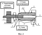
Поставленная задача решается тем, что в устройстве, содержащем пьезоэлектрический стержень с двумя внешними и одним разделительным электродом, один конец которого закреплен в держателе, а на другом конце размещен индентор, схему возбуждения, схему детектирования и управляемый источник напряжения, пьезоэлектрический стержень выполнен составным из закрепленной в держателе и свободной частей, причем свободная часть выполнена как продолжение закрепленной и скреплена с ней, управляемый источник напряжения подключен к закрепленной части, индентор размещен на конце свободной части, один внешний электрод свободной части стержня соединен со схемой возбуждения, другой внешний электрод соединен со схемой детектирования (фиг.1). Кроме того, устройство может быть снабжено дополнительным пьезоэлектрическим стержнем, аналогичным свободной части составного стержня, таким образом, что они все вместе образуют камертонную конструкцию, в которой закрепленная часть составного стержня является ножкой камертона, а свободная часть составного стержня и дополнительный стержень образуют ветви камертона, причем схемы возбуждения и детектирования подключены к разным ветвям камертона (фиг.2).The problem is solved in that in a device containing a piezoelectric rod with two external and one dividing electrode, one end of which is fixed in the holder, and the indenter, the excitation circuit, the detection circuit and the controlled voltage source are placed on the other end, the piezoelectric rod is made of a fixed in the holder and the free parts, the free part being made as a continuation of the fixed and fastened with it, the controlled voltage source is connected to the fixed part, the indenter is located at the end of the free part, one external electrode of the free part of the rod is connected to the excitation circuit, the other external electrode is connected to the detection circuit (Fig. 1). In addition, the device can be equipped with an additional piezoelectric rod, similar to the free part of the composite rod, so that together they form a tuning fork structure, in which the fixed part of the composite rod is the fork of the tuning fork, and the free part of the composite rod and the additional rod form the branches of the tuning fork, moreover, the excitation and detection circuits are connected to different branches of the tuning fork (figure 2).
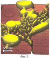
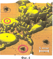
На фиг.1 показана общая схема устройства с составным стержнем. На фиг.2 показано устройство в виде камертона. На фиг.3 представлено 3-мерное изображение участка поверхности алюминиевого сплава марки Д16. На фиг.4 представлено изображение поверхности алюминиевого сплава марки Д16 с отпечатками после индентирования.Figure 1 shows a General diagram of a device with a composite rod. Figure 2 shows a device in the form of a tuning fork. Figure 3 presents a 3-dimensional image of the surface area of the aluminum alloy brand D16. Figure 4 presents the image of the surface of the aluminum alloy brand D16 with prints after indentation.
Устройство представляет собой (фиг.1) стержень 1 из пьезоматериала в виде двухслойных (биморфных) пластин, имеющих наружные электроды 2 и внутренние электроды 3, причем стержень выполнен составным из 2 частей, одна из которых жестко закреплена концом в держателе 7, а на свободном конце другой зафиксирован индентор 8. К одному из электродов свободной части стержня с индентором подключена схема возбуждения 4, вырабатывающая переменное напряжение определенной частоты и амплитуды. Электронная схема детектирования 5 осуществляет измерение амплитуды и частоты (фазы) колебаний напряжения, возникающего на другом электроде свободной части стержня в результате прямого пьезоэффекта. К одному из электродов закрепленной части стержня подключен выход управляемого источника постоянного напряжения 6. Остальные электроды подключены к общей земляной шине схем управления 9, детектирования и управляемого источника напряжения.The device is (Fig. 1) a
На фиг.2 представлено устройство, отличающееся тем, что оно снабжено дополнительным пьезоэлектрическим стержнем 1.1, аналогичным свободной части составного стержня 1, таким образом, что вместе они образуют камертонную конструкцию, в которой закрепленная часть составного стержня является ножкой камертона и закреплена в держателе 7, а свободная часть составного стержня и дополнительный стержень являются ветвями камертона. Схемы возбуждения 4 и схема детектирования 5 подключены к разным ветвям камертона.Figure 2 presents the device, characterized in that it is equipped with an additional piezoelectric rod 1.1, similar to the free part of the
Устройство работает следующим образом. При помощи схемы возбуждения 4 в свободной части стержня 1 за счет обратного пьзоэффекта инициируют изгибные колебания путем подачи переменного напряжения на некоторой частоте. При этом амплитуду и частоту (фазу) колебаний измеряют при помощи схемы детектирования 5 путем обработки электрического сигнала, возникающего в результате прямого пьезоэффекта. Затем систему, состоящую из держателя 7 и стержня 1 с индентором 8, устанавливают так, чтобы индентор 8 находился в непосредственной близости от исследуемой поверхности. Плавно изменяют напряжение на выходе управляемого источника 6. В результате действия обратного пьезоэффекта закрепленная часть стержня 1 изгибается и перемещает индентор 8 к поверхности до касания. Касание фиксируют по изменению параметров колебаний свободной части стержня 1 (амплитуды или фазы), измеряемых схемой детектирования 5. Управляют источником 6 таким образом, чтобы изменения амплитуды или частоты (фазы) колебаний оставались постоянными. Для сканирования профиля рельефа поверхности перемещают устройство вдоль поверхности, изгибая при этом стержень 1 с помощью управляемого источника 6 таким образом, чтобы измеряемый схемой детектирования параметр (изменение амплитуды колебаний или частоты) оставался постоянным. При этом записывают сигнал источника 6, который соответствует профилю поверхности. Для измерения механических свойств поверхности вводят индентор в контакт с поверхностью и затем увеличивают изгибающее напряжение на выходе управляемого источника 6 на заданную величину, нагружая тем самым индентор с заданным усилием и производя индентирование. Последующее сканирование поверхности позволяет измерить площадь полученных отпечатков и рассчитать по ним твердость исследуемого материала.The device operates as follows. Using the excitation circuit 4 in the free part of the
Устройство описанной конструкции было использовано в качестве зонда сканирующего зондового микроскопа НаноСкан (СЗМ). Для исследования был выбран алюминиевый сплав Д16. Поверхность образца была предварительно полирована и затем протравлена для выявления отдельных фаз и включений. Процедура исследования состояла в следующем. Образец алюминиевого сплава помещали на предметный стол сканера СЗМ. Зонд, выполненный в виде описанного устройства, подводили к поверхности образца с помощью микропозиционера с приводом от шагового двигателя до касания индентора 8 с поверхностью. Амплитуда колебаний стержня 1 при этом была порядка 100 нм, частота 11,5 кГц. Касание фиксировали по изменению частоты колебаний стержня 1, измеряемых схемой детектирования 5. Затем, подавая напряжение на выходе управляемого источника 6, удерживали с помощью системы обратной связи прижим индентора 8 к поверхности так, чтобы изменение частоты относительно свободных колебаний оставалось постоянным и составляло 10 Гц. После этого образец перемещали в горизонтальной плоскости с помощью сканера СЗМ так, чтобы происходило построчное сканирование его поверхности индентором 8 на площади 20×20 мкм. В процессе сканирования меняли изгиб стержня 1, изменяя напряжение на выходе управляемого источника 6 так, чтобы частота колебаний стержня 1 оставалась постоянной. При этом измеряли и фиксировали значения напряжения на выходе управляемого источника 6. Значения напряжения на выходе управляемого источника 6 использовали для построения изображения рельефа поверхности (фиг.3). Затем с помощью сканера СЗМ располагали образец так, чтобы зонд оказывался в точке поверхности, выбранной для измерений. Изменяя напряжение управляемого источника 6 вводили индентор 8 в контакт с поверхностью до изменения частоты колебаний зонда на 10 Гц и затем изменяли напряжение на величину, обеспечивающую нагружение индентора на величину 10 мН, производя индентирование. Описанную процедуру осуществляли в разных местах поверхности, соответствующих разным компонентам материала на полученном изображении. Последующее сканирование поверхности позволило измерить площадь полученных отпечатков (фиг.4) и рассчитать по ним твердость отдельных фаз исследуемого материала. Значение твердости основной компоненты составило ~2 ГПа, упрочняющей фазы ~8 ГПа.The device of the described construction was used as a probe of a scanning probe microscope NanoScan (SPM). An aluminum alloy D16 was chosen for the study. The surface of the sample was pre-polished and then etched to identify individual phases and inclusions. The research procedure was as follows. A sample of the aluminum alloy was placed on the object table of the SPM scanner. The probe, made in the form of the described device, was brought to the surface of the sample using a micropositioner driven from a stepper motor until the
Использование составного стержня позволило разделить измерительную колеблющуюся часть, на которой находится индентор, и изгибающуюся часть, служащую для поддержания контакта с поверхностью. В результате удалось существенно (более чем в 10 раз) уменьшить зависимость резонансной частоты и установившейся амплитуды колебаний стержня от его изгиба. Кроме того, изменяя длину закрепленной части, можно произвольно изменять диапазон перемещения индентора при одинаковых диапазонах изгибающего напряжения, не изменяя при этом резонансные свойства свободной (измерительной части). В частности, диапазон перемещения индентора был увеличен с 5 мкм до 20 мкм и боле по сравнению с параметрами прототипа.The use of a composite rod made it possible to separate the measuring oscillating part, on which the indenter is located, and the bending part, which serves to maintain contact with the surface. As a result, it was possible to significantly (more than 10 times) reduce the dependence of the resonant frequency and the steady-state amplitude of the oscillations of the rod from its bending. In addition, by changing the length of the fixed part, it is possible to arbitrarily change the range of movement of the indenter at the same bending stress ranges, without changing the resonance properties of the free (measuring part). In particular, the range of movement of the indenter was increased from 5 μm to 20 μm and more compared to the parameters of the prototype.
Применение камертонной конструкции позволило повысить добротность и чувствительность устройства, а также снизить зависимость параметров зонда от акустических и механических характеристик места закрепления. Это происходит благодаря локализации акустических колебаний. Подключение схем возбуждения и детектирования к разным ветвям камертона уменьшает проникновение паразитного электрического сигнала и повышает чувствительность зонда к механическому контакту с поверхностью. Заземление внешних электродов повышает помехозащищенность устройства.The use of a tuning fork design made it possible to increase the quality factor and sensitivity of the device, as well as to reduce the dependence of the probe parameters on the acoustic and mechanical characteristics of the fixing point. This is due to the localization of acoustic vibrations. Connecting the excitation and detection circuits to different branches of the tuning fork reduces the penetration of a spurious electrical signal and increases the sensitivity of the probe to mechanical contact with the surface. Grounding of the external electrodes increases the noise immunity of the device.
Устройство описанной конструкции было использовано в качестве зонда сканирующего зондового микроскопа (СЗМ) «НаноСкан». Большинство современных СЗМ с полем сканирования в плоскости XY до 100 мкм имеют диапазон измерения высоты рельефа по Z координате не более 10 мкм. Использование описанного устройства позволило обеспечить диапазон сканирования по Z до 20 мкм и более, что существенно увеличило удобство работы с прибором.The device of the described construction was used as a probe of a scanning probe microscope (SPM) "NanoScan". Most modern SPMs with a scanning field in the XY plane of up to 100 μm have a range of measuring the height of the relief along the Z coordinate of no more than 10 μm. Using the described device allowed to provide a scanning range of Z up to 20 microns or more, which significantly increased the usability of the device.
Claims (2)
Priority Applications (1)
| Application Number | Priority Date | Filing Date | Title |
|---|---|---|---|
| RU2009142298/28A RU2425356C1 (en) | 2009-11-18 | 2009-11-18 | Device for measuring physical and mechanical properties of materials |
Applications Claiming Priority (1)
| Application Number | Priority Date | Filing Date | Title |
|---|---|---|---|
| RU2009142298/28A RU2425356C1 (en) | 2009-11-18 | 2009-11-18 | Device for measuring physical and mechanical properties of materials |
Publications (2)
| Publication Number | Publication Date |
|---|---|
| RU2009142298A RU2009142298A (en) | 2011-05-27 |
| RU2425356C1 true RU2425356C1 (en) | 2011-07-27 |
Family
ID=44734351
Family Applications (1)
| Application Number | Title | Priority Date | Filing Date |
|---|---|---|---|
| RU2009142298/28A RU2425356C1 (en) | 2009-11-18 | 2009-11-18 | Device for measuring physical and mechanical properties of materials |
Country Status (1)
| Country | Link |
|---|---|
| RU (1) | RU2425356C1 (en) |
Cited By (2)
| Publication number | Priority date | Publication date | Assignee | Title |
|---|---|---|---|---|
| RU167852U1 (en) * | 2016-06-01 | 2017-01-20 | Федеральное государственное бюджетное научное учреждение "Технологический институт сверхтвердых и новых углеродных материалов" (ФГБНУ ТИСНУМ) | DEVICE FOR MEASURING MECHANICAL PROPERTIES OF MATERIALS |
| RU2731039C1 (en) * | 2019-09-17 | 2020-08-28 | Федеральное государственное бюджетное учреждение науки "Институт машиноведения им. А.А. Благонравова Российской академии наук (ИМАШ РАН) | Device for measuring surface relief parameters and mechanical properties of materials |
-
2009
- 2009-11-18 RU RU2009142298/28A patent/RU2425356C1/en active
Cited By (2)
| Publication number | Priority date | Publication date | Assignee | Title |
|---|---|---|---|---|
| RU167852U1 (en) * | 2016-06-01 | 2017-01-20 | Федеральное государственное бюджетное научное учреждение "Технологический институт сверхтвердых и новых углеродных материалов" (ФГБНУ ТИСНУМ) | DEVICE FOR MEASURING MECHANICAL PROPERTIES OF MATERIALS |
| RU2731039C1 (en) * | 2019-09-17 | 2020-08-28 | Федеральное государственное бюджетное учреждение науки "Институт машиноведения им. А.А. Благонравова Российской академии наук (ИМАШ РАН) | Device for measuring surface relief parameters and mechanical properties of materials |
Also Published As
| Publication number | Publication date |
|---|---|
| RU2009142298A (en) | 2011-05-27 |
Similar Documents
| Publication | Publication Date | Title |
|---|---|---|
| JP2730673B2 (en) | Method and apparatus for measuring physical properties using cantilever for introducing ultrasonic waves | |
| US8037762B2 (en) | Whispering gallery mode ultrasonically coupled scanning probe microscopy | |
| Rabe et al. | Evaluation of the contact resonance frequencies in atomic force microscopy as a method for surface characterisation | |
| US7861577B2 (en) | Electric potential difference detection method and scanning probe microscope | |
| JP5813966B2 (en) | Displacement detection mechanism and scanning probe microscope using the same | |
| WO2007072706A1 (en) | Scan type probe microscope | |
| Chung et al. | Accurate noncontact calibration of colloidal probe sensitivities in atomic force microscopy | |
| CN101776436A (en) | Quartz tuning fork-based nano measuring head and sample surface micro-topography measuring method | |
| RU2425356C1 (en) | Device for measuring physical and mechanical properties of materials | |
| RU2442131C1 (en) | Method for measuring surface texture properties and mechanical properties of the materials | |
| Sanz et al. | Laser vibrometry and impedance characterization of piezoelectric microcantilevers | |
| Rupp et al. | Nonlinear contact resonance spectroscopy in atomic force microscopy | |
| JP4758405B2 (en) | Sensor element and physical sensor device | |
| Szoszkiewicz et al. | Adhesion hysteresis and friction at nanometer and micrometer lengths | |
| Wang et al. | Critical electrode size in measurement of d33 coefficient of films via spatial distribution of piezoelectric displacement | |
| JP6001728B2 (en) | Displacement detection mechanism and scanning probe microscope using the same | |
| JP5225284B2 (en) | Electromechanical property inspection method for electromechanical transducer | |
| Schmidt et al. | Experimental and theoretical analysis of shear–force interaction in the non-contact regime with 100 pN force resolution | |
| RU2108561C1 (en) | Gear measuring mechanical characteristics of materials | |
| RU2731039C1 (en) | Device for measuring surface relief parameters and mechanical properties of materials | |
| Fu et al. | A comparative study of piezoelectric unimorph and multilayer actuators as stiffness sensors via contact resonance | |
| RU2193769C2 (en) | Method measuring characteristics of surface magnetic field with use of scanning sounding microscope | |
| US20060288786A1 (en) | Ultrasonically coupled scanning probe microscope | |
| RU2428700C2 (en) | Control unit for scanning probe microscopes | |
| RU2124251C1 (en) | Multiprobe cantilever for scanning probe microscope |