RU2419373C2 - Dispenser with simple feed of sheet article - Google Patents
Dispenser with simple feed of sheet article Download PDFInfo
- Publication number
- RU2419373C2 RU2419373C2 RU2009116634/12A RU2009116634A RU2419373C2 RU 2419373 C2 RU2419373 C2 RU 2419373C2 RU 2009116634/12 A RU2009116634/12 A RU 2009116634/12A RU 2009116634 A RU2009116634 A RU 2009116634A RU 2419373 C2 RU2419373 C2 RU 2419373C2
- Authority
- RU
- Russia
- Prior art keywords
- housing
- side walls
- dispenser
- cover
- lid
- Prior art date
Links
Images
Classifications
-
- A—HUMAN NECESSITIES
- A47—FURNITURE; DOMESTIC ARTICLES OR APPLIANCES; COFFEE MILLS; SPICE MILLS; SUCTION CLEANERS IN GENERAL
- A47K—SANITARY EQUIPMENT; ACCESSORIES THEREFOR, e.g. TOILET ACCESSORIES
- A47K10/00—Body-drying implements; Toilet paper; Holders therefor
- A47K10/24—Towel dispensers; Toilet paper dispensers
- A47K10/32—Dispensers for paper towels or toilet paper
- A47K10/34—Dispensers for paper towels or toilet paper dispensing from a web, e.g. with mechanical dispensing means
- A47K10/36—Dispensers for paper towels or toilet paper dispensing from a web, e.g. with mechanical dispensing means with mechanical dispensing, roll switching or cutting devices
- A47K10/3687—Dispensers for paper towels or toilet paper dispensing from a web, e.g. with mechanical dispensing means with mechanical dispensing, roll switching or cutting devices with one or more reserve rolls
-
- A—HUMAN NECESSITIES
- A47—FURNITURE; DOMESTIC ARTICLES OR APPLIANCES; COFFEE MILLS; SPICE MILLS; SUCTION CLEANERS IN GENERAL
- A47K—SANITARY EQUIPMENT; ACCESSORIES THEREFOR, e.g. TOILET ACCESSORIES
- A47K10/00—Body-drying implements; Toilet paper; Holders therefor
- A47K10/24—Towel dispensers; Toilet paper dispensers
- A47K10/32—Dispensers for paper towels or toilet paper
- A47K10/34—Dispensers for paper towels or toilet paper dispensing from a web, e.g. with mechanical dispensing means
- A47K10/36—Dispensers for paper towels or toilet paper dispensing from a web, e.g. with mechanical dispensing means with mechanical dispensing, roll switching or cutting devices
- A47K2010/3681—Dispensers for paper towels or toilet paper dispensing from a web, e.g. with mechanical dispensing means with mechanical dispensing, roll switching or cutting devices characterised by the way a new paper roll is loaded in the dispenser
Landscapes
- Health & Medical Sciences (AREA)
- Public Health (AREA)
- Closures For Containers (AREA)
- Unwinding Webs (AREA)
- Cartons (AREA)
- Toilet Supplies (AREA)
Abstract
Description
Настоящее раскрытие в целом относится к диспенсерам листового изделия и, более конкретно, относится к диспенсерам листового изделия для раздачи листового изделия из рулонов.The present disclosure generally relates to dispensers of a sheet product and, more particularly, relates to dispensers of a sheet product for dispensing a sheet product from rolls.
Раздача листовых изделий, таких как бумажные полотенца, туалетная бумага и тому подобных, общепринята в торговых предприятиях, таких как рестораны, аэропорты, торговые центры, станции технического обслуживания и так далее. Бумажные изделия раздаются в этих предприятиях благодаря применению диспенсеров, зачастую диспенсеров, которые содержат в себе множество рулонов изделия. Диспенсеры такого рода регулярно требуют перезагрузки. Таким образом, важным критерием для выбора диспенсера является простота, с которой диспенсер может быть перезагружен.Distribution of sheet products, such as paper towels, toilet paper and the like, is generally accepted in commercial enterprises such as restaurants, airports, shopping centers, service stations and so on. Paper products are distributed in these enterprises through the use of dispensers, often dispensers that contain many rolls of the product. Dispensers of this kind regularly require a reboot. Thus, an important criterion for choosing a dispenser is the simplicity with which the dispenser can be restarted.
Следовательно, существует постоянная необходимость в диспенсерах листового изделия, которые легко загружать.Therefore, there is a continuing need for sheet product dispensers that are easy to load.
В данном документе раскрыты диспенсеры листового изделия.Dispensers of a sheet product are disclosed herein.
В одном варианте осуществления изобретения диспенсер содержит крышку; заднюю часть корпуса; шарнир, соединяющий заднюю часть корпуса и крышку так, что крышка может поворачиваться в промежутке между открытым положением и закрытым положением, причем крышка и задняя часть корпуса совместно образуют корпус диспенсера; первый и второй крепежный кронштейн, соединенный с задней частью корпуса; и вращающийся карусельный механизм, подвижно установленный на первый и второй крепежный кронштейн, где кронштейны и карусельный механизм спроектированы таким образом, что карусельный механизм может двигаться в промежутке между внутренним заблокированным положением для раздачи и внешним вращающимся положением для перезагрузки.In one embodiment, the dispenser comprises a lid; the back of the case; a hinge connecting the rear of the housing and the lid so that the lid can rotate between the open position and the closed position, the lid and the rear of the housing together forming a dispenser housing; the first and second mounting bracket connected to the rear of the housing; and a rotating carousel mechanism, movably mounted on the first and second mounting bracket, where the brackets and carousel mechanism are designed so that the carousel mechanism can move between the internal locked position for distribution and the external rotating position for reloading.
В одном варианте осуществления изобретения диспенсер спроектирован для раздачи рулонного листового изделия, причем диспенсер включает в себя крепление для рулонов листового изделия и корпус с задней панелью, верхней стенкой, передней стенкой и парой расположенных в плане напротив друг друга боковых стенок и содержит крышку, образующую переднюю стенку диспенсера, а также участки боковых стенок корпуса диспенсера, расположенные в плане напротив друг друга, крышку, оборудованную парой выступающих в плане усеченных куполов в боковых стенках, причем плоскости сечения каждого купола в общем параллельны задней панели, каждый выступающий в плане усеченный купол в боковой стенке, в общем примыкающий к задней панели и фронтально описываемый дугообразной круглой линией, направленной наружу в данном виде и вперед относительно задней панели; заднюю часть корпуса, образующую заднюю панель корпуса и участки пары боковых стенок, расположенных в плане напротив друг друга, заднюю часть корпуса, спроектированную для образования пары прорезей в боковых стенках, расположенных в плане напротив друг друга, продолжающихся в основном к задней панели задней части корпуса и соответствующих в основном размеру и форме заднего участка выступающих в плане усеченных куполов боковых стенок крышки, по меньшей мере, либо заднюю часть корпуса, либо крышку, образующую, по меньшей мере, участок верхней стенки; и шарнир, соединяющий заднюю часть корпуса и крышку так, что крышка может поворачиваться в промежутке между открытым положением и закрытым положением, в котором выступающие в плане усеченные купола в боковых стенках крышки расположены, спроектированы так и имеют такой размер, чтобы образовывать боковые стенки корпуса около крепления рулона, когда корпус находится в закрытом положении, и обеспечивать в основном беспрепятственный доступ к креплению рулона, когда крышка находится в открытом положении.In one embodiment of the invention, the dispenser is designed for dispensing a rolled sheet product, the dispenser comprising a holder for rolls of the sheet product and a housing with a back panel, top wall, front wall and a pair of side walls arranged in opposite plan and comprises a cover defining a front the wall of the dispenser, as well as portions of the side walls of the dispenser housing, located in the plan opposite to each other, a cover equipped with a pair of truncated domes protruding in the plan in the side walls ah, wherein each dome section plane generally parallel to the rear panel, each truncated dome projecting plane in the sidewall, generally adjacent to the rear and frontal line of the circular arc described by outward in this manner and forward relative to the back panel; the back of the casing, forming the rear panel of the casing and portions of a pair of side walls located in a plan opposite to each other, the rear part of the casing, designed to form a pair of slots in the side walls, located in a plan opposite to each other, extending mainly to the rear panel of the rear of the casing and corresponding mainly to the size and shape of the rear portion, the lateral walls of the lid protruding in plan of the truncated domes, at least either the rear of the housing or the lid forming at least a portion of the top s wall; and a hinge connecting the rear of the housing and the lid so that the lid can rotate between the open position and the closed position, in which the truncated domes projecting in plan in the side walls of the lid are designed and are sized to form the side walls of the housing about securing the roll when the housing is in the closed position, and to provide substantially unhindered access to the securing of the roll when the cover is in the open position.
В одном варианте осуществления изобретения диспенсер спроектирован для раздачи рулонов листового изделия, причем диспенсер включает в себя крепление для рулонов листового изделия и корпус с задней панелью, верхней стенкой, передней стенкой и парой расположенных в плане напротив друг друга боковых стенок, также он содержит крышку, образующую переднюю стенку диспенсера, а также участки боковых стенок корпуса диспенсера, расположенных в плане напротив друг друга, по меньшей мере, одну боковую стенку крышки, оборудованную выступом, направленным назад, причем выступ, направленный назад, в общем упирается в заднюю панель; заднюю часть корпуса, образующую тыльную сторону корпуса, и участки пары боковых стенок, расположенных в плане напротив друг друга, заднюю часть корпуса, спроектированную для образования, по меньшей мере, одной прорези в боковой стенке, продолжающейся в основном к тыльной стороне задней части корпуса и соответствующей в основном размеру и форме заднего участка выступа в крышке, направленного назад, по меньшей мере, либо заднюю часть корпуса, либо крышку, образующую, по меньшей мере, участок верхней стенки; и шарнир, соединяющий заднюю часть корпуса и крышку так, что крышка может поворачиваться в промежутке между открытым положением и закрытым положением, в котором выступы в крышке, направленные назад, расположены и спроектированы так и имеют такой размер, чтобы образовывать участки боковых стенок корпуса около установленного для раздачи рулона, когда корпус находится в закрытом положении, и обеспечивать по существу беспрепятственный доступ к креплению рулона, когда крышка находится в открытом положении.In one embodiment of the invention, the dispenser is designed to distribute rolls of sheet products, the dispenser including a holder for rolls of sheet products and a housing with a back panel, top wall, front wall and a pair of side walls arranged in opposite plan, also includes a cover, at least one side wall of the lid equipped with a protrusion forming a front wall of the dispenser, as well as portions of the side walls of the dispenser housing, arranged in plan opposite to each other back, the protrusion directed back generally abuts against the rear panel; the back of the case, forming the back side of the case, and portions of a pair of side walls located in plan opposite to each other, the back of the case, designed to form at least one slot in the side wall, extending mainly to the rear side of the back of the case and corresponding mainly to the size and shape of the rear portion of the protrusion in the lid, directed backward, at least either the rear of the housing, or the lid forming at least a portion of the upper wall; and a hinge connecting the rear of the housing and the cover so that the cover can rotate between the open position and the closed position, in which the protrusions in the cover, directed backward, are designed and designed so that they form portions of the side walls of the housing near the installed to distribute the roll when the housing is in the closed position, and to provide substantially unhindered access to the roll mount when the cover is in the open position.
Вышеописанные и другие признаки поясняются далее в подробном описании и на приложенных чертежах.The above and other features are explained further in the detailed description and in the attached drawings.
Одинаковые элементы на разных чертежах пронумерованы одинаково:Identical elements in different drawings are numbered the same:
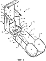
Фиг.1 - вид в перспективе корпуса диспенсера в открытом положении.Figure 1 is a perspective view of the dispenser housing in the open position.
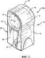
Фиг.2 - вид в перспективе корпуса диспенсера в закрытом положении.Figure 2 is a perspective view of the dispenser housing in the closed position.
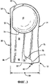
Фиг.3 - вид сбоку диспенсера.Figure 3 is a side view of the dispenser.
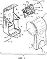
Фиг.4 - диспенсер в разобранном виде, изображающем различные детали.Figure 4 - disassembled dispenser, depicting various details.
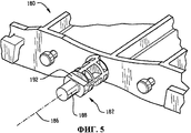
Фиг.5 - увеличенный вид, изображающий опорный выступ и фиксирующий упор рамы карусельного механизма диспенсера.5 is an enlarged view depicting a support protrusion and a locking stop of the frame of the carousel mechanism of the dispenser.
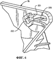
Фиг.6 - увеличенный вид, изображающий кронштейн диспенсера.6 is an enlarged view depicting a dispenser bracket.
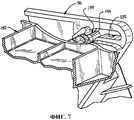
Фиг.7 - схематическое изображение, показывающее вал крепления карусельного механизма при внутреннем заблокированном положении для раздачи; иFig. 7 is a schematic view showing a shaft of a carousel mechanism with an internal locked position for dispensing; and
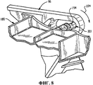
Фиг.8 - схематическое изображение, показывающее вал крепления карусельного механизма при внешнем вращающемся положении, предназначенном для перезагрузки диспенсера.Fig. 8 is a schematic view showing a shaft of a carousel mechanism in an external rotating position for resetting a dispenser.
Диспенсеры листового изделия, которые делают возможной простую загрузку рулонов листового изделия, раскрыты в документе. Диспенсер листового изделия может использоваться с одним или несколькими рулонами. Термин "листовое изделие" подразумевает натуральный и/или синтетический материал или бумажные листы. Более того, листовые изделия могут представлять собой как тканый, так и нетканый материал. Примерами листовых изделий служат носовые платки, салфетки, туалетная бумага и полотенца, но ими не ограничиваются.Sheet product dispensers that enable simple loading of sheet product rolls are disclosed in the document. The sheet product dispenser may be used with one or more rolls. The term "sheet product" means a natural and / or synthetic material or paper sheets. Moreover, sheet products can be both woven and non-woven material. Examples of sheet products include, but are not limited to, handkerchiefs, napkins, toilet paper, and towels.
Ссылаясь далее на Фиг.1-4, показан типовой корпус диспенсера, обозначенный позицией 12. Материалами, пригодными для изготовления корпуса 12, служат металл и пластик, но ими не ограничиваются. Для упрощения и снижения стоимости производства, в одном варианте осуществления изобретения, компоненты диспенсера содержат изготовленную литьем под давлением конструкцию, сделанную из термопластичного материала, такого как тот, что включает, по меньшей мере, один из следующих полимеров: акрилонитрил-бутадиен-стирольные (АБС) полимеры; полиакрилатные полимеры; поликарбонатные полимеры; полистирольные полимеры и стирол-акриловые сополимеры.Referring next to FIGS. 1-4, a typical dispenser case is indicated at 12. The materials suitable for making the
Корпус 12 в общем включает в себя крышку 14, образующую переднюю стенку 16 диспенсера 10. Крышка 14 включает в себя пару выступающих назад частей 18, 20 купола в боковых стенках. Части 18, 20 купола в боковых стенках продолжаются назад на большую величину, чем примыкающие участки 22, 24 боковых стенок крышки 14. Корпус 12 также имеет заднюю часть корпуса 30, которая включает пару расположенных сбоку участков 32, 34, боковых стенок, а также пару расположенных в плане напротив друг друга углублений 36, 38 в боковых стенках, соответствующих размеру и положению, по меньшей мере, около окружности 41 торца рулона 40 листового изделия, который устанавливается в диспенсер 10. Размер частей 18, 20 купола в боковых стенках изменяется в зависимости от предполагаемого листового изделия, применяемого в диспенсере 10. Например, в варианте осуществления изобретения может применяться рулон туалетной бумаги диаметром D, как правило, около 4 дюймов.The
Задняя часть корпуса 30 образовывает верхнюю стенку 42 диспенсера 10. Шарнир 48 соединяет крышку 14 и заднюю часть корпуса 30 так, что крышка 14 может поворачиваться между открытым положением 49а, показанным на Фиг.1, и закрытым положением 49b, показанным на Фиг.2. Шарнир 48 включает ряд отлитых как одно целое крепежей стержня 53 на задней части корпуса 30, а также стержень шарнира 50 и ряд отлитых как одно целое крепежей стержня 54 на крышке 14.The rear of the
Части куполов в боковых стенках 18, 20 крышки 14 и углубления 36, 38 в боковых стенках задней части корпуса 30 расположены, спроектированы и имеют размер так, что они взаимодействуют, чтобы образовать боковые стенки корпуса 12 около рулона 40, установленного для раздачи, когда корпус 12 находится в закрытом положении 49b, и обеспечивать в основном беспрепятственный доступ к рулону 40, когда крышка 14 находится в открытом положении 49а.Parts of the domes in the
В одном варианте осуществления изобретения углубления 36, 38 сделаны в общем в виде дуги, и части 18, 20 куполов в боковых стенках крышки 14 также образуют дуги. Например, части 18, 20 куполов в боковых стенках могут быть выступающими частями усеченной сферы. Углубления 36, 38, сделанные в виде дуги, задней части корпуса 30 и части 18, 20 куполов в боковых стенках крышки 14, продолжаются в основном до задней панели 52 корпуса 12, который может быть установлен, например, на универсальной монтажной пластине, прикрепленной к стене. Части 18, 20 куполов в боковых стенках расположены в верхнем участке 62 крышки 14, тогда как углубления 36, 38 расположены в верхнем участке 64 задней части корпуса 30. Задняя часть корпуса 30 включает пару участков 66, 68 боковых стенок, расположенных напротив друг друга, продолжающихся наружу от нижнего центрального участка 70, а крышка 14 включает пару соответствующих или совпадающих углублений 71, 73 в крышке, продолжающихся по направлению к передней стенке 16 нижнего участка 72 крышки 14. Разные углубления и выступы взаимодействуют, входя в зацепление, как показано, так, что крышка 14 надежно держится на задней части корпуса 30 с помощью ряда горизонтально продолжающихся сегментов 74, 76, 78 и 80, образованных между ними, когда крышка 14 находится в закрытом положении 49b.In one embodiment of the invention, the
В одном варианте осуществления изобретения задняя часть корпуса 30 дополнительно образует нижнюю стенку 82, которая продолжается более чем на 50% горизонтального пролета 84 между тыльной стороной 86 диспенсера 10 и передней стенкой 16 для того, чтобы отвечать требованиям опорной платформы для ведущего шасси, например, а также образует основное отверстие для раздачи 90, расположенное в среднем участке 92 нижней стенки 82. Задняя часть корпуса 30 также включает в себя пару крепежных кронштейнов 94, 96, расположенных напротив друг друга, для установки карусельного механизма в сборе 100.In one embodiment of the invention, the rear of the
В одном варианте осуществления изобретения карусельный узел 100 закрыт, когда корпус 12 находится в закрытом положении 49b. Верхнее крепление 150 карусельного механизма в сборе 100 в основном ничем не заслонено, когда раздаточное устройство 10 открыто, например, для перезагрузки. Части 18, 20 куполов в боковых стенках имеют форму усеченной сферы, выступающие в сторону от примыкающей краев боковых стенок крышки и продолжающиеся назад в целом к примыкающей задней панели 52. Со стороны задней панели 52 части 18, 20 куполов боковых стенок усечены так, что плоскости сечения каждой части 18, 20 куполов в боковых стенках в общем параллельны задней панели 52.In one embodiment, the
Ссылаясь на Фиг.4-8, где показано более подробно, что карусельный узел 100 включает в себя основание оправки 160, фиксаторы вала 162, 164, а также опорные валы оправки (также называемые как держатели рулона) 166, 168, которые могут соответственно включать в себя часть втулки. Несущий каркас оправки 180 с осевыми креплениями 182 вдоль центральной оси вращения 186. Крепления 182 имеют участки 188 круглого профиля, а также фиксирующие уступы 192. Для того чтобы обеспечить более компактный диспенсер, карусельный узел 100 перемещается между внутренним заблокированным положением для раздачи и внешним вращающимся положением для раздачи.Referring to FIGS. 4-8, where it is shown in more detail that the
Фиг.5 - увеличенный вид крепления 182 (также называемого как опорный выступ 182) рамы 180, изображающий участок круглого профиля 188, а также и уступ 192. Кронштейны 94, 96 задней части корпуса 30 включают в себя наклоненные, удлиненные прорези 220 с основным горизонтальным участком и продолжающимся вниз концевым участком 221, примыкающим к дорожке 222. Более детально, дорожка 222 примыкает по оси к прорези 220 вдоль оси 186 рамы 180, когда всевозможные компоненты установлены, как показано.5 is an enlarged view of the mount 182 (also referred to as the support protrusion 182) of the
Когда карусельный узел 100 установлен на кронштейны 94, 96 с помощью рамы 180, рама 180 (и, следовательно, карусельный узел 100 равным образом) может двигаться в промежутке между внутренним заблокированным положением 199, изображенным на Фиг.7, когда уступ входит в зацепление с дорожкой 222, и внешним вращающимся положением 201, изображенным на Фиг.8, когда ось 186 рамы 180 сместилась наружу для того, чтобы обеспечить зазор относительно тыльной стороны 52 задней части корпуса 30 для того, чтобы карусельный узел 100 мог вращаться в направлении, обозначенном стрелкой 224, для перезагрузки.When the
Преимущество раскрытого диспенсера заключается в легкой перезагрузке. Более того, карусельный узел 100 позволяет использовать более одного рулона листового изделия. При применении нескольких рулонов риск того, что листовое изделие закончится, значительно менее вероятен, при этом способность дает перемещать ось вращения 186 карусельного узла 100 наружу для вращения, обеспечивается благодаря компактной форме диспенсера.An advantage of the disclosed dispenser is its easy reset. Moreover, the
Так как настоящее изобретение описывается со ссылкой на пример варианта осуществления изобретения, то для специалиста в области техники является очевидным, что возможны различные модификации, и разные элементы могут быть эквивалентно заменены, не выходя за рамки изобретения. Кроме того, различные модификации могут быть сделаны согласно настоящему изобретению с адаптацией под конкретные условия или материал, не выходя за его рамки. Таким образом, изобретение не ограничивается конкретным вариантом осуществления изобретения, раскрытым как лучший вариант, рассматриваемый для осуществления изобретения, причем изобретение будет включать все варианты осуществления изобретения, попадающие в рамки прилагаемой формулы изобретения.Since the present invention is described with reference to an example embodiment of the invention, it is obvious to a person skilled in the technical field that various modifications are possible and different elements can be equivalently replaced without departing from the scope of the invention. In addition, various modifications can be made according to the present invention with adaptation to specific conditions or material, without going beyond its scope. Thus, the invention is not limited to the specific embodiment of the invention disclosed as the best option considered for carrying out the invention, and the invention will include all embodiments of the invention falling within the scope of the attached claims.
Claims (18)
крышку;
заднюю часть корпуса;
шарнир, соединяющий заднюю часть корпуса и крышку так, что крышка может поворачиваться между открытым положением и закрытым положением, причем крышка и задняя часть корпуса совместно образуют корпус диспенсера;
первый и второй крепежный кронштейн, соединенные с задней частью корпуса; и
вращающийся карусельный механизм, установленный с возможностью съема на первый и второй крепежный кронштейн, причем кронштейны и карусельный механизм спроектированы таким образом, что карусельный механизм может перемещаться между внутренним заблокированным положением для раздачи и внешним вращающимся положением для перезагрузки.1. Dispenser containing:
cover;
the back of the case;
a hinge connecting the rear of the housing and the lid so that the lid can rotate between the open position and the closed position, the lid and the rear of the housing together forming a dispenser housing;
the first and second mounting bracket connected to the rear of the housing; and
a rotating carousel mounted on the first and second mounting bracket, the brackets and carousel are designed so that the carousel can be moved between the internal locked position for distribution and the external rotating position for reloading.
крышка образует переднюю стенку диспенсера, а также участки боковых стенок корпуса диспенсера, расположенных напротив друг друга, причем крышка оборудована парой выступающих в боковом направлении усеченных куполов в боковых стенках, причем плоскости сечения каждого из куполов в целом параллельны задней панели, причем каждый выступающий в боковом направлении усеченный купол в боковой стенке, в общем примыкающий к задней панели и фронтально описываемый дугообразной кольцевой линией, проходящей наружу от него и вперед относительно задней панели;
задняя часть корпуса образует заднюю панель корпуса и участки пары боковых стенок, расположенных напротив друг друга, причем задняя часть корпуса спроектирована так, чтобы образовать пару углублений в боковых стенках, расположенных напротив друг друга, проходящих, по существу, к задней панели задней части корпуса и, по существу, соответствующих размеру и форме заднего участка выступающих в плане усеченных куполов боковых стенок крышки;
по меньшей мере, либо задняя часть корпуса либо крышка образуют, по меньшей мере, участок верхней стенки; и
выступающие в плане усеченные купола в боковых стенках крышки расположены и спроектированы так и имеют такой размер, чтобы, по существу, образовывать боковые стенки корпуса около установленного рулона листового изделия, когда корпус находится в закрытом положении, и обеспечивать, по существу, беспрепятственный доступ к креплению рулона, когда крышка находится в открытом положении.4. The dispenser according to claim 1, in which
the lid forms the front wall of the dispenser, as well as portions of the side walls of the dispenser body located opposite each other, and the lid is equipped with a pair of laterally projected truncated domes in the side walls, and the section planes of each of the domes are generally parallel to the rear panel, each protruding in the side direction, a truncated dome in the side wall, generally adjacent to the rear panel and frontally described by an arcuate annular line extending outward from it and forward relative to the rear second panel;
the rear part of the body forms the rear panel of the body and portions of a pair of side walls located opposite each other, and the rear part of the body is designed to form a pair of recesses in the side walls located opposite each other, passing essentially to the rear panel of the rear part of the body and essentially corresponding to the size and shape of the rear portion of the projected in plan truncated domes of the side walls of the cover;
at least either the back of the housing or the cover forms at least a portion of the upper wall; and
truncated domes projecting in plan in the side walls of the lid are arranged and designed in such a way that they essentially form the side walls of the housing near the installed roll of the sheet product when the housing is in the closed position and provide essentially unhindered access to the mount roll when the cover is in the open position.
крышку, образующую переднюю стенку диспенсера, а также участки боковых стенок корпуса диспенсера, расположенные напротив друг друга, крышка оборудована парой выступающих в боковом направлении усеченных куполов в боковых стенках, причем плоскость сечения каждого купола, по существу, параллельна задней панели, причем каждый выступающий в боковом направлении усеченный купол боковой стенки, по существу, примыкающий к задней панели и фронтально описываемый дугообразной кольцевой линией, направленной наружу от него и вперед относительно задней панели;
заднюю часть корпуса, образующую заднюю панель корпуса и участки пары боковых стенок, расположенных напротив друг друга, причем задняя часть корпуса спроектирована для образования пары углублений в боковых стенках, расположенных напротив друг друга, продолжающихся, по существу, к задней панели задней части корпуса и соответствующих, по существу, размеру и форме заднего участка выступающих в плане усеченных куполов боковых стенок крышки, причем, по меньшей мере, либо задняя часть корпуса, либо крышка образуют, по меньшей мере, участок верхней стенки; и
шарнир, соединяющий заднюю часть корпуса и крышку так, что крышка может поворачиваться между открытым положением и закрытым положением, причем выступающие в боковом направлении усеченные купола в боковых стенках крышки так расположены и спроектированы и имеют размер, чтобы в основном образовывать боковые стенки корпуса около крепления рулона, когда корпус находится в закрытом положении, и обеспечивать, по существу, беспрепятственный доступ к креплению рулона, когда крышка находится в открытом положении.11. Dispenser designed to distribute a rolled sheet product, including a holder for rolls of sheet product and a housing with a back panel, upper wall, front wall and a pair of side walls located opposite each other and containing:
a lid forming the front wall of the dispenser, as well as portions of the side walls of the dispenser body located opposite each other, the lid is equipped with a pair of laterally projected truncated domes in the side walls, and the plane of the cross section of each dome is essentially parallel to the rear panel, each protruding in the lateral direction of the truncated dome of the side wall, essentially adjacent to the rear panel and frontally described by an arcuate annular line directed outward from it and forward relatively behind panel days;
the back of the casing, forming the rear panel of the casing and portions of a pair of side walls located opposite each other, and the back of the casing is designed to form a pair of recesses in the side walls located opposite each other, extending essentially to the rear panel of the rear of the casing essentially the size and shape of the rear portion of the projected truncated domes of the side walls of the lid, at least either the rear of the housing or the lid form at least a portion of the top her walls; and
a hinge connecting the rear of the housing and the cover so that the cover can rotate between the open position and the closed position, and the laterally projected truncated domes in the side walls of the cover are so arranged and designed and sized to basically form the side walls of the housing near the roll mount when the housing is in the closed position, and to provide substantially unhindered access to the roll mount when the cover is in the open position.
крышку, образующую переднюю стенку диспенсера, а также участки боковых стенок корпуса диспенсера, расположенные напротив друг друга, по меньшей мере, одну боковую стенку крышки, оборудованную выступом, направленным назад, причем выступ направлен назад и примыкает к задней панели;
заднюю часть корпуса, образующую тыльную сторону корпуса и участки пары боковых стенок, расположенных напротив друг друга, причем задняя часть корпуса спроектирована так, чтобы образовать, по меньшей мере, одно углубление в боковой стенке, продолжающееся, по существу, к тыльной стороне задней части корпуса и соответствующее, по существу, размеру и форме заднего участка выступа в крышке, направленного назад, причем, по меньшей мере, либо задняя часть корпуса, либо крышка, образуют, по меньшей мере, участок верхней стенки; и
шарнир, соединяющий заднюю часть корпуса и крышку так, что крышка может поворачиваться между открытым положением и закрытым положением, причем выступ в крышке, направленный назад, так расположен и спроектирован и имеет такой размер, чтобы, по существу, образовывать участок боковой стенки корпуса около установленного для раздачи рулона, когда корпус находится в закрытом положении и обеспечивает, по существу, беспрепятственный доступ к креплению рулона, когда крышка находится в открытом положении. 18. Dispenser designed to distribute rolls of sheet products, including a holder for rolls of sheet products and a housing with a back panel, top wall, front wall and a pair of side walls located opposite each other, containing:
a cover forming the front wall of the dispenser, as well as portions of the side walls of the dispenser housing, located opposite each other, at least one side wall of the cover equipped with a protrusion directed backward, and the protrusion is directed back and adjacent to the rear panel;
the rear part of the housing, forming the rear side of the housing and sections of a pair of side walls located opposite each other, and the rear part of the housing is designed to form at least one recess in the side wall, continuing essentially to the rear side of the rear of the housing and corresponding essentially to the size and shape of the rear portion of the protrusion in the cover directed backward, wherein at least either the rear of the housing or the cover forms at least a portion of the upper wall; and
a hinge connecting the rear of the housing and the cover so that the cover can rotate between the open position and the closed position, and the protrusion in the cover, directed back, is so designed and designed so that it essentially forms a portion of the side wall of the housing near the installed for distributing the roll when the housing is in the closed position and provides substantially unhindered access to the roll mount when the cover is in the open position.
Applications Claiming Priority (2)
| Application Number | Priority Date | Filing Date | Title |
|---|---|---|---|
| US84891606P | 2006-10-03 | 2006-10-03 | |
| US60/848,916 | 2006-10-03 |
Publications (2)
| Publication Number | Publication Date |
|---|---|
| RU2009116634A RU2009116634A (en) | 2010-11-10 |
| RU2419373C2 true RU2419373C2 (en) | 2011-05-27 |
Family
ID=39111408
Family Applications (1)
| Application Number | Title | Priority Date | Filing Date |
|---|---|---|---|
| RU2009116634/12A RU2419373C2 (en) | 2006-10-03 | 2007-10-03 | Dispenser with simple feed of sheet article |
Country Status (7)
| Country | Link |
|---|---|
| US (2) | US7568652B2 (en) |
| EP (1) | EP2066209A2 (en) |
| CN (1) | CN101522086A (en) |
| CA (2) | CA2848429A1 (en) |
| MX (1) | MX2009003433A (en) |
| RU (1) | RU2419373C2 (en) |
| WO (1) | WO2008042969A2 (en) |
Families Citing this family (30)
| Publication number | Priority date | Publication date | Assignee | Title |
|---|---|---|---|---|
| RU2455916C2 (en) | 2006-10-03 | 2012-07-20 | Джорджия-Пэсифик Консьюмер Продактс Лп | Automated dispenser for paper towels |
| US7568652B2 (en) * | 2006-10-03 | 2009-08-04 | Georgia-Pacific Consumer Products Lp | Easy load sheet product dispenser |
| US7887005B2 (en) | 2007-09-12 | 2011-02-15 | Innovia Intellectual Properties, Llc | Easy-load household automatic paper towel dispenser |
| WO2010141931A2 (en) | 2009-06-06 | 2010-12-09 | Innovia Intellectual Properties, Llc | Automatic paper towel dispenser apparatus |
| US8356767B2 (en) * | 2009-12-15 | 2013-01-22 | Sca Tissue North America Llc | Dispenser for multiple rolls of web material with automatic roll transfer, and method of loading same |
| CN102905592A (en) * | 2010-05-27 | 2013-01-30 | Sca卫生用品公司 | Dispensers for absorbent tissue or nonwoven materials |
| US9861238B2 (en) * | 2010-11-03 | 2018-01-09 | Solaris Paper, Inc. | Spindle adapter for roll paper product dispensers |
| USD664796S1 (en) | 2011-05-31 | 2012-08-07 | Georgia-Pacific France | Paper dispenser |
| USD664795S1 (en) | 2011-05-31 | 2012-08-07 | Georgia-Pacific France | Paper dispenser |
| US9138110B2 (en) * | 2011-07-25 | 2015-09-22 | Wausau Paper Towel & Tissue, Llc | Tissue dispenser, method for dispensing tissue, and tissue dispenser insert |
| FR2982525A1 (en) | 2011-11-15 | 2013-05-17 | Ingenico Sa | PAPER ROLLER PRINTER, PAYMENT TERMINAL, PAPER ROLL AND CORRESPONDING PLACING METHOD |
| MX366593B (en) * | 2012-05-29 | 2019-07-15 | Gpcp Ip Holdings Llc | Sheet product dispenser with load inducement portion. |
| US20140374434A1 (en) * | 2013-06-19 | 2014-12-25 | David C.T. Jour | Notepaper Dispensing Box |
| US10602887B2 (en) | 2013-08-23 | 2020-03-31 | Gpcp Ip Holdings Llc | Towel dispensers |
| US9596964B1 (en) | 2013-08-23 | 2017-03-21 | Innovia Intellectual Properties, Llc | Wall mounted towel dispensers |
| US9642503B1 (en) | 2013-08-25 | 2017-05-09 | Innovia Intellectual Properties, Llc | Portable, vertically oriented automatic towel dispenser apparatus |
| MX383288B (en) | 2014-08-08 | 2025-03-13 | Gpcp Ip Holdings Llc | LEAF PRODUCT DISPENSERS AND RELATED METHODS FOR REDUCING LEAF PRODUCT USE. |
| US10143340B2 (en) * | 2015-06-17 | 2018-12-04 | Essity Hygiene And Health Aktiebolag | Dispenser assembly and related methods |
| US11412900B2 (en) | 2016-04-11 | 2022-08-16 | Gpcp Ip Holdings Llc | Sheet product dispenser with motor operation sensing |
| US11395566B2 (en) | 2016-04-11 | 2022-07-26 | Gpcp Ip Holdings Llc | Sheet product dispenser |
| AT519204B1 (en) * | 2016-09-16 | 2018-10-15 | Georg Hagleitner Hans | donor |
| US10660485B2 (en) * | 2017-10-09 | 2020-05-26 | Gpcp Ip Holdings Llc | Dual roll product dispenser with rotating refill carriage |
| US10850938B2 (en) | 2017-10-09 | 2020-12-01 | Gpcp Ip Holdings Llc | Mechanical sheet product dispenser |
| IT201700117734A1 (en) * | 2017-10-18 | 2019-04-18 | Sofidel Spa | DISPENSER OF ROLLED MATERIALS |
| US11825993B2 (en) | 2018-07-09 | 2023-11-28 | Gpcp Ip Holdings Llc | Spindle and cover components for sheet product dispensers and dispenser systems including such components |
| EP3890579B1 (en) * | 2018-12-04 | 2024-03-13 | Kimberly-Clark Worldwide, Inc. | Dispenser latching system |
| WO2020123491A1 (en) | 2018-12-12 | 2020-06-18 | Osborne Charles Agnew Jr | Dispensing assembly for selectively dispensing a plurality of supplies of rolled sheet material |
| US11532197B2 (en) | 2019-08-09 | 2022-12-20 | Aunt Flow Corp. | Product dispensing system |
| US11324361B2 (en) | 2020-04-01 | 2022-05-10 | San Jamar, Inc. | Dispenser for multiple rolls of web material |
| US12329327B2 (en) | 2022-02-08 | 2025-06-17 | Vsi Health And Hygiene Group, Llc | Sheet material dispenser assembly for selectively dispensing sheet material from a plurality of supplies of rolled sheet material |
Citations (4)
| Publication number | Priority date | Publication date | Assignee | Title |
|---|---|---|---|---|
| EP1336368A2 (en) * | 2002-02-15 | 2003-08-20 | Fort James Corporation | Improved towel dispenser |
| GB2398774A (en) * | 2003-01-09 | 2004-09-01 | Colman Group Inc | Roll dispenser |
| US20050150992A1 (en) * | 2002-03-07 | 2005-07-14 | Georgia-Pacific Corporation | Apparatus and methods usable in connection with dispensing flexible sheet material from a roll |
| RU2283610C2 (en) * | 2001-08-03 | 2006-09-20 | Морис ГРАНЖЕ | Apparatus for feeding of wiping material |
Family Cites Families (68)
| Publication number | Priority date | Publication date | Assignee | Title |
|---|---|---|---|---|
| US2121346A (en) | 1934-10-05 | 1938-06-21 | Leo M Harvey | Towel cabinet |
| US2993658A (en) * | 1959-10-15 | 1961-07-25 | Harter E Sweeney | Toilet paper dispenser |
| US4165138A (en) | 1976-11-15 | 1979-08-21 | Mosinee Paper Company | Dispenser cabinet for sheet material and transfer mechanism |
| US4552315A (en) | 1983-01-13 | 1985-11-12 | Maurice Granger | Rolled web dispenser |
| FR2599726B1 (en) | 1986-06-09 | 1989-04-21 | Granger Maurice | APPARATUS FOR DISPENSING LENGTHS OF MATERIALS WRAPPED ON A CORE, WITH DEVICE FOR AUTOMATIC REPLACEMENT OF THE ROLL IN SERVICE, BY A RESERVE ROLL |
| US4765555A (en) * | 1987-07-17 | 1988-08-23 | Gambino James J | Roll paper dispenser |
| US4846412A (en) | 1987-12-03 | 1989-07-11 | Wyant & Company Limited | Two roll sheet material dispenser |
| US4887401A (en) * | 1988-04-18 | 1989-12-19 | Gioscia Thomas J | Knock down partition wall assembly |
| US4944466A (en) | 1988-07-14 | 1990-07-31 | Georgia-Pacific Corporation | Flexible sheet material dispenser with automatic roll transferring mechanism |
| US5734823A (en) * | 1991-11-04 | 1998-03-31 | Microtome, Inc. | Systems and apparatus for electronic communication and storage of information |
| USD342635S (en) * | 1992-07-20 | 1993-12-28 | Robert E. Blazier | Moistened towelette dispenser |
| US5673037A (en) * | 1994-09-09 | 1997-09-30 | International Business Machines Corporation | System and method for radio frequency tag group select |
| US5604992A (en) | 1995-01-18 | 1997-02-25 | Robinson; Joe M. | Dual roll dispenser |
| US5558302A (en) | 1995-02-07 | 1996-09-24 | Georgia-Pacific Corporation | Flexible sheet material dispenser with automatic roll transferring mechanism |
| US5628474A (en) | 1995-08-02 | 1997-05-13 | Alwin Manufacturing Co. | Spring biased automatic multi roll paper dispenser |
| US6069354A (en) | 1995-11-30 | 2000-05-30 | Alfano; Robert R. | Photonic paper product dispenser |
| US5772291A (en) | 1996-02-16 | 1998-06-30 | Mosinee Paper Corporation | Hands-free paper towel dispensers |
| US6695246B1 (en) | 1996-02-16 | 2004-02-24 | Bay West Paper Corporation | Microprocessor controlled hands-free paper towel dispenser |
| US6032898A (en) | 1996-08-29 | 2000-03-07 | Alwin Manufacturing Co. | Multiple roll towel dispenser |
| USD386025S (en) * | 1996-09-30 | 1997-11-11 | James River Corporation Of Virginia | Toilet tissue dispenser |
| US5979822A (en) | 1998-09-30 | 1999-11-09 | Perrin Manufacturing Company | Apparatus for dispensing sheet material from a roll of sheet material |
| US6321963B1 (en) | 1998-02-02 | 2001-11-27 | Fort James Corporation | Sheet material dispensing apparatus and method |
| US6293486B1 (en) | 1998-02-16 | 2001-09-25 | Mosinee Paper Corporation | Hands-free paper towel dispensers |
| US6412679B2 (en) | 1998-05-20 | 2002-07-02 | Georgia-Pacific Corporation | Paper towel dispenser |
| FR2779049B1 (en) | 1998-05-27 | 2000-06-30 | Maurice Granger | DEVICE FOR INTRODUCING A STRIP OF MATERIAL INTO A WIPING MATERIAL DISPENSING APPARATUS |
| US6138939A (en) * | 1998-08-17 | 2000-10-31 | Kimberly Clark Worldwide, Inc. | Coreless adapter for dispensers of cored rolls of material |
| US6152397A (en) | 1998-10-30 | 2000-11-28 | Kimberly-Clark Worldwide Inc. | Spacing member for a sheet material dispenser |
| US7044421B1 (en) * | 1999-04-20 | 2006-05-16 | The Colman Group, Inc. | Electronically controlled roll towel dispenser with data communication system |
| SE517730C2 (en) | 1999-06-04 | 2002-07-09 | Karl Gunnar Svensson | Device for removing one or more paper web sections from a rolled paper web |
| ATE290334T1 (en) * | 1999-07-08 | 2005-03-15 | Georgia Pacific France | ROLL PAPER DISPENSER WITH CENTRAL INTERNAL EXHAUST |
| US6354533B1 (en) | 1999-08-25 | 2002-03-12 | Georgia-Pacific Corporation | Web transfer mechanism for flexible sheet dispenser |
| WO2001077840A1 (en) * | 2000-04-07 | 2001-10-18 | Giacalone Louis D | Method and system for electronically distributing, displaying and controlling advertising and other communicative media |
| USD441231S1 (en) * | 2000-05-01 | 2001-05-01 | Kimberly-Clark Worldwide, Inc. | Paper towel dispenser |
| US6736348B1 (en) | 2000-06-28 | 2004-05-18 | Georgia-Pacific Corporation | Power transfer system apparatus |
| US6995246B1 (en) * | 2000-10-19 | 2006-02-07 | Akzo Nobel N.V. | Methods for removing suspended particles from soluble protein solutions |
| US20020105425A1 (en) * | 2000-10-23 | 2002-08-08 | Supplypro, Inc. | Walk-in crib |
| DE10057597A1 (en) | 2000-11-21 | 2002-05-23 | Kolbus Gmbh & Co Kg | Device for storing and unrolling of continuous material for use in book-binding machines etc., in which rolls are stored in a shaft lined with rollers, so that as a roll unwinds it is drawn forward leaving space for the next roll |
| US6826985B2 (en) | 2000-12-15 | 2004-12-07 | Georgia-Pacific Corporation | Method of dispensing sheet material |
| US6592067B2 (en) | 2001-02-09 | 2003-07-15 | Georgia-Pacific Corporation | Minimizing paper waste carousel-style dispenser apparatus, sensor, method and system with proximity sensor |
| US7017856B2 (en) | 2001-02-09 | 2006-03-28 | Georgia-Pacific Corporation | Static build-up control in dispensing system |
| WO2002095600A1 (en) * | 2001-05-24 | 2002-11-28 | Electronic Advertising Solutions Innovators, Inc. Dba Easi, Inc. | System and method for managing in-theater display advertisements |
| US6988667B2 (en) * | 2001-05-31 | 2006-01-24 | Alien Technology Corporation | Methods and apparatuses to identify devices |
| US20020180588A1 (en) * | 2001-06-05 | 2002-12-05 | Erickson David P. | Radio frequency identification in document management |
| US20030051415A1 (en) * | 2001-06-16 | 2003-03-20 | Matt Remelts | Accessories for a workspace |
| US6607160B2 (en) | 2001-07-30 | 2003-08-19 | Kimberly-Clark Worldwide | Easy loading dispenser |
| US7193504B2 (en) * | 2001-10-09 | 2007-03-20 | Alien Technology Corporation | Methods and apparatuses for identification |
| US20030229549A1 (en) * | 2001-10-17 | 2003-12-11 | Automated Media Services, Inc. | System and method for providing for out-of-home advertising utilizing a satellite network |
| US6752349B2 (en) | 2001-12-20 | 2004-06-22 | Fort James Corporation | Support sled for rolls of absorbent sheet and dispenser incorporating same |
| US20040073484A1 (en) * | 2002-04-06 | 2004-04-15 | Marc Camporeale | Electronic display advertising method and apparatus |
| US6977588B2 (en) | 2002-06-03 | 2005-12-20 | Alwin Manufacturing Co. | Automatic dispenser apparatus |
| CA2390411A1 (en) | 2002-06-03 | 2003-12-03 | Alwin Manufacturing Company, Incorporated | Automatic dispenser apparatus |
| US7101441B2 (en) | 2003-03-02 | 2006-09-05 | Kennard Wayne M | Toilet paper dispenser |
| US7040566B1 (en) * | 2003-04-08 | 2006-05-09 | Alwin Manufacturing Co., Inc. | Dispenser with material-recognition apparatus and material-recognition method |
| US6994408B1 (en) | 2003-08-14 | 2006-02-07 | Donald Kenneth Bunnell | Hands-free product roll dispenser |
| US6988689B2 (en) * | 2003-10-10 | 2006-01-24 | Bay West Paper Corporation | Hands-free towel dispenser with EMF controller |
| US7213782B2 (en) * | 2004-01-30 | 2007-05-08 | Charles Agnew Osborne | Intelligent dispensing system |
| US20050216339A1 (en) * | 2004-02-03 | 2005-09-29 | Robert Brazell | Systems and methods for optimizing advertising |
| US7296765B2 (en) * | 2004-11-29 | 2007-11-20 | Alwin Manufacturing Co., Inc. | Automatic dispensers |
| US7398944B2 (en) * | 2004-12-01 | 2008-07-15 | Kimberly-Clark Worldwide, Inc. | Hands-free electronic towel dispenser |
| USD525063S1 (en) * | 2004-12-30 | 2006-07-18 | The Colman Group, Inc. | Dispenser |
| US20070176041A1 (en) | 2005-10-07 | 2007-08-02 | Global Plastics | Automated toilet paper dispenser |
| US7594622B2 (en) * | 2005-10-11 | 2009-09-29 | Alwin Manufacturing Co., Inc. | Method and apparatus for controlling a dispenser to conserve towel dispensed therefrom |
| EP2040596A2 (en) * | 2006-07-18 | 2009-04-01 | Georgia-Pacific Consumer Products LP | Power supply systems for dispensers and methods of powering dispensers |
| USD547581S1 (en) * | 2006-10-03 | 2007-07-31 | Georgia-Pacific Consumer Products Lp | Dispenser housing |
| USD572058S1 (en) * | 2006-10-03 | 2008-07-01 | Georgia-Pacific Consumer Products Lp | Dispenser housing |
| USD551475S1 (en) * | 2006-10-03 | 2007-09-25 | Georgia-Pacific Consumer Products Lp | Dispenser housing |
| US7568652B2 (en) * | 2006-10-03 | 2009-08-04 | Georgia-Pacific Consumer Products Lp | Easy load sheet product dispenser |
| USD551474S1 (en) * | 2006-10-03 | 2007-09-25 | Georgia-Pacific Consumer Products Lp | Dispenser housing |
-
2007
- 2007-10-03 US US11/866,517 patent/US7568652B2/en active Active
- 2007-10-03 WO PCT/US2007/080322 patent/WO2008042969A2/en not_active Ceased
- 2007-10-03 CA CA2848429A patent/CA2848429A1/en not_active Abandoned
- 2007-10-03 EP EP07843759A patent/EP2066209A2/en not_active Withdrawn
- 2007-10-03 MX MX2009003433A patent/MX2009003433A/en active IP Right Grant
- 2007-10-03 RU RU2009116634/12A patent/RU2419373C2/en not_active IP Right Cessation
- 2007-10-03 CA CA2664854A patent/CA2664854C/en active Active
- 2007-10-03 CN CNA2007800370399A patent/CN101522086A/en active Pending
-
2009
- 2009-07-21 US US12/506,340 patent/US20090278425A1/en not_active Abandoned
Patent Citations (4)
| Publication number | Priority date | Publication date | Assignee | Title |
|---|---|---|---|---|
| RU2283610C2 (en) * | 2001-08-03 | 2006-09-20 | Морис ГРАНЖЕ | Apparatus for feeding of wiping material |
| EP1336368A2 (en) * | 2002-02-15 | 2003-08-20 | Fort James Corporation | Improved towel dispenser |
| US20050150992A1 (en) * | 2002-03-07 | 2005-07-14 | Georgia-Pacific Corporation | Apparatus and methods usable in connection with dispensing flexible sheet material from a roll |
| GB2398774A (en) * | 2003-01-09 | 2004-09-01 | Colman Group Inc | Roll dispenser |
Also Published As
| Publication number | Publication date |
|---|---|
| CA2664854C (en) | 2014-12-23 |
| WO2008042969A2 (en) | 2008-04-10 |
| MX2009003433A (en) | 2009-05-11 |
| WO2008042969A3 (en) | 2008-08-21 |
| CA2848429A1 (en) | 2008-04-10 |
| CA2664854A1 (en) | 2008-04-10 |
| US7568652B2 (en) | 2009-08-04 |
| CN101522086A (en) | 2009-09-02 |
| US20080087759A1 (en) | 2008-04-17 |
| US20090278425A1 (en) | 2009-11-12 |
| EP2066209A2 (en) | 2009-06-10 |
| RU2009116634A (en) | 2010-11-10 |
Similar Documents
| Publication | Publication Date | Title |
|---|---|---|
| RU2419373C2 (en) | Dispenser with simple feed of sheet article | |
| CA2737140C (en) | Interchangable access device for a dispenser | |
| RU2455916C2 (en) | Automated dispenser for paper towels | |
| US4245730A (en) | Display panel for a vending machine | |
| US20090065627A1 (en) | Tissue Roll Dispenser | |
| CA2339267C (en) | Folded sheet adapter | |
| KR101159872B1 (en) | Dispenser for multiple rolls of sheet material | |
| US12540049B2 (en) | Dispensing assembly for selectively dispensing a plurality of supplies of rolled sheet material | |
| US20130098938A1 (en) | Wipes dispenser | |
| CN103025219A (en) | Paper roll dispenser comprising a base and at least one first door and one second door mounted on the base of the dispenser | |
| AU2006332671B2 (en) | Paper towel cabinet with paper towel support bar | |
| US20100025419A1 (en) | Moist Towelette Dispensing Apparatus | |
| US7374128B2 (en) | Multiple toilet paper holder and dispenser | |
| AU2009348947B2 (en) | Dispenser | |
| KR102835219B1 (en) | Dispenser with replaceable front cover | |
| GB2351486A (en) | Toilet roll dispenser | |
| US11076728B2 (en) | Insert dispenser for a stack of sheet products | |
| GB2034799A (en) | Improvements in and relating to mounting devices for dispensers or other containers | |
| JPH08228959A (en) | Toilet paper holder | |
| HK1139494B (en) | System for selectively revealing indicia | |
| MXPA01001076A (en) | Folded sheet dispenser adapter |
Legal Events
| Date | Code | Title | Description |
|---|---|---|---|
| MM4A | The patent is invalid due to non-payment of fees |
Effective date: 20121004 |