RU2417336C2 - Valve with spherical rotary plug - Google Patents
Valve with spherical rotary plug Download PDFInfo
- Publication number
- RU2417336C2 RU2417336C2 RU2008110698/06A RU2008110698A RU2417336C2 RU 2417336 C2 RU2417336 C2 RU 2417336C2 RU 2008110698/06 A RU2008110698/06 A RU 2008110698/06A RU 2008110698 A RU2008110698 A RU 2008110698A RU 2417336 C2 RU2417336 C2 RU 2417336C2
- Authority
- RU
- Russia
- Prior art keywords
- plug
- axis
- seat
- valve
- rotation
- Prior art date
Links
Images


Classifications
-
- F—MECHANICAL ENGINEERING; LIGHTING; HEATING; WEAPONS; BLASTING
- F16—ENGINEERING ELEMENTS AND UNITS; GENERAL MEASURES FOR PRODUCING AND MAINTAINING EFFECTIVE FUNCTIONING OF MACHINES OR INSTALLATIONS; THERMAL INSULATION IN GENERAL
- F16K—VALVES; TAPS; COCKS; ACTUATING-FLOATS; DEVICES FOR VENTING OR AERATING
- F16K5/00—Plug valves; Taps or cocks comprising only cut-off apparatus having at least one of the sealing faces shaped as a more or less complete surface of a solid of revolution, the opening and closing movement being predominantly rotary
- F16K5/06—Plug valves; Taps or cocks comprising only cut-off apparatus having at least one of the sealing faces shaped as a more or less complete surface of a solid of revolution, the opening and closing movement being predominantly rotary with plugs having spherical surfaces; Packings therefor
- F16K5/0663—Packings
- F16K5/0673—Composite packings
-
- F—MECHANICAL ENGINEERING; LIGHTING; HEATING; WEAPONS; BLASTING
- F16—ENGINEERING ELEMENTS AND UNITS; GENERAL MEASURES FOR PRODUCING AND MAINTAINING EFFECTIVE FUNCTIONING OF MACHINES OR INSTALLATIONS; THERMAL INSULATION IN GENERAL
- F16K—VALVES; TAPS; COCKS; ACTUATING-FLOATS; DEVICES FOR VENTING OR AERATING
- F16K5/00—Plug valves; Taps or cocks comprising only cut-off apparatus having at least one of the sealing faces shaped as a more or less complete surface of a solid of revolution, the opening and closing movement being predominantly rotary
- F16K5/08—Details
- F16K5/14—Special arrangements for separating the sealing faces or for pressing them together
- F16K5/20—Special arrangements for separating the sealing faces or for pressing them together for plugs with spherical surfaces
- F16K5/205—Sealing effected by the flowing medium
Landscapes
- Engineering & Computer Science (AREA)
- General Engineering & Computer Science (AREA)
- Mechanical Engineering (AREA)
- Taps Or Cocks (AREA)
- Quick-Acting Or Multi-Walled Pipe Joints (AREA)
- Domestic Plumbing Installations (AREA)
- Mechanically-Actuated Valves (AREA)
- Multiple-Way Valves (AREA)
- Check Valves (AREA)
- Snaps, Bayonet Connections, Set Pins, And Snap Rings (AREA)
Abstract
Description
Данное изобретение относится к вентилю со сферической поворотной заглушкой.This invention relates to a valve with a spherical rotary plug.
Обычно указанный вентиль содержит корпус, в котором выполнен канал, а также сферическую заглушку, установленную в корпусе с возможностью поворота вокруг оси, перпендикулярной оси канала, при этом заглушка имеет сквозное отверстие, обеспечивающее прохождение текучей среды между впускной и выпускной трубой при открытом положении. Более того, в канале корпуса перед заглушкой, как правило, установлено седло, расположенное со стороны впуска, так что оно может перемещаться поступательно вдоль оси канала корпуса. Седло предназначено для обеспечения герметичности вентиля в закрытом положении путем его прижима к заглушке.Typically, the valve comprises a housing in which the channel is made, as well as a spherical plug installed in the housing with the possibility of rotation around an axis perpendicular to the axis of the channel, the plug having a through hole for the passage of fluid between the inlet and outlet pipes in the open position. Moreover, in the housing channel in front of the plug, as a rule, a saddle is located located on the inlet side, so that it can move forward along the axis of the housing channel. The seat is designed to ensure valve tightness in the closed position by pressing it against the plug.
С одной стороны, известны вентили, используемые при высоких давлениях, как представлено в документах FR 2564558 и FR 2646488. В данном случае основная часть усилия нагрузки расположенного со стороны впуска седла на заглушку возникает от давления, оказываемого текучей средой на впуске. Чтобы предотвратить фрикционное сцепление заглушки с седлом при повороте и таким образом облегчить открывание вентиля, в данных документах предложены средства выравнивания давления по обе стороны от указанного седла, прежде чем вентиль будет открыт. Более того, вентили, описанные в данных документах, могут содержать пружины, которые стремятся отодвинуть седло от заглушки. Усилие данных пружин компенсируется высоким давлением текучей среды, когда вентиль находится в закрытом и герметичном положении, но после того, как давления между впускным и выпускным концами седла уравняются, данные пружины позволяют движение обратного хода седла относительно заглушки.On the one hand, valves used at high pressures are known, as presented in documents FR 2564558 and FR 2646488. In this case, the main part of the load force located on the inlet side of the seat on the plug arises from the pressure exerted by the fluid at the inlet. To prevent friction between the plug and the seat during rotation and thus facilitate opening the valve, these documents provide means to equalize the pressure on both sides of the valve seat before the valve opens. Moreover, the valves described in these documents may contain springs that tend to move the seat away from the plug. The force of these springs is compensated by the high pressure of the fluid when the valve is in the closed and sealed position, but after the pressures between the inlet and outlet ends of the seat equalize, these springs allow the reverse movement of the seat relative to the plug.
Однако такие вентили не пригодны для использования при низких и средних давлениях, поскольку в данном случае поджатие заглушки седлом, возникающее исключительно от давления во впускной трубе, недостаточно для обеспечения достаточной степени герметичности вентиля в закрытом положении. Кроме того, добиться данной герметичности мешает наличие пружин, которые стремятся отодвинуть седло от заглушки.However, such valves are not suitable for use at low and medium pressures, since in this case the preloading of the plug by the seat, arising solely from the pressure in the inlet pipe, is not sufficient to ensure a sufficient degree of tightness of the valve in the closed position. In addition, the presence of springs, which tend to move the saddle away from the plug, interferes with this tightness.
С другой стороны, известны вентили, используемые при низких или средних давлениях. В таких вентилях, описанных, например, в документе JP 01015575, нужно обеспечить наличие упругого средства, которое толкает расположенное со стороны впуска седло по направлению к заглушке и прижимает его к последней, с тем, чтобы обеспечить нужную степень герметичности в отсутствие достаточного давления текучей среды на впуске. При открытии седло остается поджатым к заглушке при помощи упругого средства. В документе JP 01015575 предусмотрена возможность оборудования седла роликами, взаимодействующими с пазами, выполненными в заглушке. Следовательно, трение между седлом и заглушкой ограничено, и, как следствие, можно облегчить открытие вентиля. При этом предотвращается заклинивание или даже повреждение вентиля.On the other hand, valves are known for use at low or medium pressures. In such valves, as described, for example, in JP 01015575, it is necessary to provide an elastic means that pushes the seat located on the inlet side towards the plug and presses it against the latter in order to provide the desired degree of tightness in the absence of sufficient fluid pressure at the inlet. When opened, the saddle stays pressed against the plug by means of an elastic means. JP 01015575 provides the possibility of equipping saddles with rollers that interact with grooves in the plug. Consequently, the friction between the seat and the plug is limited, and as a result, opening the valve can be facilitated. This prevents jamming or even damage to the valve.
Однако вентиль, предложенный в документе JP 01015575, не способен работать при высоких давлениях. В частности, в этом случае сила, оказываемая текучей средой на впуске, была бы настолько высока, что прижим расположенного со стороны впуска седла к заглушке препятствовал бы повороту заглушки, и это случилось бы даже при наличии роликов.However, the valve proposed in JP 01015575 is not capable of operating at high pressures. In particular, in this case, the force exerted by the fluid at the inlet would be so high that the pressure of the seat located on the inlet side to the plug would prevent the plug from turning, and this would happen even if there were rollers.
Целью данного изобретения является устранение упомянутых недостатков путем создания вентиля, который можно использовать во всем диапазоне давлений (низкие, средние и высокие давления) и который обладает повышенной герметичностью и в то же самое время прост в эксплуатации без риска заклинивания.The aim of the present invention is to eliminate the aforementioned disadvantages by creating a valve that can be used in the entire pressure range (low, medium and high pressures) and which has increased tightness and at the same time is easy to use without the risk of jamming.
Таким образом, изобретение относится к вентилю, содержащему:Thus, the invention relates to a valve comprising:
- корпус, в котором имеется канал с осью и который помещается между впускной и выпускной трубами;- a housing in which there is a channel with an axis and which is placed between the inlet and outlet pipes;
- по существу сферическую поворотную заглушку, установленную в корпусе с возможностью поворота вокруг оси, по существу перпендикулярной оси канала, между закрытым положением и открытым положением и имеющую осевое сквозное отверстие, которое обеспечивает проход текучей среды из впускной трубы к выпускной трубе при нахождении заглушки в открытом положении;- essentially spherical rotary plug installed in the housing with the possibility of rotation around an axis essentially perpendicular to the axis of the channel, between the closed position and the open position and having an axial through hole that allows the passage of fluid from the inlet pipe to the exhaust pipe when the plug is in the open position;
- седло, расположенное со стороны впуска, имеющее центральный проход и установленное в канале корпуса перед заглушкой с возможностью поступательного перемещения вдоль оси канала корпуса;- a seat located on the inlet side, having a Central passage and installed in the channel of the housing before the plug with the possibility of translational movement along the axis of the channel of the housing;
- упругое средство, предназначенное для поджатия указанного седла по направлению к заглушке;- an elastic tool designed to tighten the specified saddle in the direction of the plug;
- по меньшей мере один выступ, выполненный на указанном седле и выступающий по существу параллельно оси канала корпуса в направлении заглушки, и по меньшей мере один первый паз, выполненный в заглушке и предназначенный для взаимодействия с выступом при нахождении заглушки в закрытом положении;at least one protrusion made on said saddle and protruding substantially parallel to the axis of the housing channel in the direction of the plug, and at least one first groove made in the plug and designed to interact with the protrusion when the plug is in the closed position;
при этом вентиль дополнительно содержит средства выравнивания давления текучей среды между впускным концом и выпускным концом указанного седла перед открытием вентиля.wherein the valve further comprises means for balancing the pressure of the fluid between the inlet end and the outlet end of said seat before opening the valve.
Таким образом, при нахождении заглушки в закрытом положении седло находится в своем самом близком положении к выпуску, поскольку выступ находится в пазу. Герметичность обеспечивается воздействием упругого средства и за счет давления текучей среды на впуске (сравнительная величина этих двух усилий зависит от давления, при котором работает вентиль), которое стремится поджать седло к заглушке.Thus, when the plug is in the closed position, the seat is in its closest position to the outlet, since the protrusion is in the groove. Tightness is ensured by the action of an elastic means and due to the pressure of the fluid at the inlet (the comparative value of these two forces depends on the pressure at which the valve operates), which tends to press the seat against the plug.
Когда заглушка поворачивается по направлению к своему открытому положению, вначале давления между впускной и выпускной сторонами седла уравновешиваются. Таким образом, усилие, необходимое для прижима седла к заглушке, теперь возникает только в результате усилия упругого средства. Если поворот заглушки продолжается, выступ выходит из паза, заставляя седло отступать относительно заглушки, иначе говоря, перемещаться к впуску. Следовательно, трение между седлом и заглушкой очень ограничено, и в результате вентиль может легче открываться.When the plug rotates towards its open position, initially the pressure between the inlet and outlet sides of the seat is balanced. Thus, the force required to press the seat against the plug now only arises as a result of the force of the elastic means. If the plug continues to rotate, the protrusion exits the groove, causing the saddle to retreat relative to the plug, in other words, move to the inlet. Therefore, the friction between the seat and the plug is very limited, and as a result, the valve can open more easily.
Выступ может быть выполнен в виде ролика, установленного с возможностью вращения вокруг оси, представляющей собой штифт, прикрепленный к седлу и по существу параллельный оси поворота заглушки, и/или выступ может быть выполнен на кольце, прикрепленном к расположенной со стороны выпуска части седла таким образом, что кольцо расположено по существу на оси канала корпуса. Как вариант, седло само по себе образует кольцо.The protrusion can be made in the form of a roller mounted for rotation around an axis representing a pin attached to the saddle and essentially parallel to the axis of rotation of the plug, and / or the protrusion can be made on a ring attached to the outlet side of the saddle thus that the ring is located essentially on the axis of the channel of the housing. Alternatively, the saddle itself forms a ring.
Преимущественно заглушка имеет второй паз, расположенный по существу на таком же расстоянии, что и первый паз, от плоскости, которая ортогональна оси поворота заглушки и проходит через ось сквозного отверстия, причем указанный второй паз предназначен для взаимодействия с выступом, когда заглушка находится в открытом положении. Таким образом, при нахождении заглушки в открытом положении седло занимает положение, в котором оно находится ближе всего к выпуску, поскольку выступ находится в пазу.Advantageously, the plug has a second groove located substantially at the same distance as the first groove from a plane that is orthogonal to the axis of rotation of the plug and passes through the axis of the through hole, said second groove being designed to interact with the protrusion when the plug is in the open position . Thus, when the plug is in the open position, the seat takes the position in which it is closest to the outlet, since the protrusion is in the groove.
Согласно одному возможному варианту выполнения заглушка имеет, по меньшей мере, два узла, каждый из которых содержит первый паз или первый и второй пазы и которые по существу симметричны друг другу относительно плоскости, которая ортогональна оси поворота заглушки и проходит через ось сквозного отверстия, а седло имеет два выступа, которые по существу симметричны относительно оси канала корпуса и расположены вдоль линии, по существу параллельной оси поворота заглушки, так что каждый выступ может взаимодействовать с пазом или пазами одного из двух узлов. Такое симметричное расположение обеспечивает возможность совершения обратного хода седлом параллельно оси канала корпуса, при этом препятствуя установке седла поперек в данном канале, что привело бы к возникновению трения на заглушке при ее повороте.According to one possible embodiment, the plug has at least two nodes, each of which contains a first groove or first and second grooves and which are substantially symmetrical to each other with respect to a plane that is orthogonal to the axis of rotation of the plug and passes through the axis of the through hole, and the seat has two protrusions that are essentially symmetrical about the axis of the channel of the housing and are located along a line essentially parallel to the axis of rotation of the plug, so that each protrusion can interact with a groove or grooves one of two nodes. Such a symmetrical arrangement allows the saddle to reverse in parallel to the axis of the housing channel, while preventing the saddle from being installed across this channel, which would cause friction on the plug when it is rotated.
Более того, заглушка может содержать, по меньшей мере, два узла, каждый из которых имеет первый паз или первый и второй пазы и которые по существу симметричны друг другу относительно оси поворота заглушки. Это дает возможность получать двунаправленный вентиль, при этом пазы одного узла взаимодействуют с выступом, образованным на седле, расположенном со стороны выпуска.Moreover, the plug may contain at least two nodes, each of which has a first groove or first and second grooves and which are substantially symmetrical to each other with respect to the axis of rotation of the plug. This makes it possible to obtain a bi-directional valve, while the grooves of one node interact with the protrusion formed on the saddle located on the exhaust side.
Таким образом, заглушка может содержать четыре узла, каждый из которых имеет один или два паза (на впускной стороне/на выпускной стороне и на любой стороне от оси канала корпуса). Преимущественно седло содержит кольцевые части, которые следуют одна за другой в направлении от впускного конца к выпускному концу и размеры которых выбраны таким образом, что благодаря давлению текучей среды на впускной и выпускной стороне седла:Thus, the plug may contain four nodes, each of which has one or two grooves (on the inlet side / on the outlet side and on either side of the axis of the housing channel). Advantageously, the saddle comprises annular parts which follow one after another in the direction from the inlet end to the outlet end and whose dimensions are selected in such a way that due to the pressure of the fluid on the inlet and outlet side of the seat:
- седло прижимается к заглушке, обеспечивая таким образом герметичность вентиля, когда средства выравнивания давлений находятся в закрытом положении;- the seat is pressed against the plug, thus ensuring valve tightness when the pressure equalization means are in the closed position;
- сила тяги, противодействующая упругому средству, воздействует на седло, когда средства выравнивания давлений находятся в открытом положении.- the traction force that counteracts the elastic means acts on the seat when the pressure equalization means are in the open position.
К примеру, средства выравнивания давления текучей среды между впускным и выпускным концами седла включают:For example, means for balancing fluid pressure between the inlet and outlet ends of a saddle include:
- расположенную со стороны впуска кольцевую камеру, стенка которой, расположенная со стороны выпуска, образована выступом, выполненным на седле и обращенным к впуску, и расположенную со стороны выпуска кольцевую камеру, расположенную между седлом и заглушкой и не сообщающуюся с центральным проходом седла, когда вентиль находится в закрытом и герметичном положении;- an annular chamber located on the inlet side, whose wall located on the outlet side is formed by a protrusion made on the seat and facing the inlet, and an annular chamber located on the outlet side, located between the seat and the plug and not communicating with the central passage of the seat when the valve It is in a closed and sealed position;
- проходное приспособление, которое выполнено в корпусе и имеет первую часть, соединенную каналом с кольцевой камерой, расположенной со стороны впуска, и вторую часть, сообщающуюся с кольцевой камерой, расположенной со стороны выпуска;- a passage device, which is made in the housing and has a first part connected by a channel to an annular chamber located on the inlet side and a second part in communication with the annular chamber located on the outlet side;
- средство перекрытия прохождения текучей среды между первой и второй частями проходного приспособления, расположенное в указанном приспособлении с возможностью поступательного перемещения вдоль его оси, при этом указанное перекрывающее средство прижимается упругим средством по направлению к положению, в котором указанный проход закрыт, и имеет опорную поверхность, которая в указанном запертом положении расположена снаружи проходного приспособления, в зоне его второй части;- means for blocking the passage of fluid between the first and second parts of the passage device, located in the specified device with the possibility of translational movement along its axis, while the specified closing means is pressed by elastic means towards the position in which the specified passage is closed, and has a supporting surface, which in the indicated locked position is located outside the passage device, in the area of its second part;
- кулачок, выполненный в корпусе между указанным перекрывающим средством и валом, инициирующим поворотное движение заглушки и по существу коаксиальным с осью поворота указанной заглушки, при этом кулачок может взаимодействовать с опорной поверхностью при повороте указанного приводного вала и таким образом приводить в движение перекрывающее средство в проходном приспособлении по направлению к положению освобождения прохода между первой и второй частями проходного приспособления, противодействуя силе, оказываемой упругим средством, а также давлению.- a cam made in the housing between the specified overlapping means and the shaft initiating a rotational movement of the plug and essentially coaxial with the axis of rotation of the specified plug, while the cam can interact with the supporting surface when the specified drive shaft is rotated, and thus actuate the overlapping means in the passage the device in the direction of the release position of the passage between the first and second parts of the passage device, counteracting the force exerted by the elastic means, well pressure.
Согласно одному возможному варианту выполнения ось проходного приспособления по существу ортогональна оси поворота заглушки, а кулачок содержит часть, которая расположена напротив опорной поверхности перекрывающего средства и первый конец которой прикреплен к корпусу вентиля (или к крышке, прикрепленной к корпусу) таким образом, что кулачок может поворачиваться вокруг оси, по существу параллельной оси поворота заглушки, а второй конец имеет выступ, выступающий по направлению к приводному валу заглушки и предназначенный для взаимодействия с полостью, образованной в валу, когда вентиль находится в закрытом и герметичном положении.According to one possible embodiment, the axis of the passageway device is substantially orthogonal to the axis of rotation of the plug, and the cam comprises a part which is opposite the supporting surface of the closure means and whose first end is attached to the valve body (or to a cover attached to the body) so that the cam can rotate around an axis essentially parallel to the axis of rotation of the plug, and the second end has a protrusion protruding towards the drive shaft of the plug and is designed for interactions tviya with a cavity formed in the shaft when the valve is in a closed and sealed position.
Ниже описан один возможный вариант выполнения изобретения путем неограничивающего примера со ссылкой на прилагаемые чертежи.One possible embodiment of the invention is described below by way of non-limiting example with reference to the accompanying drawings.
Фиг.1 представляет собой частичный продольный разрез предложенного вентиля в открытом положении.Figure 1 is a partial longitudinal section of the proposed valve in the open position.
Фиг.2 представляет собой вид спереди кольца с роликами, установленного на расположенном со стороны впуска седле в вентиле, представленном на фиг.1.Figure 2 is a front view of the ring with rollers mounted on the seat located on the inlet side in the valve of Figure 1.
Фиг.3 представляет собой разрез вентиля по линии А-А, показанной на фиг.1, изображающий средства выравнивания давлений текучей среды.FIG. 3 is a cross-sectional view of the valve along line AA shown in FIG. 1, depicting fluid pressure equalization means.
Фиг.4а представляет собой разрез средств выравнивания давлений по линии В-В, показанной на фиг.3, когда вентиль находится в закрытом и герметичном положении.Fig. 4a is a sectional view of pressure equalization means along line BB shown in Fig. 3 when the valve is in a closed and sealed position.
Фиг.4b представляет собой увеличенный вид фрагмента фиг.1, частично изображающий седло, кольцо, ролики и заглушку, когда вентиль находится в закрытом и герметичном положении.Fig. 4b is an enlarged view of a fragment of Fig. 1, partially depicting a seat, ring, rollers and plug when the valve is in a closed and sealed position.
Фиг.4с представляет собой вид сверху кольца и заглушки, когда вентиль находится в закрытом и герметичном положении.Fig. 4c is a plan view of the ring and plug when the valve is in a closed and sealed position.
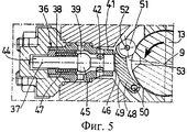
Фиг.5 представляет собой вид, аналогичный фиг.4а, при этом вентиль находится в положении выравнивания давлений, а заглушка находится в закрытом положении.Fig. 5 is a view similar to Fig. 4a, wherein the valve is in the pressure equalization position and the plug is in the closed position.
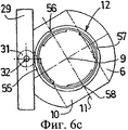
Фиг.6а, 6b и 6с представляют собой виды, аналогичные соответственно фиг.4а, 4b и 4 с, при этом вентиль находится в промежуточном открытом положении.Figures 6a, 6b and 6c are views similar to Figures 4a, 4b and 4c, respectively, with the valve in an intermediate open position.
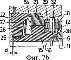
Фиг.7а, 7b и 7с представляют собой виды, аналогичные соответственно фиг.4а, 4b и 4с, при этом вентиль находится в открытом положении.Figures 7a, 7b and 7c are views similar to Figures 4a, 4b and 4c, respectively, with the valve in the open position.
На фиг.1 изображен вентиль 1, содержащий корпус 2, в котором выполнен канал с осью 3. Корпус 2 предусматривает соединение с впускной трубой при помощи выступа 4, расположенного со стороны впуска, а с выпускной трубой - при помощи выступа 5, расположенного со стороны выпуска. Текучая среда, подаваемая по трубам, протекает в направлении, обозначенном стрелкой F, выражения «впускной» и «выпускной» относятся к данному направлению.Figure 1 shows the valve 1, comprising a housing 2, in which a channel with an
Возможны иные варианты исполнения корпуса, в частности, когда корпус присоединяют непосредственно к впускной и выпускной трубам без использования выступов. После этого со стороны верхней части корпуса устанавливают внутренние элементы, а также производят их демонтаж.Other housing variants are possible, in particular when the housing is connected directly to the inlet and outlet pipes without using protrusions. After that, from the side of the upper part of the housing, internal elements are installed, and they are also dismantled.
Кроме того, вентиль 1 имеет поворотную заглушку 6, установленную в корпусе 2 при помощи подшипников 7, 8 таким образом, что заглушка может поворачиваться вокруг оси 9 по существу перпендикулярно оси 3. Заглушка 6 имеет основную сферическую часть, в которой имеется сквозное отверстие 10 с осью 11, расположенной в плоскости, ортогональной оси 9 поворота заглушки 6, и проходящей через ось 3 канала корпуса 2. От основной сферической части заглушки 6 отходят две цилиндрические части 12, оси которых по существу совпадают с осью 9 поворота заглушки 6 и каждая из которых выходит с одной стороны основной сферической части.In addition, the valve 1 has a
Заглушка 6 находится в связи с приводным валом 13, который по существу коаксиален с осью 9 и проходит через корпус 2 при помощи промежуточных сальниковых прокладок 14. Вал 13 переходит в наружный рычаг (не показан), который позволяет пользователю перемещать заглушку 6 между:The
- открытым положением, в котором ось 11 отверстия 10 и ось 3 канала корпуса по существу совпадают, после чего текучая среда может протекать от впуска к выпуску;- an open position in which the
- и закрытым положением, в котором ось 11 отверстия 10 образует с осью 3 канала корпуса угол α, составляющий примерно от 70° до 80°, например 80°. Разумеется, размеры заглушки 6 определены таким образом, чтобы в данном положении текучая среда не могла проходить от впуска к выпуску.- and a closed position in which the
В каждой цилиндрической части 12, отходящей от основной сферической части заглушки 6, выполнены четыре по существу одинаковых паза, расположенных по существу на одинаковом расстоянии от плоскости, которая ортогональна оси 9 поворота заглушки 6 и которая проходит через ось 11 сквозного отверстия 10:In each
- первый паз 55 сдвинут в угловом измерении на угол α, составляющий примерно от 70° до 80°, например на 80°, от оси 11 сквозного отверстия 10 в таком направлении, что, когда заглушка 6 находится в закрытом положении, первый паз 55 ориентирован в направлении впуска;- the
- второй паз 56, расположенный по существу в плоскости, образованной осью 9 поворота заглушки 6 и осью 11 сквозного отверстия 10;- a
- третий паз 57, по существу симметричный первому пазу 55 относительно оси 9 поворота заглушки 6;- the
- четвертый паз 58, по существу симметричный второму пазу 56 относительно оси 9 поворота заглушки 6.- the
К примеру, паз имеет полуцилиндрическую форму с осью, которая по существу параллельна оси 9 поворота заглушки 6. Более того, четыре паза, выполненные в одной из цилиндрических частей 12, и четыре паза, выполненные в другой цилиндрической части 12, по существу симметричны друг другу относительно плоскости, которая ортогональна оси 9 и которая проходит через ось 11 сквозного отверстия 10.For example, the groove has a semi-cylindrical shape with an axis that is essentially parallel to the axis of
Седло 15, имеющее центральный проход 16, установлено по существу коаксиально перед заглушкой 6 в канале корпуса 2 с возможностью поступательного перемещения вдоль оси 3 на ограниченное расстояние.A
Если смотреть от впуска к выпуску, седло 15 имеет первую кольцевую часть 17, вторую кольцевую часть 18 большего наружного диаметра, образующую упорную поверхность, третью кольцевую часть 19 еще большего наружного диаметра и далее четвертую кольцевую часть 20, наружный диаметр которой меньше наружного диаметра третьей кольцевой части 19. Внутренний диаметр указанных кольцевых частей по существу одинаков, поэтому центральный проход 16 по сути цилиндрический.Seen from the inlet to the outlet, the
И, наконец, седло 15 имеет находящуюся ближе всего к выпуску пятую кольцевую часть 59 (образующую уплотняющую поверхность седла 15), наружный диаметр которой меньше наружного диаметра третьей кольцевой части 19 (и по сути равный наружному диаметру четвертой кольцевой части 20), а внутренний диаметр больше наружного диаметра первой кольцевой части 17. Преимущество такого выбора размеров будет объяснено далее.And finally, the
Седло 15 установлено в корпусе 2 при помощи кольцевого направляющего элемента 21, расположенного между третьей кольцевой частью 19 и корпусом 2, и кольцевого закрывающего элемента 22, расположенного между первой кольцевой частью 17 и корпусом 2. Между корпусом 2 и направляющим элементом 21 и между корпусом 2 и закрывающим элементом 22 соответственно расположены уплотнения 23, 24. Более того, между закрывающим элементом 22 и седлом 15 расположены кольца 25, при этом между указанными двумя деталями образуется небольшой радиальный зазор.The
Между закрывающим элементом 22, направляющим элементом 21 и седлом 15 образована расположенная со стороны впуска кольцевая камера 26, которая в ограниченной степени сообщается с центральным проходом 16 седла 15 посредством колец 25 и радиального зазора, упомянутого выше. В камере 26 находится пружинная шайба 27, одной стороной опирающаяся на упорную поверхность, образованную между первой и второй кольцевыми частями 17, 18 седла 15, а другой стороной опирающаяся на упорную поверхность, образованную на закрывающем элементе 22. Таким образом, шайба 27 поджимает седло 15 по направлению к заглушке 6, в результате чего выпускной конец 28 седла 15 прижимается к заглушке 6 и, следовательно, обеспечивает герметичность вентиля 1, когда заглушка 6 находится в закрытом положении. Более того, в камере 26, напротив ее поверхности, расположенной со стороны выпуска, расположена металлическая мембрана 54, один конец которой прикреплен к направляющему элементу 21, а другой конец прикреплен к седлу 15. Мембрана 54 обеспечивает уплотнение между седлом 15 и корпусом 2, когда вентиль находится в закрытом и герметичном положении.Between the
На четвертой кольцевой части 20 седла 15 в канале корпуса 2 установлено кольцо 29. Кольцо 29, изображенное на фиг.2, имеет две диаметрально противоположные, по существу имеющие форму параллелепипеда полости 30, в каждую из которых входит ролик 31 с возможностью вращения вокруг общей оси 32, по существу объединяющей центры двух полостей 30. Кольцо 29 установлено на седле 15 таким образом, что ось 32 по существу параллельна оси 9 поворота заглушки 6 и пересекает ось 3 канала корпуса 2. Таким образом, каждый ролик 31 расположен напротив цилиндрической части 12 заглушки 6, на том же самом осевом уровне, что и пазы 55, 56, 57, 58, и выступает по направлению к заглушке 6 относительно выпускного конца 28 седла 15.A
Более того, чтобы обеспечить плавный переход между центральным проходом 16, отверстием 10 и центральным проходом 34, внутри канала корпуса 2 на расположенной со стороны выпуска стороне заглушки 6 установлено вспомогательное седло 33, расположенное со стороны выпуска и имеющее центральный проход 34 и промежуточное уплотнение 35. Как вариант, вспомогательное седло может иметь конструкцию, схожую с седлом 15, в частности, чтобы использовать вентиль 1 в обоих направлениях протекания текучей среды (направление, обозначенное стрелкой F и противоположное ему направление). В случае двунаправленного вентиля каждое седло, «впускное» и «выпускное», в дополнение к мембране 54 предпочтительно снабжено встречной мембраной, которая включается в действие в фазе выравнивания давлений, защищая мембрану, взаимосвязанную с седлом на выпускной стороне, от воздействия противодавления, которое не могла бы выдержать одна мембрана.Moreover, in order to ensure a smooth transition between the
Когда вентиль 1 находится в открытом положении, поток текучей среды на впуске, центральный проход 16 седла 15, сквозное отверстие 10 заглушки 6, центральный проход 34 седла 33 и поток текучей среды на выпуске по существу коаксиальны и имеют сходные поперечные сечения.When the valve 1 is in the open position, the fluid flow at the inlet, the
Итак, как показано на фиг.1 и 3, вентиль 1 содержит средства, предназначенные для выравнивания давления между впускным концом и выпускным концом седла 15 до того, как вентиль 1 откроется, и эти средства образуют перепускной контур.So, as shown in figures 1 and 3, the valve 1 contains means for balancing the pressure between the inlet end and the outlet end of the
Средства выравнивания давлений включают, во-первых, цилиндрическое проходное приспособление 36 с осью 37, выполненное в корпусе 2 по существу ортогонально оси 9 поворота заглушки 6 и оси 3 канала корпуса 2. Приспособление 36 имеет первую часть 38 с радиальными отверстиями 39, открытыми в канал 40, который высверлен наклонно в корпусе 2, начинаясь от кольцевой камеры 26. Кроме того, приспособление 36 содержит вторую часть 41, которая отходит от первой части 38 в направлении вала 13 и диаметр которой меньше диаметра первой части 38. Вторая часть 41 имеет радиальные отверстия 42, открытые в центральный объем, в котором находится заглушка 6, причем когда вентиль 1 находится в закрытом и герметичном положении, данный объем образует кольцевую камеру 43, расположенную со стороны выпуска между седлом 15 и заглушкой 6 и не сообщающуюся с центральным проходом 16 седла 15.The pressure equalization means include, firstly, a
Внутри приспособления 36 по существу аксиально расположен толкатель 44, имеющий шар 45, диаметр которого достаточен для того, чтобы препятствовать проходу текучей среды между первой частью 38 и второй частью 41 в месте, где сужается поперечное сечение. Толкатель 44 продолжается по другую сторону шара 45, вплоть до своего свободного конца, на котором образована опорная поверхность 46, расположенная напротив вала 13. В проходном приспособлении 36, вокруг толкателя 44, установлена пружина 47. Толкатель 44 может перемещаться поступательно вдоль оси 37 между:Inside the
- запертым положением, по направлению к которому толкатель 44 поджимается пружиной 47. В данном запертом положении шар 45 препятствует проходу текучей среды между частями 38 и 41 приспособления 36, так что текучая среда не может пройти из кольцевой камеры 26 к кольцевой камере 43. Более того, толкатель 44 выступает из приспособления 36 к зоне вала 13, так что опорная поверхность 46 расположена снаружи приспособления 36;- a locked position, towards which the
- и разомкнутым положением, в котором толкатель 44 перемещается в сторону от вала 13. Тогда пружина 47 сжимается и опорная поверхность 46 оказывается вблизи того конца второй части 41, который обращен к валу 13. В данном положении шар 45 больше не препятствует проходу текучей среды между первой частью 38 и второй частью 41 приспособления 36, таким образом камеры 26 и 43 сообщаются между собой.- and an open position in which the
Кроме того, в средства выравнивания давлений входит кулачок 48, образованный криволинейной частью, присоединенной к крышке 60, при этом сама крышка прикреплена к корпусу 2 вентиля 1, при этом выпуклая внешняя поверхность 49 этого кулачка расположена напротив опорной поверхности 46 толкателя 44. Первый конец кулачка 48 прикреплен к крышке 60 с возможностью поворота вокруг оси 50, по существу параллельной оси 9 поворота заглушки 6, а ко второму концу кулачка 48 прикреплен ролик 51 с возможностью поворота вокруг оси 52, по существу параллельной оси 50. Ролик 51 выполнен с возможностью взаимодействия, при закрытом и герметичном положении вентиля 1, с полостью 53, образованной в валу 13. Полость 53 в угловом измерении отстоит от оси 37 приспособления 36 на угол β, составляющий около 20°.In addition, a
Когда вентиль 1 находится в закрытом и герметичном положении (фиг.4а, 4b и 4 с), заглушка 6 расположена таким образом, что ось 11 ее сквозного отверстия 10 составляет с осью 3 канала корпуса 2 угол α, составляющий около 80°. Тогда ролик 31 кольца 29 расположен в первом пазу 55, образованном в заглушке 6 (фиг.4). Таким образом, вследствие воздействия шайбы 27 и давления на впуске седло 15 прижато к заглушке 6 и расстояние d между расположенной со стороны впуска поверхностью закрывающего элемента 22 и расположенной со стороны впуска поверхностью седла является максимальным (фиг.4b). Тот факт, что наружный диаметр пятой кольцевой части 59 седла 15 меньше наружного диаметра третьей кольцевой части 19, дает возможность герметизировать вентиль 1 за счет воздействия давления уплотнения, когда перепуск закрыт.При этом ролик 51 кулачка 48 находится в валу 13 заглушки 6, а толкатель 44 находится в закрытом положении (фиг.4а).When the valve 1 is in the closed and sealed position (Figs. 4a, 4b and 4c), the
Воздействие пользователя на рычаг приводит к повороту вала 13 вокруг оси 9. Начало поворотного движения вала 13 (поворот примерно от 10° до 20°) не приводит к какому-либо повороту заглушки 6 вследствие люфта. Поэтому заглушка 6 остается в закрытом положении, как на фиг.4с. Однако следствием данного поворота является то, что ролик 51 кулачка 48 покидает полость 53 (фиг.5). Таким образом, кулачок 48 поворачивается вокруг оси 50, заставляя толкатель 44 отодвигаться от вала 13, тем самым освобождая проход между первой и второй частями 38, 41 проходного приспособления 36. Теперь текучая среда может протекать из кольцевой камеры 26 к кольцевой камере 43. Таким образом, посредством перепускного контура возникает выравнивание давлений на обеих сторонах седла 15. Следовательно, теперь седло 15 проталкивается по направлению к заглушке 6 только за счет действия шайбы 27. Вентиль 1 находится в положении выравнивания давлений, а заглушка 6 находится все еще в закрытом положении. Однако, поскольку внутренний диаметр пятой кольцевой части 59 седла 15 больше наружного диаметра первой кольцевой части 17, возникает сила, которая направлена противоположно силе, оказываемой шайбой 27, и действие которой заключается в уменьшении или даже в исключении воздействия указанной шайбы 27 и, следовательно, в уменьшении трения в процессе открытия вентиля 1.The impact of the user on the lever leads to the rotation of the
Дальнейший поворот рычага и, следовательно, вала 13 заставляет заглушку 6 поворачиваться, при этом отсутствует сила тяги, оказываемая седлом 15 вследствие давления на впуске. Когда заглушка 6 поворачивается вокруг оси 9, ролик 31 кольца 29 покидает первый паз 55 и катится по боковой поверхности цилиндрической части 12 заглушки 6. За этим следует движение обратного хода седла 15 относительно оси 9, противодействуя силе, оказываемой шайбой 27. При этом расстояние d между расположенной со стороны впуска поверхностью закрывающего элемента 22 и расположенной со стороны впуска поверхностью седла является минимальным. Таким образом, поворот заглушки 6 облегчается благодаря тому факту, что трение относительно седла 15 гораздо меньше, поскольку оно локализовано только в ролике 31, а не по всей контактной площади между седлом 15 и сферической частью заглушки 6. Вентиль 1 находится в промежуточном открытом положении (фиг.6а, 6b и 6с).Further rotation of the lever and, therefore, the
В открытом положении (фиг.7а, фиг.7b, фиг.7с) ролик 31 кольца 29 находится во втором пазу 56, таким образом седло 15 снова устремляется по направлению к заглушке 6 и давит на нее (расстояние d максимально). Угол поворота заглушки 6 ограничен значениями между 70° и 80°, так что общий поворот рычага остается равным 90°: таким образом, изобретение может использоваться со стандартными приводами (пневматическими, электрическими или гидравлическими). Перепускной контур все еще открыт.In the open position (Fig. 7a, Fig. 7b, Fig. 7c), the
Когда вал 13 приводится в движение в направлении запирания, сначала компенсируется люфт, а затем заглушка 6 поворачивается вокруг оси 9, при этом перепускной контур все еще открыт. Когда заглушка 6 возвращается в полностью закрытое положение, одновременно с окончанием поворота вала 13 ролик 31 кольца 29 входит в первый паз 55 (расстояние d максимально), а ролик 51 кулачка 48 входит в полость 53. Толкатель 44 под воздействием пружины 47 перемещается поступательно по направлению к валу 13. Затем шар 45 перекрывает проход между кольцевой камерой 26 и кольцевой камерой 43. Тогда разность давлений между впускным и выпускным концами седла 15 обеспечивает поджатие седла 15 к заглушке 6.When the
Таким образом, изобретение привносит очевидное усовершенствование по сравнению с известным уровнем техники путем создания вентиля, который полностью герметичен при низком или среднем давлении и который прост в эксплуатации.Thus, the invention brings an obvious improvement over the prior art by creating a valve that is completely tight at low or medium pressure and which is easy to operate.
Само собой разумеется, что изобретение не ограничено вариантом выполнения, который описан выше путем примера, а, напротив, охватывает все разновидности его вариантов выполнения.It goes without saying that the invention is not limited to the embodiment described above by way of example, but rather encompasses all variations of its embodiments.
Claims (10)
- корпус (2), в котором выполнен канал с осью (3) и который предназначен для размещения между впускной трубой и выпускной трубой;
- по существу, сферическую поворотную заглушку (6), установленную в корпусе (2) с возможностью поворота между закрытым положением и открытым положением вокруг оси (9), по существу, перпендикулярной оси (3) канала, и имеющую сквозное отверстие (10) с осью (11), которое при нахождении заглушки в открытом положении обеспечивает проход текучей среды из впускной трубы к выпускной трубе;
- седло (15), расположенное со стороны впуска, имеющее центральный проход (16) и установленное в канале корпуса (2) перед заглушкой (6) с возможностью поступательного перемещения вдоль оси (3) указанного канала;
- средства выравнивания давления текучей среды между впускным и выпускным концами седла (15) перед открытием вентиля (1);
- упругое средство (27), предназначенное для поджатия указанного седла (15) к заглушке (6);
отличающийся тем, что он дополнительно содержит:
- по меньшей мере один выступ, выполненный на седле (15) и выступающий, по существу, параллельно оси (3) канала корпуса (2) в направлении заглушки (6), и по меньшей мере один первый паз (55, 56), выполненный в заглушке (6) и предназначенный для взаимодействия с выступом при нахождении заглушки (6) в закрытом положении;
- второй паз (56), выполненный в заглушке (6) с возможностью взаимодействия с выступом при нахождении заглушки (6) в открытом положении и расположенный, по существу, на таком же расстоянии, что и первый паз (55), от плоскости, которая ортогональна оси (9) поворота заглушки (6) и которая проходит через ось (11) сквозного отверстия (10), причем указанный второй паз (56) расположен, по существу, в плоскости, образованной осью (9) поворота заглушки (6) и осью (11) сквозного отверстия (10) заглушки (6), при этом первый паз (55) в угловом измерении отстоит от второго паза (56) на угол (α), составляющий от 70 до 80°.1. A valve comprising:
- a housing (2) in which a channel with an axis (3) is made and which is intended to be placed between the inlet pipe and the exhaust pipe;
- essentially a spherical rotary plug (6) mounted in the housing (2) with the possibility of rotation between the closed position and the open position around the axis (9), essentially perpendicular to the axis (3) of the channel, and having a through hole (10) with an axis (11), which, when the plug is in the open position, allows the passage of fluid from the inlet pipe to the exhaust pipe;
- a saddle (15) located on the inlet side, having a central passage (16) and installed in the channel of the housing (2) before the plug (6) with the possibility of translational movement along the axis (3) of the specified channel;
- means for balancing the fluid pressure between the inlet and outlet ends of the seat (15) before opening the valve (1);
- elastic means (27), designed to tighten the specified saddle (15) to the plug (6);
characterized in that it further comprises:
- at least one protrusion made on the saddle (15) and protruding essentially parallel to the axis (3) of the channel of the housing (2) in the direction of the plug (6), and at least one first groove (55, 56) made in the plug (6) and designed to interact with the protrusion when the plug (6) is in the closed position;
- a second groove (56) made in the plug (6) with the possibility of interaction with the protrusion when the plug (6) is in the open position and located essentially at the same distance as the first groove (55) from the plane orthogonal to the axis (9) of rotation of the plug (6) and which passes through the axis (11) of the through hole (10), and the specified second groove (56) is located essentially in the plane formed by the axis of rotation (9) of the plug (6) and the axis (11) of the through hole (10) of the plug (6), while the first groove (55) in the angular measurement is separated from the second groove (56) and the angle (α), of from 70 to 80 °.
- седло (15) прижато к заглушке (6) с обеспечением, таким образом, герметичности вентиля (1), когда средства выравнивания давлений находятся в закрытом положении;
- на седло (15) действует сила тяги, противодействующая упругому средству (27), когда средства выравнивания давлений находятся в открытом положении.7. The valve according to claim 1, characterized in that the seat (15) has annular parts (17, 18, 19, 20, 59) that follow one after another in the direction from the inlet end to the outlet end and the dimensions of which are selected in this way that due to the pressure of the fluid at the inlet and outlet of the saddle (15):
- the seat (15) is pressed against the plug (6), thus ensuring the tightness of the valve (1) when the pressure equalization means are in the closed position;
- a thrust force acting on the seat (15) counteracts the elastic means (27) when the pressure equalization means are in the open position.
- расположенную со стороны впуска кольцевую камеру (26), стенка которой, расположенная со стороны выпуска, образована выступом, выполненным на седле (15) и обращенным к впуску;
- расположенную со стороны выпуска кольцевую камеру (43), которая расположена между седлом (15) и заглушкой (6) и которая не сообщается с центральным проходом (16) седла (15), когда вентиль (1) находится в закрытом и герметичном положении;
- проходное приспособление (36) с осью (37), выполненное в корпусе (2) и имеющее первую часть (38), которая соединена каналом (40) с кольцевой камерой (26), расположенной со стороны впуска, и вторую часть (41), которая сообщается с кольцевой камерой (43), расположенной со стороны выпуска;
- средство (44, 45), предназначенное для перекрытия прохода между первой и второй частями (38, 41) проходного приспособления (36) и расположенное в указанном приспособлении с возможностью поступательного перемещения вдоль его оси (37), при этом указанное перекрывающее средство поджато упругим средством (47) по направлению к положению, в котором оно закрывает указанный проход, и имеет опорную поверхность (46), которая в указанном положении расположена снаружи проходного приспособления (36) в зоне его второй части (41);
- кулачок (48), расположенный в корпусе (2) между указанным перекрывающим средством и валом (13), инициирующим поворотное движение заглушки (6) и, по существу, коаксиальным с осью (9) ее поворота, и выполненный с возможностью взаимодействия с указанной опорной поверхностью (46) при повороте указанного приводного вала (13) и, таким образом, приведения в движение перекрывающего средства в проходном приспособлении (36) по направлению к положению освобождения прохода между первой и второй частями (38, 41) проходного приспособления (36), противодействуя силе, оказываемой упругим средством (47), а также давлению.8. The valve according to one of claims 1 to 7, characterized in that the means for balancing the pressure contain:
- located on the inlet side of the annular chamber (26), the wall of which, located on the outlet side, is formed by a protrusion made on the saddle (15) and facing the inlet;
- an annular chamber (43) located on the exhaust side, which is located between the seat (15) and the plug (6) and which does not communicate with the central passage (16) of the seat (15) when the valve (1) is in a closed and sealed position;
- a passage device (36) with an axis (37) made in the housing (2) and having a first part (38), which is connected by a channel (40) with an annular chamber (26) located on the inlet side, and a second part (41) which communicates with the annular chamber (43) located on the exhaust side;
- means (44, 45), designed to block the passage between the first and second parts (38, 41) of the passage device (36) and located in the specified device with the possibility of translational movement along its axis (37), while the said overlapping means is elastic means (47) towards the position in which it closes said passage and has a supporting surface (46) which, in the indicated position, is located outside the passage fixture (36) in the region of its second part (41);
- a cam (48) located in the housing (2) between the specified overlapping means and the shaft (13), initiating a rotational movement of the plug (6) and essentially coaxial with the axis (9) of its rotation, and made with the possibility of interaction with the specified the supporting surface (46) when turning the specified drive shaft (13) and, thus, driving the overlapping means in the passage device (36) in the direction of the release position of the passage between the first and second parts (38, 41) of the passage device (36) counteracting force, oh shown by elastic means (47), as well as pressure.
Applications Claiming Priority (2)
| Application Number | Priority Date | Filing Date | Title |
|---|---|---|---|
| FR0509949A FR2891341B1 (en) | 2005-09-29 | 2005-09-29 | SPHERICAL ROTATING SHUTTER VALVE |
| FR0509949 | 2005-09-29 |
Publications (2)
| Publication Number | Publication Date |
|---|---|
| RU2008110698A RU2008110698A (en) | 2009-11-10 |
| RU2417336C2 true RU2417336C2 (en) | 2011-04-27 |
Family
ID=36588780
Family Applications (1)
| Application Number | Title | Priority Date | Filing Date |
|---|---|---|---|
| RU2008110698/06A RU2417336C2 (en) | 2005-09-29 | 2006-09-25 | Valve with spherical rotary plug |
Country Status (10)
| Country | Link |
|---|---|
| US (1) | US8167267B2 (en) |
| EP (1) | EP1938010B1 (en) |
| CN (1) | CN101273225B (en) |
| AT (1) | ATE477443T1 (en) |
| DE (1) | DE602006016148D1 (en) |
| FR (1) | FR2891341B1 (en) |
| PL (1) | PL1938010T3 (en) |
| RU (1) | RU2417336C2 (en) |
| WO (1) | WO2007036629A1 (en) |
| ZA (1) | ZA200802052B (en) |
Cited By (2)
| Publication number | Priority date | Publication date | Assignee | Title |
|---|---|---|---|---|
| RU2629317C2 (en) * | 2015-12-09 | 2017-08-28 | Акционерное общество "Опытное Конструкторское Бюро Машиностроения имени И.И. Африкантова" (АО "ОКБМ Африкантов") | Method of assembly of the steering of the ball valve in the body |
| RU2734989C2 (en) * | 2019-04-22 | 2020-10-27 | Акционерное общество "Опытное Конструкторское Бюро Машиностроения имени И.И. Африкантова" (АО "ОКБМ Африкантов") | Ball valve |
Families Citing this family (1)
| Publication number | Priority date | Publication date | Assignee | Title |
|---|---|---|---|---|
| WO2021101805A1 (en) * | 2019-11-21 | 2021-05-27 | Consolidated Foam | Liquid flow regulation device |
Family Cites Families (16)
| Publication number | Priority date | Publication date | Assignee | Title |
|---|---|---|---|---|
| US3047265A (en) * | 1958-08-11 | 1962-07-31 | Kaiser Rudolf | Spherical-plug cock having a pistontype packing ring displaceably mounted at one side of the cock body |
| US3565392A (en) * | 1969-04-28 | 1971-02-23 | Grove Valve & Regulator Co | Flow-blocking device with retractable sealing means |
| US3737145A (en) * | 1971-08-02 | 1973-06-05 | Walworth Co | Fabricated valve ball |
| CS157817B1 (en) * | 1972-11-01 | 1974-10-15 | ||
| AU1914976A (en) * | 1975-11-10 | 1978-05-04 | Itt | Valve seal |
| US5338003A (en) * | 1983-11-14 | 1994-08-16 | John Beson | Dual seal ball valve |
| FR2564558B1 (en) * | 1984-05-18 | 1986-10-03 | Vanatome | SPHERICAL ROTATING BALL VALVE |
| JPS6415575A (en) * | 1987-07-07 | 1989-01-19 | Kubota Ltd | Ball valve |
| DE3824919A1 (en) * | 1987-08-14 | 1989-02-23 | Gen Electric | Ball valve |
| JPH01169179A (en) * | 1987-12-22 | 1989-07-04 | Babcock Hitachi Kk | Non-sliding three-way valve |
| FR2646488B1 (en) * | 1989-04-28 | 1991-07-26 | Vanatome | SPHERICAL ROTARY TAP |
| JPH0384269A (en) * | 1989-08-28 | 1991-04-09 | Kurimoto Ltd | Starting mechanism for spherical valve |
| CA1318905C (en) * | 1989-10-10 | 1993-06-08 | John Steele | Ball valves for pipelines |
| CN2073058U (en) * | 1990-08-18 | 1991-03-13 | 天津大学 | Adjustable compensating sealing ball valve |
| CN1073247A (en) * | 1991-12-14 | 1993-06-16 | 中国人民解放军后勤工程学院 | Swing ball low torque ball valve |
| US6966537B2 (en) * | 2003-03-11 | 2005-11-22 | Worldwide Oilfield Machine, Inc. | Valve with seat assembly |
-
2005
- 2005-09-29 FR FR0509949A patent/FR2891341B1/en active Active
-
2006
- 2006-09-25 US US12/088,801 patent/US8167267B2/en active Active
- 2006-09-25 CN CN2006800351779A patent/CN101273225B/en active Active
- 2006-09-25 PL PL06808198T patent/PL1938010T3/en unknown
- 2006-09-25 EP EP06808198A patent/EP1938010B1/en active Active
- 2006-09-25 RU RU2008110698/06A patent/RU2417336C2/en active
- 2006-09-25 WO PCT/FR2006/002182 patent/WO2007036629A1/en active Application Filing
- 2006-09-25 DE DE602006016148T patent/DE602006016148D1/de active Active
- 2006-09-25 AT AT06808198T patent/ATE477443T1/en not_active IP Right Cessation
-
2008
- 2008-03-04 ZA ZA200802052A patent/ZA200802052B/en unknown
Cited By (2)
| Publication number | Priority date | Publication date | Assignee | Title |
|---|---|---|---|---|
| RU2629317C2 (en) * | 2015-12-09 | 2017-08-28 | Акционерное общество "Опытное Конструкторское Бюро Машиностроения имени И.И. Африкантова" (АО "ОКБМ Африкантов") | Method of assembly of the steering of the ball valve in the body |
| RU2734989C2 (en) * | 2019-04-22 | 2020-10-27 | Акционерное общество "Опытное Конструкторское Бюро Машиностроения имени И.И. Африкантова" (АО "ОКБМ Африкантов") | Ball valve |
Also Published As
| Publication number | Publication date |
|---|---|
| ATE477443T1 (en) | 2010-08-15 |
| EP1938010B1 (en) | 2010-08-11 |
| US8167267B2 (en) | 2012-05-01 |
| DE602006016148D1 (en) | 2010-09-23 |
| CN101273225A (en) | 2008-09-24 |
| WO2007036629A1 (en) | 2007-04-05 |
| RU2008110698A (en) | 2009-11-10 |
| FR2891341A1 (en) | 2007-03-30 |
| PL1938010T3 (en) | 2011-06-30 |
| FR2891341B1 (en) | 2011-04-22 |
| EP1938010A1 (en) | 2008-07-02 |
| ZA200802052B (en) | 2009-02-25 |
| US20090050833A1 (en) | 2009-02-26 |
| CN101273225B (en) | 2010-12-01 |
Similar Documents
| Publication | Publication Date | Title |
|---|---|---|
| US8490945B2 (en) | Valve sealing arrangements and methods | |
| AU2016277653B2 (en) | Hemi-wedge verifiable shutoff valve | |
| WO2013105378A1 (en) | Valve device | |
| US11118737B2 (en) | Compact gas cylinder valve with residual pressure function | |
| CA2604947A1 (en) | Fluid flow control valve with composition seal | |
| US20060118750A1 (en) | Flexible backseat seal for gate valve | |
| RU2417336C2 (en) | Valve with spherical rotary plug | |
| RU2618634C1 (en) | Ball cock | |
| US3929316A (en) | Non-floating seat structure for expanding gate valves | |
| JPS6119871B2 (en) | ||
| JP6367078B2 (en) | Water stop structure of butterfly valve | |
| KR200334648Y1 (en) | Segment plug type double eccentric metal seat ball valve | |
| KR101741482B1 (en) | Floating-type ball valve with operation-relief structure in the closed state | |
| KR100613882B1 (en) | Butterfly valve | |
| KR101467141B1 (en) | Watertight structur of shaft housing in butterfly valve | |
| RU2312264C2 (en) | Valve, particularly, valve for radiators | |
| KR100334123B1 (en) | Double interception and open device for ball valve | |
| RU2326279C1 (en) | Valve | |
| KR101851753B1 (en) | Safety ball valve | |
| KR200338623Y1 (en) | Double side segment plug type metal seat ball valve | |
| JP4146848B2 (en) | Valve device | |
| JP2003240133A (en) | Ball valve and fluid supply system using the same | |
| KR200356872Y1 (en) | Butterfly valve | |
| RU2068520C1 (en) | Hydraulic valve | |
| KR200283573Y1 (en) | Ball check valve |
Legal Events
| Date | Code | Title | Description |
|---|---|---|---|
| PC43 | Official registration of the transfer of the exclusive right without contract for inventions |
Effective date: 20151230 |