RU2415503C1 - Clicking fixture to fix body - Google Patents
Clicking fixture to fix body Download PDFInfo
- Publication number
- RU2415503C1 RU2415503C1 RU2009140144/09A RU2009140144A RU2415503C1 RU 2415503 C1 RU2415503 C1 RU 2415503C1 RU 2009140144/09 A RU2009140144/09 A RU 2009140144/09A RU 2009140144 A RU2009140144 A RU 2009140144A RU 2415503 C1 RU2415503 C1 RU 2415503C1
- Authority
- RU
- Russia
- Prior art keywords
- slider
- slide
- row
- housing
- mount according
- Prior art date
Links
- 230000000903 blocking effect Effects 0.000 claims abstract description 9
- 230000000694 effects Effects 0.000 claims abstract description 4
- 239000000463 material Substances 0.000 claims description 7
- 229920003023 plastic Polymers 0.000 claims description 3
- 239000004033 plastic Substances 0.000 claims description 3
- 230000003993 interaction Effects 0.000 claims description 2
- 239000007769 metal material Substances 0.000 claims description 2
- 238000000034 method Methods 0.000 abstract description 2
- 238000010276 construction Methods 0.000 abstract 1
- 239000000126 substance Substances 0.000 abstract 1
- 239000004020 conductor Substances 0.000 description 4
- 230000006870 function Effects 0.000 description 4
- 238000009434 installation Methods 0.000 description 4
- 230000006835 compression Effects 0.000 description 3
- 238000007906 compression Methods 0.000 description 3
- 230000009471 action Effects 0.000 description 2
- 230000008859 change Effects 0.000 description 2
- 230000010354 integration Effects 0.000 description 2
- 230000003446 memory effect Effects 0.000 description 2
- 238000004519 manufacturing process Methods 0.000 description 1
- 230000007246 mechanism Effects 0.000 description 1
Images
Classifications
-
- H—ELECTRICITY
- H02—GENERATION; CONVERSION OR DISTRIBUTION OF ELECTRIC POWER
- H02B—BOARDS, SUBSTATIONS OR SWITCHING ARRANGEMENTS FOR THE SUPPLY OR DISTRIBUTION OF ELECTRIC POWER
- H02B1/00—Frameworks, boards, panels, desks, casings; Details of substations or switching arrangements
- H02B1/015—Boards, panels, desks; Parts thereof or accessories therefor
- H02B1/04—Mounting thereon of switches or of other devices in general, the switch or device having, or being without, casing
- H02B1/052—Mounting on rails
- H02B1/0526—Mounting on rails locking or releasing devices actuated from the front face of the apparatus
-
- H—ELECTRICITY
- H02—GENERATION; CONVERSION OR DISTRIBUTION OF ELECTRIC POWER
- H02B—BOARDS, SUBSTATIONS OR SWITCHING ARRANGEMENTS FOR THE SUPPLY OR DISTRIBUTION OF ELECTRIC POWER
- H02B1/00—Frameworks, boards, panels, desks, casings; Details of substations or switching arrangements
- H02B1/20—Bus-bar or other wiring layouts, e.g. in cubicles, in switchyards
- H02B1/205—Bus-bar or other wiring layouts, e.g. in cubicles, in switchyards for connecting electrical apparatus mounted side by side on a rail
Landscapes
- Engineering & Computer Science (AREA)
- Power Engineering (AREA)
- Mounting Components In General For Electric Apparatus (AREA)
- Buckles (AREA)
- Connections Arranged To Contact A Plurality Of Conductors (AREA)
Abstract
Description
Изобретение касается защелкивающегося крепления для крепления корпуса на направляющей с ползуном, причем ползун содержит исполнительный элемент, блокировочный элемент и область соединения между исполнительным элементом и блокировочным элементом для отклонения направления приводной силы, которая через область соединения воздействует на блокировочный элемент. Кроме того, изобретение касается модуля с такого рода защелкивающимся креплением.The invention relates to a snap fastening for mounting the housing on a slide rail, the slider comprising an actuating element, a locking element and a connection region between the actuating element and the locking element for deflecting a driving force that acts on the locking element through the connecting region. In addition, the invention relates to a module with this kind of snap fastening.
Такого рода защелкивающееся крепление используется в совокупности со встраиваемыми в ряд устройствами, в частности с выключателями из соединений сборных шин. При этом встраиваемое в ряд устройство содержит корпус, который имеет предпочтительную форму для соединения сборных шин. С одной стороны, из соображений имеющегося в наличии пространства, концентрация встраиваемых в ряд устройств поддерживается за счет того, что корпус встраиваемого в ряд устройства, который выполнен, например, в качестве выключателя или защитного автомата, допускает плоскостное расположение других корпусов на двух или более сторонах и одновременно содержит защелкивающееся крепление, которое предусмотрено для крепления корпуса на шине, в частности несущей U-образной шине.This kind of snap fastening is used in conjunction with a number of devices which are built in a row, in particular with switches from busbar connections. In this case, the row-mounted device comprises a housing which has a preferred shape for connecting busbars. On the one hand, for reasons of available space, the concentration of row-mounted devices is maintained due to the fact that the case of a row-mounted device, which is designed, for example, as a switch or a circuit breaker, allows the planar arrangement of other cases on two or more sides and at the same time comprises a snap fastener which is provided for fastening the housing to the tire, in particular to the supporting U-shaped tire.
Такой выключатель или защитный автомат фиксируется на несущей U-образной шине с помощью ползуна. При этом проблематично, что несущая U-образная шина при использовании выключателя расположена на обращенной от пользователя стороне и отсоединение соединения сборных шин является трудно реализуемыми вследствие недостаточной доступности в результате расположенных пространственно рядом друг с другом выключателей.Such a switch or circuit breaker is fixed to the U-shaped carrier rail using a slider. It is problematic that the carrier U-bus when using the switch is located on the side away from the user and disconnecting the busbar connection is difficult due to insufficient accessibility as a result of switches located spatially adjacent to each other.
Следовательно, обычные ползуны содержат исполнительный элемент, который постоянно доступен пользователю также в смонтированном состоянии, и содержат, кроме того, блокировочный элемент, который расположен на задней стороне корпуса вблизи шины. Оба элемента соединены посредством области соединения. Задача области соединения заключается в том, чтобы отклонять приводную силу, которая оказывается пользователем на исполнительный элемент, по линии движения блокировочного элемента.Consequently, conventional sliders comprise an actuating element which is always accessible to the user also in the mounted state, and furthermore comprise an interlocking element which is located on the rear side of the housing near the tire. Both elements are connected through the connection area. The task of the connection area is to deflect the driving force that is exerted by the user on the actuating element along the movement line of the locking element.
Одновременно должны быть обеспечены комфортные методы монтажа или демонтажа выключателя. Так, при защелкивании выключателя на шине блокировочный элемент должен иметь возможность под воздействием шины кратковременно перемещаться против направления блокировки. Для демонтажа исполнительный элемент должен иметь возможность перемещения от выключателя в направлении пользователя, причем деблокирование осуществляется за счет соответствующего перемещения блокировочного элемента.At the same time, comfortable methods for mounting or dismounting the circuit breaker should be provided. So, when the switch is snapped onto the bus, the locking element must be able to move briefly against the direction of blocking under the influence of the bus. For dismantling, the actuating element must be able to move from the switch in the direction of the user, and the unlocking is carried out due to the corresponding movement of the locking element.
Вследствие дорогостоящей формы ползуна в прошлом использовались дорогостоящие, состоящие из нескольких частей ползуны.Owing to the costly shape of the slide, costly multi-piece sliders have been used in the past.
Из заявки DE 29710310 U1 известен состоящий из нескольких частей ползун, который подразделяется на блокирующую и отдельную, приводимую в действие часть.From the application DE 29710310 U1, a multi-part slider is known, which is divided into a blocking and a separate, actuated part.
Кроме того, из заявки DE 10243383 B3 известно крепежное устройство для крепления инсталлируемого устройства на несущей шине. Оно содержит на нижней крепежной стороне инсталлируемого устройства ползун, который может перемещаться перпендикулярно несущей шине и в позиции крепления с помощью силы пружины вдавливается в направлении несущей шины, причем фиксирующие выступы ползуна входят в зацепление снизу с несущей шиной. Кроме того, крепежное устройство содержит крепежный рычаг, который по меньшей мере обладает незначительной подвижностью относительно корпуса инсталлируемого устройства и предусмотрен на корпусе с целью фиксации ползуна.In addition, from the application DE 10243383 B3, a fastening device is known for mounting the device to be mounted on a support rail. It contains on the lower mounting side of the device to be installed a slider that can be moved perpendicular to the support rail and in the attachment position is pressed by the force of the spring in the direction of the support rail, the locking tabs of the slide engaging from below with the support rail. In addition, the mounting device includes a mounting lever, which at least has slight mobility relative to the housing of the installed device and is provided on the housing to fix the slide.
Таким же образом из заявки EP 1460720 А известно защелкивающееся на несущей шине устройство, которое содержит нагруженный пружиной ползун с фиксирующими выступами, которые захватывают несущую шину снизу с целью фиксации устройства. С помощью пленочного шарнира ползун соединен с поводком, над которым на исполнительном элементе сформован следующий пленочный шарнир.In the same way, from EP 1460720 A, there is known a snap-in device which comprises a spring-loaded slider with locking protrusions which grasp the support tire from below in order to fix the device. Using a film hinge, the slider is connected to a leash over which the next film hinge is formed on the actuator.
Далее, из заявки DE 19709811 A1 известно устройство для крепления устройства на несущей шине, которое содержит два удерживающих ползуна, которые в положении удерживания захватывают снизу края несущей шины. Один орган управления соединен с удерживающими ползунами с помощью механизма отклонения силы, который содержит несколько отлитых пленочных шарниров. С помощью возвратных пружин вырабатывается восстанавливающая сила, которая оттесняет удерживающие ползуны в положение удерживания.Further, from DE 19709811 A1, there is known a device for mounting a device on a support rail, which comprises two holding sliders which, in the holding position, grab the edges of the support rail from below. One control is connected to the holding sliders by a force deflection mechanism that comprises several cast film hinges. With the help of return springs, a restoring force is generated, which pushes the holding sliders into the holding position.
Задачей изобретения является предложение защелкиваемого крепления для модулей, в частности встраиваемых в ряд устройств и аналогичных устройств, которые могут удобным образом, с возможностью удобного разъединения и с низкими затратами изготавливаться также при подключенных проводниках или сборных шинах также из расположенной в ряд структуры.The objective of the invention is to provide a snap fastening for modules, in particular built-in a number of devices and similar devices, which can be conveniently, with the possibility of convenient disconnection and low cost to be made also with connected conductors or busbars from a row structure.
Эта задача решается при защелкивающемся креплении названного выше типа за счет того, что ползун выполнен в качестве монолитного элемента и по меньшей мере его область соединения выполнена упругой с возвратом в исходное положение. Кроме того, задача решается с помощью модуля с такого рода защелкивающимся креплением.This problem is solved with a snap fastening of the type mentioned above due to the fact that the slider is made as a monolithic element and at least its connection area is made elastic with a return to its original position. In addition, the problem is solved with the help of a module with this kind of snap fastening.
В соответствии с изобретением ползун защелкивающегося крепления выполнен в форме монолитного соединения, в результате чего исполнительный элемент и блокировочный элемент соединены между собой не только с геометрическим замыканием, но и с замыканием по материалу, то есть ползун не должен разбираться на свои составные части без возможности их повреждения. Соединение обоих элементов реализуется при этом с помощью области соединения, которая выполнена упруго возвратной. По мере необходимости также и исполнительный и блокирующий элемент могут обладать функцией упругого возвращения. В положении блокировки защелкивающегося соединения ползун находится в форме, которая соответствует форме, которую он имел бы в качестве разъединенной детали. Действие силы, упруго возвращающей в исходное положение в первоначальную форму, образуется во взаимодействии ползуна с его направляющей, которая состоит, например, из частей корпуса или составных частей защелкивающегося крепления. Вследствие любой, например эллиптической, круглой или аналогичной, формы области соединения или соответствующей формы направляющей ползуна, перемещение ползуна за счет приведения в действие исполнительного элемента или за счет обусловленного шиной приведения в действие блокировочного элемента обуславливает принудительную деформацию ползуна, который вследствие своих свойств эффекта запоминания формы отжимается назад в позицию блокировки. Иными словами, деформация области соединения всегда ведет к развитию упругого усилия пружины, которое отжимает ползун назад в позицию блокировки.In accordance with the invention, the snap fastening slider is made in the form of a monolithic connection, as a result of which the actuating element and the locking element are interconnected not only with a geometric closure, but also with a material closure, that is, the slider must not be disassembled into its components without the possibility of them damage. The connection of both elements is realized with the help of the connection region, which is made elastically returnable. As necessary, the actuator and the blocking element may also have an elastic return function. In the locked position of the snap connection, the slider is in a shape that matches the shape that it would have as a disconnected part. The action of a force elastically returning to its original position in its original form is formed in the interaction of the slider with its guide, which consists, for example, of body parts or components of a snap fastening. Due to any, for example, elliptical, round or similar, shape of the connection region or the corresponding shape of the slide guide, the movement of the slide due to the actuation of the actuator or due to the actuation of the locking element caused by the tire causes the slider to deform, which, due to its shape-memory effect, pushes back to the lock position. In other words, deformation of the joint area always leads to the development of elastic spring force, which pushes the slider back to the lock position.
При предпочтительной форме выполнения ползун состоит из неметаллического материала, в частности пластмассы. Основополагающее значение имеет свойство эффекта запоминания формы, которое, например за счет использования специальных пластмасс, может преобразовываться также эффективным в стоимостном отношении образом. Тем самым ползун с функцией изменения направления силы, одновременно сочетает функцию возврата в исходное положение вследствие собственной упругости или эффекта запоминания формы.In a preferred embodiment, the slider consists of a non-metallic material, in particular plastic. Of fundamental importance is the property of the shape memory effect, which, for example, through the use of special plastics, can also be transformed in a cost-effective manner. Thus, the slider with the function of changing the direction of the force simultaneously combines the function of returning to the initial position due to intrinsic elasticity or the effect of shape memorization.
Предпочтительным образом защелкивающееся крепление содержит направляющую ползуна, которая согласована с формой ползуна. В положении блокировки форма, которая задана для ползуна направляющей, точно соответствует форме, в которой ползун вырабатывает наименьшие (с предварительным натяжением) или не вырабатывает (без предварительного натяжения) силы упругости. В этой взаимосвязи важным является то, что за счет высокой кривизны направляющей может быть выработана высокая упругая сила, которая, однако, одновременно предполагает соответствующим образом высокую стабильность материала ползуна. Осуществляется обдумывание аспектов, касающихся стабильности материала и необходимой крутизны. За счет этого по мере необходимости могут достигаться высокие возвращающие силы, которые одновременно требуют высокой стабильности материала ползуна.In a preferred manner, the snap fastener comprises a slide guide that is aligned with the shape of the slide. In the locked position, the shape that is set for the guide slider exactly matches the shape in which the slider produces the least (with pre-tension) or does not (without pre-tension) elasticity. In this relationship, it is important that due to the high curvature of the guide, a high elastic force can be generated, which, however, at the same time assumes a correspondingly high stability of the slide material. Consideration is being given to aspects related to the stability of the material and the necessary steepness. Due to this, as necessary, high restoring forces can be achieved, which at the same time require high stability of the slide material.
Предпочтительным образом направляющая ползуна встроена по меньшей мере частично в корпус. Корпус модуля, устройства для встраивания в ряд или выключателя, как правило, не является обязательным, в результате чего при дополнительном приеме свойств направляющей возможна экономия на конструктивных элементах или материале. К тому же введение защелкивающегося крепления облегчает расположение вблизи ограничительных поверхностей того или иного устройства. Тем самым по мере надобности снимается принуждение к искривлению ползуна.Preferably, the slide guide is integrated at least partially into the housing. The housing of a module, a device for mounting in a row or a switch, as a rule, is not mandatory, as a result of which, with the additional reception of the properties of the guide, savings on structural elements or material are possible. In addition, the introduction of snap fastening facilitates the location near the bounding surfaces of a device. Thus, as necessary, the coercion to bend the slider is removed.
Предпочтительным образом ползун, в частности в его области соединения, содержит одно или несколько отверстий для проведения контактирующих элементов, например проводников или кабелей. Тем самым предпочтительно поддерживается расположение ползуна в корпусе контура, причем одновременно область соединения может изменяться в соответствии с требованиями. Так, например, могут предусматриваться несколько отверстий или реализовываться определенная форма отверстий, так как меньшие затраты приходятся на форму соединительной области и значительно большие затраты приходятся на его функцию передачи силы и его упругость.Preferably, the slider, in particular in its connection area, contains one or more holes for conducting contacting elements, such as conductors or cables. Thereby, the arrangement of the slider in the loop housing is preferably supported, wherein at the same time the connection area can be changed in accordance with the requirements. So, for example, several holes can be provided or a certain shape of holes can be realized, since lower costs fall on the shape of the connecting region and significantly higher costs fall on its function of transmitting force and its elasticity.
Предпочтительным образом в случае предпочтительной формы выполнения защелкивающееся соединение может быть встроено, например, в модуль, устройство для встраивания в ряд или выключатель, и при этом оно может быть выполнено для таких шин, как, например, сборная шина или U-образная шина.Advantageously, in the case of the preferred embodiment, the snap connection can be integrated, for example, into a module, an in-line device or a switch, and in this case it can also be implemented for such tires as, for example, a bus bar or a U-bar.
Предпочтительным образом ползун или направляющая защелкивающегося крепления может содержать другие пружинные элементы, которые обычным образом поддерживают силу упругости ползуна.Preferably, the slider or snap fastener guide may comprise other spring elements that normally support the elastic force of the slider.
Дальнейшие предпочтительные формы выполнения и предпочтительные усовершенствования изобретения приведены в описании фигур и/или дополнительных пунктах формулы изобретения.Further preferred embodiments and preferred improvements of the invention are given in the description of the figures and / or additional claims.
В последующем изобретение поясняется и описывается более подробно на основании изображенных на фигурах примерах выполнения.In the following, the invention is explained and described in more detail based on the exemplary embodiments shown in the figures.
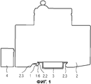
Фиг.1 показывает устройство для встраивания в ряд на одной U-образной шине.Figure 1 shows a device for mounting in a row on one U-shaped bus.
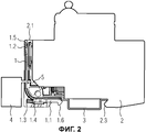
Фиг.2 показывает в виде частичного сечения устройство для встраивания в ряд из Фиг.1.Figure 2 shows in partial cross section a device for embedding in a row of Figure 1.
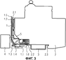
Фиг.3 показывает устройство для встраивания в ряд в виде частичного сечения в деблокированном состоянии.Figure 3 shows a device for embedding in a row in the form of a partial section in the unlocked state.
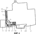
Фиг.4 показывает устройство для встраивания в ряд из Фиг.1 при демонтаже/монтаже.Figure 4 shows the device for embedding in a row from Figure 1 during dismantling / installation.
Фиг.5 показывает ползун для устройства для встраивания в ряд.Fig. 5 shows a slider for a row alignment device.
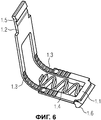
Фиг.6 показывает ползун для устройства встраивания в ряд с дополнительным пружинным элементом.6 shows a slider for a row alignment device with an additional spring element.
Фиг.1 показывает устройство 2 для встраивания в ряд на U-образной шине 3 в смонтированном состоянии. Защелкивающееся крепление устройства 2 для встраивания в ряд заблокировано, причем формованная часть 2.3 корпуса в комбинации с формованным элементом 1.6 ползуна 1 вместе с корпусом устройства 3 для встраивания в ряд охватывают U-образную шину 3 таким образом, что ведет к прочному удержанию устройства 2 для встраивания в ряд.Figure 1 shows a
Рядом с устройством 2 встраивания в ряд расположена сборная шина 4, которая вследствие близкого расположения поддерживает электрическое контактирование с клеммой 5 или другими клеммами.Next to the
Формованная часть 2.3 корпуса поддерживает движение деблокирования ползуна 1 вместе с формованной частью 1.6 корпуса. Далее, за счет выступа 2.2 корпуса достигается локальный зажим экстремума U-образной шины 3 в комбинации с формованным элементом 1.6 в блокированном состоянии. Это служит для дальнейшего прочного крепления устройства 2 для встраивания в ряд.The molded body part 2.3 supports the release movement of the
Фиг.4 показывает устройство 2 для встраивания в ряд из Фиг.1 в виде частичного сечения в заблокированном состоянии. При этом сеченая часть Фиг.2 ограничивается областью устройства 2 для встраивания в ряд, в котором расположена направляющая ползуна 1 и сам ползун 1.Figure 4 shows a
На исполнительном элементе 1.2 ползуна 1 предусмотрено место фиксации 1.5, которое в совокупности с контуром 2.1 корпуса обеспечивает стопорение ползуна 1 в деблокированной позиции. Таким образом, несмотря на выработку упругой силы вследствие изменения формы посредством направляющей ползуна 1 может достигаться закрепление, в результате чего может более просто производиться монтаж и демонтаж.On the actuating element 1.2 of the
Далее, выполнена клемма 5, с помощью которой встраиваемое в ряд устройство 2, которое выполнено, например, в качестве выключателя, может электрически соединяться со сборной шиной 4, причем электрическое соединение проходит насквозь по мере надобности через отверстие или несколько отверстий ползуна 1 в его области 1.3 соединения или в области, которая расположена вблизи области 1.3 соединения. Также представляется возможным преобразования необходимого для этого отверстия в качестве выемки внутри ползуна 1, которая не полностью охвачена ползуном 1.Next, terminal 5 is made, by means of which a row-mounted
Дополнительно вблизи деблокирующего элемента 1.1 может располагаться пружинный элемент 1.4, который по мере надобности может быть соединен с ползуном в качестве монолитного элемента. При этом пружинный элемент 1,4 служит для поддержания создания силы при деблокировании. Использование пружинного элемента 1.4 является опциональным и может приниматься во внимание в том случае, если вследствие проблем с пространством ползун 1 не может быть выполнен достаточно прочным для того, чтобы выработать соответствующую силу натяжения пружины, базирующуюся на своем эффекте запоминания формы.Additionally, a spring element 1.4 can be located near the release element 1.1, which, if necessary, can be connected to the slider as a monolithic element. In this case, the spring element 1.4 serves to maintain the creation of force during release. The use of the spring element 1.4 is optional and can be taken into account if, due to space problems, the
Фиг.3 показывает устройство 2 для встраивания в ряд из Фиг.1 в виде частичного сечения в деблокированном состоянии.Figure 3 shows the
Пользователь приводит в действие исполнительный элемент 1.2 и фиксирует позицию 1.5 с приданным ей контуром 2.1 корпуса. Устройство 2 для встраивания в ряд находится в деблокированном положении, причем часть U-образной шины 3, которая расположена на выступе 2.2 корпуса, свободно прилегает к корпусу устройства 2 для встраивания в ряд. Поддерживающий пружинный элемент 1.4 в этом состоянии нагружен сильнее, чем в положении блокировки.The user activates the actuator 1.2 and fixes the position 1.5 with the attached contour 2.1 of the housing. The device for
Предпочтительным образом ползун 1 содержит, по меньшей мере на образующий угол стороне ползуна 1, рифленую структуру, которая облегчает для ползуна 1 выработку оптимальной упругости также в изогнутом состоянии и уменьшает силы трения.Advantageously, the
Предпочтительным образом в данном случае не изображенное здесь отверстие ползуна 1 имеет для контактирования клеммы 5 со сборной шиной 4 форму, которая также поддерживает движение ползуна 1.Advantageously, in this case, the opening of the slider 1 (not shown) has a shape for contacting the terminal 5 with the
Фиг.4 показывает устройство 2 для встраивания в ряд из Фиг.1 при демонтаже или монтаже. Если устройство 2 для встраивания в ряд уже находится в разъединенном состоянии, как это показано на Фиг.3, то формованная часть 2.3 корпуса обводиться вокруг конца U-образной шины 3, причем в завершение устройство 2 встраивания в ряд может отводиться в сторону от сборной шины 3 (как правило, вперед). Это поддерживается частично имеющей форму стрелы формованной частью 1.6 блокировочного элемента 1.1.Figure 4 shows the
При монтаже или демонтаже место 1.5 фиксации остается подвешенным в соответствующем контуре 2.1 корпуса.When mounting or dismounting, the fixing location 1.5 remains suspended in the corresponding circuit 2.1 of the housing.
При монтаже выполняются те же этапы монтажа, как и при демонтаже, - конечно в противоположной последовательности. При этом ползун 1 находится в положении деблокирования, причем одновременно устройство 2 для встраивания в ряд или клемма 5 подключаются к контактам сборной шины 4. Альтернативно блокировочный элемент 1.1 перемещается посредством движения опрокидывания устройства 2 встраивания в ряд против направления блокировки, и вместе с ним перемещается весь ползун 1. В завершение выступ 2.2 корпуса вводится в прилегание с U-образной шиной 3, причем одновременно сформованная часть 2.3 занимает позицию позади U-образной шины 3. В завершение место 1.5 фиксации отцепляется из соответствующего контура 2.1 корпуса, в результате чего устройство для встраивания в ряд полностью укреплено.During installation, the same installation steps are performed as during dismantling, of course in the opposite sequence. In this case, the
Фиг.5 показывает толкатель 1 для устройства для встраивания в ряд с исполнительным элементом 1.2 и местом 1.5 фиксации, которое имеет форму крючка.5 shows a
Область 1.3 соединения разделена на два, имеющих форму полос, соединительных элемента, оба из которых соединяют по себе исполнительный элемент 1.2 с блокировочным элементом 1.1. Тем самым область 1.3 соединения образует в комбинации с исполнительным элементом 1.2 и блокировочным элементом 1.1 отверстие с большой поверхностью, которое оптимально пригодно для проведения проводников или электрических контактов. К тому же выполненное большим отверстие выгодно в отношении расхода материала, причем можно также уделить внимание жесткости ползуна 1, поскольку она определяет упругую силу сжатия пружины или силу возврата ползуна 1 в исходное положение.The connection region 1.3 is divided into two strip-shaped connecting elements, both of which connect the actuator 1.2 on their own with the blocking element 1.1. Thus, the connection region 1.3 forms, in combination with the actuating element 1.2 and the locking element 1.1, an opening with a large surface that is optimally suitable for conducting conductors or electrical contacts. In addition, a large hole made is advantageous in terms of material consumption, and one can also pay attention to the rigidity of the
Область 1.3 может выполняться гибкой. При этом отклонение силы не обязательно должно изменяться под прямым углом, а может принимать также и другие угловые положения. Кроме того, возможно наличие также большего количества отверстий или имеющих форму полосы формованных элементов соединительной области 1.3, в результате чего может, например, повышаться стабильность ползуна 1 или его возвращающая сила.Area 1.3 may be flexible. Moreover, the deviation of the force does not have to change at right angles, but can also take other angular positions. In addition, there may also be a larger number of holes or strip-shaped shaped elements of the connecting region 1.3, as a result of which, for example, the stability of the
Фиг.6 показывает ползун 1 для устройства встраивания в ряд с дополнительным пружинным элементом 1.4. Пружинный элемент 1.4 сформован в качестве монолитной детали на блокировочном элементе 1.1 и образует схожую с пружиной структуру. При этом пружинный элемент 1.4 может находиться в состоянии предварительного натяжения, так что обеспечивается надежное действие пружины для блокировки или фиксации устройства 2 для встраивания в ряд. Конечно, расположение пружинного элемента 1.4 означает дополнительные расходы и повышает стоимость изготовления ползуна.6 shows a
В качестве обобщения можно сказать, что изобретение касается защелкивающегося крепления для крепления корпуса, в частности устройства для встраивания в ряд, на шине с ползуном, причем ползун содержит исполнительный элемент, блокировочный элемент и соединительную область между обоими элементами. Предложенное изобретение позволяет указать защелкивающееся крепление, которое может удобным образом с возможностью отсоединения и благоприятно в стоимостном отношении изготовляться из расположенной в ряд структуры также при подключенных проводниках или сборных шинах. Для этого ползун изготовляется в качестве монолитного элемента и по меньшей мере его область соединения выполнена упругой и с возможностью возврата в исходное положение. Тем самым отпадает необходимость в использовании элементов, вырабатывающих дополнительную силу сжатия пружины, поскольку возвращающая сила сжатия пружины ползуна, которая постоянно отжимает его в позицию блокировки, генерируется исходя из запоминания формы ползуна.As a generalization, it can be said that the invention relates to a snap fastening for attaching a housing, in particular a device for mounting in a row, on a tire with a slider, the slider comprising an actuating element, a locking element and a connecting region between both elements. The proposed invention allows you to specify a snap fastener, which can be conveniently detachable and cost-efficiently made from a row-mounted structure also with connected conductors or busbars. For this, the slider is made as a monolithic element and at least its connection area is made elastic and can be returned to its original position. Thus, there is no need to use elements that generate additional spring compression force, since the returning spring compression force of the slider, which constantly presses it into the lock position, is generated based on the memory of the shape of the slider.
Claims (9)
Applications Claiming Priority (2)
| Application Number | Priority Date | Filing Date | Title |
|---|---|---|---|
| DE102007015470.6 | 2007-03-30 | ||
| DE102007015470A DE102007015470B4 (en) | 2007-03-30 | 2007-03-30 | Snap fastening for fastening a housing |
Publications (1)
| Publication Number | Publication Date |
|---|---|
| RU2415503C1 true RU2415503C1 (en) | 2011-03-27 |
Family
ID=39591694
Family Applications (1)
| Application Number | Title | Priority Date | Filing Date |
|---|---|---|---|
| RU2009140144/09A RU2415503C1 (en) | 2007-03-30 | 2008-03-14 | Clicking fixture to fix body |
Country Status (6)
| Country | Link |
|---|---|
| EP (1) | EP2132841B1 (en) |
| CN (1) | CN101647164B (en) |
| BR (1) | BRPI0809968B1 (en) |
| DE (1) | DE102007015470B4 (en) |
| RU (1) | RU2415503C1 (en) |
| WO (1) | WO2008119651A1 (en) |
Cited By (1)
| Publication number | Priority date | Publication date | Assignee | Title |
|---|---|---|---|---|
| RU2750857C2 (en) * | 2017-01-12 | 2021-07-05 | Ландис+Гир АГ | Casing unit and monitoring instrument comprising said unit |
Families Citing this family (8)
| Publication number | Priority date | Publication date | Assignee | Title |
|---|---|---|---|---|
| DE102010040322B4 (en) * | 2010-09-07 | 2016-10-13 | Siemens Aktiengesellschaft | Sliding device for fastening a housing and installation device with such a sliding device |
| DE102010061555B3 (en) | 2010-10-26 | 2012-04-26 | Stego-Holding Gmbh | fastening device |
| DE102011087209B4 (en) | 2011-11-28 | 2019-02-28 | Siemens Aktiengesellschaft | Electrical installation equipment |
| DE102012100974B4 (en) | 2012-02-07 | 2013-10-10 | Stego-Holding Gmbh | Fan and arrangement having such a fan |
| EP2626962A1 (en) | 2012-02-13 | 2013-08-14 | Siemens Aktiengesellschaft | Clamping assembly for fixing a housing to a rail |
| CN204046995U (en) * | 2014-09-09 | 2014-12-24 | 泰科电子(上海)有限公司 | Mounting brackets and control equipment |
| CN109982542A (en) * | 2019-05-07 | 2019-07-05 | 希望森兰科技股份有限公司 | Installation guide rail snap lock locking apparatus for electrical equipment |
| KR102316687B1 (en) * | 2019-12-30 | 2021-10-25 | 주식회사 오토닉스 | Device |
Citations (3)
| Publication number | Priority date | Publication date | Assignee | Title |
|---|---|---|---|---|
| DE19709811A1 (en) * | 1997-03-10 | 1998-09-17 | Siemens Ag | Releasable butt-mounted device e.g. line circuit-breaker |
| RU2001117499A (en) * | 1998-11-27 | 2003-06-10 | Легран | Auxiliary device for fastening the mechanism of equipment intended for fixing on the basis of the mounting box |
| DE10243383B3 (en) * | 2002-09-18 | 2004-02-05 | Siemens Ag | Electrical installation device carrier rail fixing uses spring-loaded slider with retention nose secured to housing of installation device |
Family Cites Families (8)
| Publication number | Priority date | Publication date | Assignee | Title |
|---|---|---|---|---|
| DE19504762C2 (en) * | 1995-02-04 | 2002-08-29 | Wago Verwaltungs Gmbh | Unlocking device for a snap fastening of an electr. or electronic component on a mounting rail |
| DE29710310U1 (en) | 1997-06-12 | 1997-09-18 | Siemens AG, 80333 München | Device that can be snapped onto mounting rails |
| DE29723752U1 (en) * | 1997-10-09 | 1999-04-01 | Phoenix Contact Gmbh & Co., 32825 Blomberg | Electronic device |
| FR2786619B1 (en) * | 1998-11-27 | 2003-07-25 | Legrand Sa | FIXING ACCESSORY FOR MECHANISM OF APPARATUS TO SUBJECT TO THE BASE OF A CHUTE |
| DE10047676C1 (en) * | 2000-09-25 | 2002-04-25 | Phoenix Contact Gmbh & Co | Housing for an electronic device |
| FR2834826B1 (en) * | 2002-01-14 | 2004-10-08 | Schneider Electric Ind Sa | DEVICE FOR REMOVABLE FIXING OF AN ELECTRICAL APPARATUS ON A MOUNTING RAIL AND ELECTRICAL APPARATUS EQUIPPED WITH SUCH A DEVICE |
| DE50309839D1 (en) * | 2003-03-19 | 2008-06-26 | Siemens Ag | Snap-on device to a mounting rail |
| FR2879833B1 (en) * | 2004-12-16 | 2008-06-13 | Schneider Electric Ind Sas | DEVICE FOR LOCKING AN ELECTRICAL APPARATUS ON A SUPPORT RAIL |
-
2007
- 2007-03-30 DE DE102007015470A patent/DE102007015470B4/en not_active Expired - Fee Related
-
2008
- 2008-03-14 EP EP08717856.2A patent/EP2132841B1/en active Active
- 2008-03-14 BR BRPI0809968-5A patent/BRPI0809968B1/en active IP Right Grant
- 2008-03-14 WO PCT/EP2008/053115 patent/WO2008119651A1/en not_active Ceased
- 2008-03-14 CN CN200880010253XA patent/CN101647164B/en active Active
- 2008-03-14 RU RU2009140144/09A patent/RU2415503C1/en not_active IP Right Cessation
Patent Citations (3)
| Publication number | Priority date | Publication date | Assignee | Title |
|---|---|---|---|---|
| DE19709811A1 (en) * | 1997-03-10 | 1998-09-17 | Siemens Ag | Releasable butt-mounted device e.g. line circuit-breaker |
| RU2001117499A (en) * | 1998-11-27 | 2003-06-10 | Легран | Auxiliary device for fastening the mechanism of equipment intended for fixing on the basis of the mounting box |
| DE10243383B3 (en) * | 2002-09-18 | 2004-02-05 | Siemens Ag | Electrical installation device carrier rail fixing uses spring-loaded slider with retention nose secured to housing of installation device |
Cited By (2)
| Publication number | Priority date | Publication date | Assignee | Title |
|---|---|---|---|---|
| RU2750857C2 (en) * | 2017-01-12 | 2021-07-05 | Ландис+Гир АГ | Casing unit and monitoring instrument comprising said unit |
| US11199427B2 (en) | 2017-01-12 | 2021-12-14 | Landis+Gyr Ag | Enclosure assembly and metering apparatus comprising same |
Also Published As
| Publication number | Publication date |
|---|---|
| WO2008119651A1 (en) | 2008-10-09 |
| BRPI0809968A2 (en) | 2014-10-07 |
| BRPI0809968B1 (en) | 2019-07-16 |
| EP2132841A1 (en) | 2009-12-16 |
| DE102007015470A1 (en) | 2008-10-02 |
| CN101647164A (en) | 2010-02-10 |
| DE102007015470B4 (en) | 2010-06-24 |
| CN101647164B (en) | 2012-05-30 |
| EP2132841B1 (en) | 2014-10-29 |
Similar Documents
| Publication | Publication Date | Title |
|---|---|---|
| RU2415503C1 (en) | Clicking fixture to fix body | |
| US9577365B1 (en) | Holding frame for holding plug connector modules | |
| CN101925281B (en) | Integrated DIN rail attachment feature for superior attachment | |
| CN110537299B (en) | Retaining frame for heavy-duty plug connectors | |
| US5907476A (en) | Self-locking rail securement device | |
| US6431909B1 (en) | DIN rail attachment method and apparatus | |
| US9124081B2 (en) | Power distribution box having interlocking support modules | |
| US5572776A (en) | Fastener employing a Bi-stable mechanism | |
| US8727288B2 (en) | Snap-in bracket for attaching cabling to a support | |
| US20160211612A1 (en) | Electrical connection terminal | |
| WO2009046993A1 (en) | Vibration-damping contact element | |
| US7348511B2 (en) | Button device for computer bezel | |
| JP2013503440A (en) | Connector system | |
| US6903275B1 (en) | Mounting device for a wire harness shield | |
| JP7329569B2 (en) | Retaining mechanism for attaching a technical equipment unit to a mounting rail and technical equipment unit having such a retaining mechanism | |
| US20050250353A1 (en) | Electrical connector | |
| US20030014850A1 (en) | Retaining clip for panel mounted input/output connector | |
| CN109755798A (en) | Modular retaining frame for plug connectors | |
| KR950010192A (en) | Electrical connector | |
| CN102640371B (en) | For hook and the locking mechanism of standard bus-bar | |
| CN102438416A (en) | Slider for securing the housing | |
| CN102073342A (en) | Computer case locking device | |
| US20030048623A1 (en) | Capture device for boards having variable thickness | |
| US11450490B2 (en) | Mechanical interlock assemblies for panelboards and related systems and methods | |
| US20200256364A1 (en) | Latch connection means for connecting two components |
Legal Events
| Date | Code | Title | Description |
|---|---|---|---|
| MM4A | The patent is invalid due to non-payment of fees |
Effective date: 20120315 |