RU2415302C1 - Deep-well pumping unit for tubingless operation of wells - Google Patents
Deep-well pumping unit for tubingless operation of wells Download PDFInfo
- Publication number
- RU2415302C1 RU2415302C1 RU2010104686/06A RU2010104686A RU2415302C1 RU 2415302 C1 RU2415302 C1 RU 2415302C1 RU 2010104686/06 A RU2010104686/06 A RU 2010104686/06A RU 2010104686 A RU2010104686 A RU 2010104686A RU 2415302 C1 RU2415302 C1 RU 2415302C1
- Authority
- RU
- Russia
- Prior art keywords
- cylinder
- cable
- pump
- plunger
- hollow
- Prior art date
Links
Images
Abstract
Description
Изобретение относится к технике для добычи нефти, в частности штанговыми насосами, и может быть использовано при эксплуатации добывающих скважин, в том числе для подъема из них высоковязкой продукции.The invention relates to techniques for oil production, in particular sucker rod pumps, and can be used in the operation of production wells, including for lifting high-viscosity products from them.
Известно устройство для беструбной эксплуатации глубинных поршневых насосов (см. а.с. SU 494535, F04B 47/00, 1976), содержащее глубинный поршневой насос, пакер, в центральном канале которого размещен приемный фильтр с перфорированной цилиндрической поверхностью, снабженной уплотнениями.A device is known for tubeless operation of deep piston pumps (see AS SU 494535, F04B 47/00, 1976), comprising a deep piston pump, a packer, in the central channel of which there is a receiving filter with a perforated cylindrical surface provided with seals.
Недостатками известного устройства для беструбной эксплуатации глубинных поршневых насосов являются поочередный спуск (подъем) в скважину пакера и глубинного насоса, циклическая нагрузка на пакер при работе глубинного насоса, отсутствие канала связи устья с подпакерной зоной.The disadvantages of the known device for tubeless operation of deep piston pumps are the sequential descent (rise) into the well of the packer and the deep pump, the cyclic load on the packer during the operation of the deep pump, the absence of a channel between the mouth and the sub-packer zone.
Известна глубинно-насосная установка для эксплуатации добывающих скважин (см. патент RU 33180, F04B 47/02, 2003), включающая штанговый насос, содержащий цилиндр, приемный клапан, плунжер с управляемым нагнетательным клапаном, присоединенный к колонне насосных штанг с центраторами, узел крепления, якорный пакер и перепускное устройство, размещенное между приемным клапаном и узлом крепления.A well-known submersible installation for the operation of production wells (see patent RU 33180, F04B 47/02, 2003), including a sucker rod pump comprising a cylinder, a suction valve, a plunger with a controlled discharge valve, connected to a string of pump rods with centralizers, an attachment unit , an anchor packer and a bypass device located between the inlet valve and the mount.
Недостатками известной глубинно-насосной установки для эксплуатации добывающих скважин являются поочередный спуск (подъем) в скважину якорного пакера и штангового насоса, циклическая нагрузка на якорный пакер при работе штангового насоса, отсутствие канала связи устья с подпакерной зоной.The disadvantages of the well-known deep-well installation for operating production wells are the alternate descent (ascent) of the anchor packer and the sucker rod pump into the well, the cyclic load on the anchor packer during the operation of the sucker rod pump, and the absence of a communication channel between the mouth and the sub-packer zone.
Наиболее близкой к предлагаемой установке по технической сущности и достигаемому результату является глубинно-насосная установка для подъема продукции по эксплуатационной колонне скважины (см. патент RU 2361115, F04B 47/02, 2009), включающая штанговый насос, содержащий цилиндр, приемный клапан, плунжер с управляемым нагнетательным клапаном, присоединенный к колонне насосных штанг с центраторами, пакер, выполненный в виде самоуплотняющихся манжет, полый хвостовик с упором, снабженный ниже пакера и выше упора боковыми отверстиями, перепускные устройства.Closest to the proposed installation in technical essence and the achieved result is a deep pump installation for lifting products along the production casing of a well (see patent RU 2361115, F04B 47/02, 2009), including a sucker rod pump containing a cylinder, a receiving valve, a plunger with controlled by a pressure valve attached to the string of pump rods with centralizers, a packer made in the form of self-sealing cuffs, a hollow shank with an emphasis, provided with side openings below the packer and above the stop, bypass devices ystva.
Хотя в известной глубинно-насосной установке для подъема продукции по эксплуатационной колонне скважины совмещен спуск (подъем) пакера и штангового насоса, снята часть циклической нагрузки с пакера при работе штангового насоса, однако отсутствует канал связи устья с подпакерной зоной, что не позволяет размещать глубинные датчики и контролировать параметры в подпакерной зоне в режиме реального времени.Although the well-known deep-pump installation for lifting products along the production casing of the well combines the descent (rise) of the packer and the sucker rod pump, a part of the cyclic load from the packer during the operation of the sucker pump is removed, however, there is no communication channel between the wellhead and the sub-packer zone, which does not allow placing depth sensors and control the parameters in the subpacker zone in real time.
Технической задачей предлагаемого изобретения является повышение эффективности беструбной эксплуатации скважины и работы глубинно-насосной установки за счет оптимизации режима работы на основании данных, полученных в режиме реального времени на приеме штангового насоса под пакером, а также данных о параметрах пласта.The technical task of the invention is to increase the efficiency of pipeless operation of the well and the operation of the downhole pump unit by optimizing the operating mode based on real-time data received at the sucker rod pump reception under the packer, as well as data on the formation parameters.
Поставленная техническая задача решается глубинно-насосной установкой для беструбной эксплуатации скважин, включающей штанговый насос, содержащий цилиндр, приемный клапан, плунжер с управляемым нагнетательным клапаном, присоединенный к колонне насосных штанг с центраторами, пакер, выполненный в виде самоуплотняющихся манжет, полый хвостовик с упором, снабженный ниже пакера и выше упора боковыми отверстиями.The stated technical problem is solved by a deep-well pump installation for tubeless operation of wells, including a sucker rod pump containing a cylinder, a suction valve, a plunger with a controlled discharge valve connected to a string of pump rods with centralizers, a packer made in the form of self-sealing cuffs, a hollow shank with an emphasis, equipped with side openings below the packer and above the stop.
Новым является то, что в глубинно-насосной установке для беструбной эксплуатации скважин верх цилиндра соединен с патрубком, снабженным боковыми отверстиями и центратором, а в верхнем конце сужением и выполненным с внутренним диаметром большим, чем внутренний диаметр цилиндра и с длиной большей, чем длина плунжера, плунжер с управляемым нагнетательным клапаном присоединен к колонне насосных штанг с центраторами через нижний полый шток, нижняя, до нагнетательного клапана, часть которого выполнена длиной, равной длине цилиндра и герметично пропущена через приемный клапан с возможностью взаимного осевого перемещения при ограниченном осевом перемещении приемного клапана относительно цилиндра, а верхний конец нижнего полого штока, снабженный кабельным вводом, соединен с колонной насосных штанг, верхний конец которой соединен с нижним концом, снабженным кабельным вводом, верхнего полого штока, пропущенного через устьевой сальник, к колонне насосных штанг прикреплен кабель, нижний и верхний концы которого герметично пропущены через кабельные вводы и полости соответствующих полых штоков, нижний конец кабеля соединен с глубинным датчиком, а верхний - со вторичным прибором на устье, боковые отверстия полого хвостовика выполнены в виде приемных фильтров.What is new is that in a deep-well pumping installation for tubeless operation of wells, the top of the cylinder is connected to a nozzle equipped with side holes and a centralizer, and at the upper end it is constricted and made with an inner diameter larger than the inner diameter of the cylinder and with a length greater than the length of the plunger , a plunger with a controlled discharge valve is connected to the string of pump rods with centralizers through the lower hollow rod, the lower one, to the discharge valve, part of which is made equal to the length of the cylinder and is tight but it is passed through a receiving valve with the possibility of mutual axial movement with limited axial movement of the receiving valve relative to the cylinder, and the upper end of the lower hollow rod equipped with a cable entry is connected to the column of pump rods, the upper end of which is connected to the lower end equipped with a cable entry of the upper hollow a rod passed through a wellhead seal, a cable is attached to the string of pump rods, the lower and upper ends of which are hermetically passed through cable entries and cavities correspondingly hollow rods, the lower end of the cable is connected to the depth sensor, and the upper end to the secondary device at the mouth, the side openings of the hollow shank are made in the form of receiving filters.
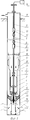
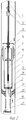
На фиг.1 схематично показан общий вид глубинно-насосной установки для беструбной эксплуатации скважин; на фиг.2 - то же, при ее спуске-подъеме в скважине.Figure 1 schematically shows a General view of a deep-well pumping unit for pipeless operation of wells; figure 2 is the same when it is the descent, ascent in the well.
Глубинно-насосная установка для беструбной эксплуатации скважин (см. фиг.1) включает штанговый насос, состоящий из цилиндра 1. приемного клапана 2, плунжера 3 с управляемым нагнетательным клапаном 4, присоединенного к колонне насосных штанг 5 с центраторами 6 через нижний полый шток 7, верхний конец которого оснащен кабельным вводом 8. Верхний конец колонны насосных штанг 5 соединен с верхним полым штоком 9, оснащенным в нижнем конце кабельным вводом 10 и пропущенным через устьевой сальник 11. К колонне насосных штанг 5 прикреплен кабель 12, нижний и верхний концы которого герметично пропущены через кабельные вводы 8 и 10 и полости соответствующих полых штоков 7 и 9. Нижний конец кабеля 12 соединен с глубинным датчиком 13, а верхний - со вторичным прибором 14 на устье. К верхнему концу цилиндра 1 присоединен патрубок 15 с боковыми отверстиями 16, центратором 17 и с сужением 18 в верхнем конце, а к нижнему концу цилиндра 1 присоединен хвостовик 19 с приемными фильтрами 20, 21, упором 22 и пакером 23, выполненным в виде самоуплотняющихся манжет.The downhole pump installation for tubeless operation of wells (see Fig. 1) includes a sucker rod pump consisting of a
Глубинно-насосная установка для беструбной эсплуатации скважин работает следующим образом. Глубинно-насосную установку собирают на месте эксплуатации и на колонне насосных штанг 5 (см. фиг.2) совместно с кабелем 12 спускают в скважину 24, прикрепляя его к колонне насосных штанг 5. При спуске оборудования хвостовик 19 и цилиндр 1 с патрубком 15 под действием силы тяжести висят на плунжере 3, который взаимодействует с сужением 18 патрубка 15, а нижний полый шток 7 выходит из отверстия 25 приемного клапана 2. В таком положении плунжера 3 относительно патрубка 15 и нижнего конца нижнего полого штока 7 относительно приемного клапана 2 открывается проходной канал между нижним концом плунжера 3 и верхом цилиндра 1, а также между нижним концом нижнего полого штока 7 и приемным клапаном 2, при этом полость хвостовика 19 сообщается с полостью скважины 24, расположенной под пакером 23. Жидкость, находящаяся в скважине 24 под пакером 23, перетекает через приемные фильтры 20, 21, по полости хвостовика 19, через отверстие 25 в приемном клапане 2, по полости цилиндра 1, через проходной канал между нижним концом плунжера 3 и верхом цилиндра 1, кольцевой канал между плунжером 3 и патрубком 15, через отверстие 16 в патрубке 15 в полость скважины 24 над пакером 23.The deep-pump installation for pipeless operation of wells works as follows. The downhole pump installation is assembled at the operating site and on the pump rod string 5 (see FIG. 2) together with the
В конце спуска оборудования хвостовик 19 (см. фиг.1) через упор 22 устанавливается на забое скважины 24. Плунжер 3, соединенный с колонной насосных штанг 5 через нижний полый шток 7, продолжает перемещение относительно патрубка 15, а нижний полый шток 7 - относительно приемного клапана 2, далее плунжер 3 входит в полость цилиндра 1, а нижний полый шток 7 - в отверстие 25 приемного клапана 2.At the end of the descent of the equipment, the liner 19 (see Fig. 1) is installed through the
После подгонки длины колонны насосных штанг 5 и пропуска кабеля 12 через кабельный ввод 10, полость верхнего полого штока 9 и соединения конца кабеля 12 со вторичным прибором 14 на устье глубинно-насосная установка запускается в работу. Привод (не показан) через колонну насосных штанг 5 с центраторами 6 передает плунжеру 3 возвратно-поступательное движение. Продукция скважины поступает в штанговый насос из подпакерной полости скважины 24 через приемный фильтр 20, по полости хвостовика 19 и нагнетается через отверстия 16 в патрубке 15 в надпакерную полость скважины 24, по которой осуществляется подъем продукции к устью.After adjusting the length of the string of
Далее циклы работы повторяются.Further work cycles are repeated.
Центраторы 6 предотвращают взаимное соприкосновение и износ колонны насосных штанг 5, кабеля 12 и внутренней поверхности стенок скважины 24.
В плунжере 3 применен управляемый нагнетательный клапан 4, открывающийся в начале движения хода колонны штанг 5 вниз независимо от перепада давления над и под управляемым нагнетательным клапаном 4, что достигается жесткой связью запирающего элемента управляемого нагнетательного клапана 4 с нижним полым штоком 7, соединенным с колонной насосных штанг 5. При этом попавший в штанговый насос вместе с продукцией газ через открытый управляемый нагнетательный клапан 4 поступает в надпакерную полость скважины 24. Применение плунжера 3 с управляемым нагнетательным клапаном 4 позволяет уменьшить вредное влияние газа на работоспособность и производительность штангового насоса. С началом хода колонны насосных штанг 5 и нижнего полого штока 7 вверх нагнетательный клапан 4 закрывается, давление под плунжером 3 снижается, открывается приемный клапан 2 и продукция скважины 24 поступает в штанговый насос. Герметичный пропуск нижнего полого штока 7 через приемный клапан 2 с возможностью взаимного осевого перемещения при ограниченном осевом перемещении приемного клапана относительно цилиндра вызывает принудительное открытие и закрытие приемного клапана 2 от нижнего полого штока 7 за счет трения в узле герметичного пропуска, что обеспечивает более четкое срабатывание приемного клапана 2, особенно при подъеме высоковязкой продукции, предотвращает его «залипание» и срыв подачи штангового насоса, повышает таким образом его работоспособность и производительность. Кроме того, при ходе колонны насосных штанг 5 вниз создается дополнительная гидравлическая нагрузка на колонну насосных штанг 5 вниз за счет разности давления на верхний и нижний концы нижнего полого штока 7, что обеспечивает гарантированное без зависания движение колонны насосных штанг 5 вниз, особенно в высоковязкой жидкости, тем самым повышается надежность работы штангового насоса.In the
Соединение верха цилиндра 1 с патрубком 15, снабженным боковыми отверстиями 16 и сужением 18 в верхнем конце патрубка 15, выполненного с внутренним диаметром большим, чем внутренний диаметр цилиндра 1, и длиной большей, чем длина плунжера 3 совместно с герметичным пропуском нижней части нижнего полого штока 7, длиной до нагнетательного клапана 4, равной длине цилиндра 1, через приемный клапан 2 с возможностью взаимного осевого перемещения при ограниченном осевом перемещении приемного клапана 2 относительно цилиндра 1 и с соединением верхнего конца нижнего полого штока 7 с колонной насосных штанг 5 позволяет при спуске-подъеме оборудования сообщать надпакерную и подпакерную полости скважины 24, что исключает поршневание жидкости пакером 23 при перемещениях оборудования по стволу скважины 24 (см. фиг.2). Это значительно сокращает время спуска оборудования в скважину 24 при монтаже, а при демонтаже позволяет извлечь все оборудование из скважины 24 обычной колонной насосных штанг 5 за счет исключения нагрузки на нее от веса столба жидкости в скважине 24. По этой же причине не происходит загрязнения приустьевой площадки скважинной жидкостью, которая из надпакерной полости скважины 24 через отверстия 16 в патрубке 15, кольцевой канал между плунжером 3 и патрубком 15, а также между нижним концом плунжера 3 и верхом цилиндра 1, полость цилиндра 1, отверстие 25 в приемном клапане 2 и нижний фильтр 21 вся сливается в скважину 24 при извлечении оборудования из нее.The connection of the top of the
Снабжение патрубка 15 центратором 17 исключает возможность раскачивания цилиндра 1 при работе штангового насоса под действием усилий при движении колонны насосных штанг 5 в скважине 24, что предотвращает возникновение дополнительных напряжений в пакере 23, снижающих его работоспособность.The supply of the
Выполнение боковых отверстий полого хвостовика 19 в виде приемных фильтров 20, 21 предотвращает попадание на прием штангового насоса крупных механических примесей, снижающих надежность его работы.The implementation of the side holes of the
К колонне насосных штанг 5 прикреплен кабель 12 (см. фиг.1), нижний конец которого пропущен герметично через кабельный ввод 8 и полость нижнего полого штока 7 и соединен с глубинным датчиком 13, а верхний конец кабеля 12 пропущен герметично через кабельный ввод 10 и полость верхнего полого штока 9, пропущенного через устьевой сальник 11, и соединен со вторичным прибором 14, расположенным на устье скважины 24, что позволяет в режиме реального времени получать на устье скважины 24 данные о параметрах под пакером 23 на приеме штангового насоса при его работе и о параметрах пласта после остановки штангового насоса, на основании которых можно согласовывать работу штангового насоса и пласта и оптимизировать режим работы штангового насоса.A
Использование предлагаемой глубинно-насосной установки для беструбной эксплуатации скважин позволяет значительно повысить эффективность беструбной эксплуатации скважины глубинно-насосной установкой за счет оптимизации режима работы на основании данных, полученных в режиме реального времени на прием штангового насоса под пакером, а также данных о параметрах пласта.The use of the proposed deep-well pump installation for pipeless well operation can significantly increase the efficiency of pipeless well operation with a deep-well pumping unit by optimizing the operating mode based on real-time data received at the sucker rod pump under the packer, as well as data on formation parameters.
Claims (1)
Priority Applications (1)
| Application Number | Priority Date | Filing Date | Title |
|---|---|---|---|
| RU2010104686/06A RU2415302C1 (en) | 2010-02-10 | 2010-02-10 | Deep-well pumping unit for tubingless operation of wells |
Applications Claiming Priority (1)
| Application Number | Priority Date | Filing Date | Title |
|---|---|---|---|
| RU2010104686/06A RU2415302C1 (en) | 2010-02-10 | 2010-02-10 | Deep-well pumping unit for tubingless operation of wells |
Publications (1)
| Publication Number | Publication Date |
|---|---|
| RU2415302C1 true RU2415302C1 (en) | 2011-03-27 |
Family
ID=44052903
Family Applications (1)
| Application Number | Title | Priority Date | Filing Date |
|---|---|---|---|
| RU2010104686/06A RU2415302C1 (en) | 2010-02-10 | 2010-02-10 | Deep-well pumping unit for tubingless operation of wells |
Country Status (1)
| Country | Link |
|---|---|
| RU (1) | RU2415302C1 (en) |
Cited By (1)
| Publication number | Priority date | Publication date | Assignee | Title |
|---|---|---|---|---|
| RU2740375C1 (en) * | 2020-08-10 | 2021-01-13 | Общество с ограниченной ответственностью "ЛУКОЙЛ-ПЕРМЬ" | Well pumping unit with anchor unit for pipeless operation of small-diameter wells |
-
2010
- 2010-02-10 RU RU2010104686/06A patent/RU2415302C1/en not_active IP Right Cessation
Cited By (1)
| Publication number | Priority date | Publication date | Assignee | Title |
|---|---|---|---|---|
| RU2740375C1 (en) * | 2020-08-10 | 2021-01-13 | Общество с ограниченной ответственностью "ЛУКОЙЛ-ПЕРМЬ" | Well pumping unit with anchor unit for pipeless operation of small-diameter wells |
Similar Documents
| Publication | Publication Date | Title |
|---|---|---|
| US20090145595A1 (en) | Gas assisted downhole pump | |
| RU2474727C1 (en) | Borehole pump unit | |
| WO2006083497A2 (en) | Pumping system and method for recovering fluid from a well | |
| US20150017036A1 (en) | Reciprocating subsurface pump | |
| RU2361115C1 (en) | Bottomhole pump set for product lifting along well flow string | |
| RU2498058C1 (en) | Oil-well sucker-rod pumping unit for water pumping to stratum | |
| RU2364708C1 (en) | Unit borehole rod pumping with double-acting pump | |
| RU2415302C1 (en) | Deep-well pumping unit for tubingless operation of wells | |
| RU85547U1 (en) | INSTALLATION FOR SIMULTANEOUS-SEPARATE OPERATION OF TWO LAYERS | |
| RU166549U1 (en) | PUMP INSTALLATION FOR OPERATION OF TILT-DIRECTED WELLS WITH A LARGE VERTICAL DISTANCE | |
| RU2738615C1 (en) | Method for simultaneous separate production of oil from two formations of one well by production string | |
| RU63864U1 (en) | INSTALLING A Borehole PUMPBAR PUMP WITH A DOUBLE ACTION PUMP | |
| RU2321772C1 (en) | Oil-well sucker-rod pump | |
| NO20180149A1 (en) | Apparatus for transferring a reciprocating movement from a machinery arranged at a surface to a device located downhole in a subterranean well, and method of producing well fluids | |
| RU2539459C1 (en) | Oil-well sucker-rod pumping unit | |
| RU53737U1 (en) | DEPTH BAR PIPE PUMP WITH REMOVABLE SUCTION VALVE | |
| RU2578093C1 (en) | Plant for simultaneous separate operation of two formations | |
| RU2318992C1 (en) | Oil well pumping unit for dual reservoir pumping | |
| RU99832U1 (en) | DEPTH PUMPING UNIT FOR CIRCUITless OPERATION OF WELLS | |
| RU2528469C1 (en) | Pump unit for separate operation of two beds | |
| RU33180U1 (en) | Submersible pumping unit for operation of producing wells | |
| RU2720845C1 (en) | Downhole pump filter | |
| RU165961U1 (en) | INSTALLATION FOR SEPARATE OIL AND WATER PRODUCTION FROM A HIGHLY WATERED OIL WELL | |
| RU2798647C1 (en) | Downhole pumping unit for pipeless well operation | |
| RU2165010C1 (en) | Well sucker-rod pump |
Legal Events
| Date | Code | Title | Description |
|---|---|---|---|
| MM4A | The patent is invalid due to non-payment of fees |
Effective date: 20120211 |