RU2410306C2 - Liner for containers designed for multiple components - Google Patents
Liner for containers designed for multiple components Download PDFInfo
- Publication number
- RU2410306C2 RU2410306C2 RU2008131903A RU2008131903A RU2410306C2 RU 2410306 C2 RU2410306 C2 RU 2410306C2 RU 2008131903 A RU2008131903 A RU 2008131903A RU 2008131903 A RU2008131903 A RU 2008131903A RU 2410306 C2 RU2410306 C2 RU 2410306C2
- Authority
- RU
- Russia
- Prior art keywords
- container
- liner
- outlet
- attached
- sealing
- Prior art date
Links
Images

Classifications
-
- B—PERFORMING OPERATIONS; TRANSPORTING
- B65—CONVEYING; PACKING; STORING; HANDLING THIN OR FILAMENTARY MATERIAL
- B65D—CONTAINERS FOR STORAGE OR TRANSPORT OF ARTICLES OR MATERIALS, e.g. BAGS, BARRELS, BOTTLES, BOXES, CANS, CARTONS, CRATES, DRUMS, JARS, TANKS, HOPPERS, FORWARDING CONTAINERS; ACCESSORIES, CLOSURES, OR FITTINGS THEREFOR; PACKAGING ELEMENTS; PACKAGES
- B65D51/00—Closures not otherwise provided for
- B65D51/24—Closures not otherwise provided for combined or co-operating with auxiliary devices for non-closing purposes
- B65D51/28—Closures not otherwise provided for combined or co-operating with auxiliary devices for non-closing purposes with auxiliary containers for additional articles or materials
-
- B—PERFORMING OPERATIONS; TRANSPORTING
- B65—CONVEYING; PACKING; STORING; HANDLING THIN OR FILAMENTARY MATERIAL
- B65D—CONTAINERS FOR STORAGE OR TRANSPORT OF ARTICLES OR MATERIALS, e.g. BAGS, BARRELS, BOTTLES, BOXES, CANS, CARTONS, CRATES, DRUMS, JARS, TANKS, HOPPERS, FORWARDING CONTAINERS; ACCESSORIES, CLOSURES, OR FITTINGS THEREFOR; PACKAGING ELEMENTS; PACKAGES
- B65D85/00—Containers, packaging elements or packages, specially adapted for particular articles or materials
- B65D85/70—Containers, packaging elements or packages, specially adapted for particular articles or materials for materials not otherwise provided for
- B65D85/72—Containers, packaging elements or packages, specially adapted for particular articles or materials for materials not otherwise provided for for edible or potable liquids, semiliquids, or plastic or pasty materials
- B65D85/73—Containers, packaging elements or packages, specially adapted for particular articles or materials for materials not otherwise provided for for edible or potable liquids, semiliquids, or plastic or pasty materials with means specially adapted for effervescing the liquids, e.g. for forming bubbles or beer head
-
- B—PERFORMING OPERATIONS; TRANSPORTING
- B65—CONVEYING; PACKING; STORING; HANDLING THIN OR FILAMENTARY MATERIAL
- B65D—CONTAINERS FOR STORAGE OR TRANSPORT OF ARTICLES OR MATERIALS, e.g. BAGS, BARRELS, BOTTLES, BOXES, CANS, CARTONS, CRATES, DRUMS, JARS, TANKS, HOPPERS, FORWARDING CONTAINERS; ACCESSORIES, CLOSURES, OR FITTINGS THEREFOR; PACKAGING ELEMENTS; PACKAGES
- B65D51/00—Closures not otherwise provided for
- B65D51/24—Closures not otherwise provided for combined or co-operating with auxiliary devices for non-closing purposes
- B65D51/28—Closures not otherwise provided for combined or co-operating with auxiliary devices for non-closing purposes with auxiliary containers for additional articles or materials
- B65D51/2807—Closures not otherwise provided for combined or co-operating with auxiliary devices for non-closing purposes with auxiliary containers for additional articles or materials the closure presenting means for placing the additional articles or materials in contact with the main contents by acting on a part of the closure without removing the closure, e.g. by pushing down, pulling up, rotating or turning a part of the closure, or upon initial opening of the container
- B65D51/2857—Closures not otherwise provided for combined or co-operating with auxiliary devices for non-closing purposes with auxiliary containers for additional articles or materials the closure presenting means for placing the additional articles or materials in contact with the main contents by acting on a part of the closure without removing the closure, e.g. by pushing down, pulling up, rotating or turning a part of the closure, or upon initial opening of the container the additional article or materials being released by displacing or removing an element enclosing it
- B65D51/2864—Closures not otherwise provided for combined or co-operating with auxiliary devices for non-closing purposes with auxiliary containers for additional articles or materials the closure presenting means for placing the additional articles or materials in contact with the main contents by acting on a part of the closure without removing the closure, e.g. by pushing down, pulling up, rotating or turning a part of the closure, or upon initial opening of the container the additional article or materials being released by displacing or removing an element enclosing it the element being a plug or like element closing a passage between the auxiliary container and the main container
-
- B—PERFORMING OPERATIONS; TRANSPORTING
- B65—CONVEYING; PACKING; STORING; HANDLING THIN OR FILAMENTARY MATERIAL
- B65D—CONTAINERS FOR STORAGE OR TRANSPORT OF ARTICLES OR MATERIALS, e.g. BAGS, BARRELS, BOTTLES, BOXES, CANS, CARTONS, CRATES, DRUMS, JARS, TANKS, HOPPERS, FORWARDING CONTAINERS; ACCESSORIES, CLOSURES, OR FITTINGS THEREFOR; PACKAGING ELEMENTS; PACKAGES
- B65D81/00—Containers, packaging elements, or packages, for contents presenting particular transport or storage problems, or adapted to be used for non-packaging purposes after removal of contents
- B65D81/32—Containers, packaging elements, or packages, for contents presenting particular transport or storage problems, or adapted to be used for non-packaging purposes after removal of contents for packaging two or more different materials which must be maintained separate prior to use in admixture
- B65D81/3216—Rigid containers disposed one within the other
- B65D81/3222—Rigid containers disposed one within the other with additional means facilitating admixture
-
- A—HUMAN NECESSITIES
- A61—MEDICAL OR VETERINARY SCIENCE; HYGIENE
- A61J—CONTAINERS SPECIALLY ADAPTED FOR MEDICAL OR PHARMACEUTICAL PURPOSES; DEVICES OR METHODS SPECIALLY ADAPTED FOR BRINGING PHARMACEUTICAL PRODUCTS INTO PARTICULAR PHYSICAL OR ADMINISTERING FORMS; DEVICES FOR ADMINISTERING FOOD OR MEDICINES ORALLY; BABY COMFORTERS; DEVICES FOR RECEIVING SPITTLE
- A61J1/00—Containers specially adapted for medical or pharmaceutical purposes
- A61J1/14—Details; Accessories therefor
- A61J1/20—Arrangements for transferring or mixing fluids, e.g. from vial to syringe
- A61J1/2003—Accessories used in combination with means for transfer or mixing of fluids, e.g. for activating fluid flow, separating fluids, filtering fluid or venting
- A61J1/202—Separating means
- A61J1/2037—Separating means having valve means
-
- A—HUMAN NECESSITIES
- A61—MEDICAL OR VETERINARY SCIENCE; HYGIENE
- A61J—CONTAINERS SPECIALLY ADAPTED FOR MEDICAL OR PHARMACEUTICAL PURPOSES; DEVICES OR METHODS SPECIALLY ADAPTED FOR BRINGING PHARMACEUTICAL PRODUCTS INTO PARTICULAR PHYSICAL OR ADMINISTERING FORMS; DEVICES FOR ADMINISTERING FOOD OR MEDICINES ORALLY; BABY COMFORTERS; DEVICES FOR RECEIVING SPITTLE
- A61J1/00—Containers specially adapted for medical or pharmaceutical purposes
- A61J1/14—Details; Accessories therefor
- A61J1/20—Arrangements for transferring or mixing fluids, e.g. from vial to syringe
- A61J1/2093—Containers having several compartments for products to be mixed
Abstract
Description
Данное изобретение относится к вкладышам для контейнеров, которые содержат два или более различных веществ или компонентов, хранящихся раздельно и смешиваемых между собой во время открытия контейнера.This invention relates to container liners that contain two or more different substances or components stored separately and mixed together during opening of the container.
Имеется множество сфер деятельности, в которых применяются или необходимы контейнеры, предназначенные для нескольких компонентов, в частности контейнеры с двумя компонентами. Так, существуют определенные фармацевтические композиции, которые вводятся в виде смеси, но которые являются неустойчивыми, если они находятся в виде смеси в течение длительного периода. Соответственно, компоненты подобной композиции хранятся раздельно и только незадолго до введения смешиваются. В этом случае оба компонента, как правило, находятся в жидкой форме, однако возможно также, что один из данных компонентов представляет собой твердое или порошкообразное вещество. Подобные контейнеры могут также найти применение на рынке пищевых продуктов, в частности напитков. Так, например, можно смешивать сок лайма с баночным или бутылочным светлым пивом незадолго до их употребления.There are many fields of activity in which containers intended for several components are used or needed, in particular containers with two components. So, there are certain pharmaceutical compositions that are administered as a mixture, but which are unstable if they are in the form of a mixture for a long period. Accordingly, the components of such a composition are stored separately and only shortly before administration are mixed. In this case, both components are usually in liquid form, but it is also possible that one of these components is a solid or powdery substance. Such containers may also find application in the food market, in particular drinks. So, for example, you can mix lime juice with a can or bottle of light beer shortly before drinking.
Целью данного изобретения является создание простого и недорогого вкладыша для контейнера, предназначенного для нескольких компонентов, который обеспечивает надежное автоматическое смешивание одного компонента в контейнере со вторым компонентом в этом же контейнере при его открытии.The aim of the present invention is to provide a simple and inexpensive container liner for several components, which provides reliable automatic mixing of one component in the container with the second component in the same container when it is opened.
В соответствии с данным изобретением вкладыш для контейнера, предназначенного для нескольких компонентов, содержит емкость с отверстием, ограниченным периферическим краем, предназначенным для соединения с уплотнительным элементом, причем указанная емкость ограничивает вместе с уплотнительным элементом при использовании по существу герметизированную полость и содержит неподвижную часть и подвижную часть, которая присоединена к неподвижной части с возможностью перемещения относительно нее под воздействием давления газа внутри указанной емкости и в которой выполнено выпускное отверстие, причем в емкости имеется канал для просачивания газа, а к неподвижной части присоединен клапанный элемент, взаимодействующий с выпускным отверстием и по существу уплотняющим его, так что приложение к внутренней части емкости давления газа, более высокого, чем давление, действующее на ее наружную часть, приводит к перемещению подвижной части относительно неподвижной части с обеспечением таким образом выхода клапанного элемента из уплотнительного контакта с выпускным отверстием.In accordance with this invention, the liner for a container intended for several components comprises a container with an opening bounded by a peripheral edge for connecting to the sealing element, said container defining together with the sealing element using a substantially sealed cavity and comprising a fixed part and a movable part the part that is attached to the fixed part with the possibility of movement relative to it under the influence of gas pressure inside the pointer a tank and in which an outlet is made, and in the tank there is a channel for gas leakage, and a valve element is connected to the fixed part, interacting with the outlet and essentially sealing it, so that a higher gas pressure is applied to the inside of the tank the pressure acting on its outer part leads to the displacement of the movable part relative to the fixed part, thereby providing the valve member out of the sealing contact with the outlet.
При использовании отверстие герметизируют уплотнительным элементом, а вкладыш частично заполняют одним компонентом, предпочтительно в жидкой форме, многокомпонентной системы и помещают внутрь контейнера, содержащего дополнительный компонент многокомпонентной системы. После герметизации контейнера крышкой или другим укупорочным средством, которое может быть отдельным от вкладыша или может быть присоединено к нему, во внутренней части контейнера, то есть в свободном пространстве над компонентом, расположенным внутри него, создают повышенное давление. Если компонент с контейнером является газированным напитком, это давление будет возникать автоматически в силу возрастающего высвобождения из него углекислого газа. Однако, если компонент внутри контейнера не является газированным, а является, например, фармацевтическим препаратом, это давление в пространстве над продуктом контейнера может быть легко создано добавлением нескольких капель, например, жидкого азота, непосредственно перед его герметизацией. Испарение азота будет начинаться сразу, и первоначальное испарение приведет к замещению воздуха азотом в пространстве над продуктом. Последующее испарение азота после наложения уплотнительной крышки будет создавать повышенное давление в пространстве над продуктом. Канал для просачивания газа в емкости будет постепенно пропускать газ под давлением в его внутреннюю часть, в силу чего давление внутри емкости будет достигать величины, по существу такой же, как и в пространстве над продуктом. Когда крышку контейнера удаляют, пространство над продуктом мгновенно разгерметизируется. Однако канал для просачивания в диафрагме является достаточно малым, поэтому мгновенная разгерметизация внутренней части контейнера невозможна, в силу чего по емкости будет создан существенный перепад давления, который будет воздействовать на подвижную часть емкости и приведет к ее относительному перемещению, т.е. с отведением от неподвижной части. Это перемещение подвижной части с отведением от неподвижной части неизбежно вызовет перемещение выпускного отверстия от клапанного элемента. Такое перемещение является достаточным, чтобы вывести выпускное отверстие из взаимодействия с клапанным элементом и соответственно открыть его. Давление газа, преобладающее внутри емкости, будет затем выталкивать компонент, находящийся внутри емкости, через выпускное отверстие в корпус контейнера, в котором он будет смешиваться с другими находящимися в нем компонентами. Теперь контейнер содержит двухкомпонентную смесь, которая затем может быть введена пациенту или использована иначе.In use, the opening is sealed with a sealing element, and the liner is partially filled with one component, preferably in liquid form, of a multicomponent system and placed inside a container containing an additional component of a multicomponent system. After sealing the container with a lid or other closure, which can be separate from the liner or can be attached to it, in the inner part of the container, that is, in the free space above the component located inside it, create increased pressure. If the component with the container is a carbonated drink, this pressure will automatically arise due to the increasing release of carbon dioxide from it. However, if the component inside the container is not carbonated, but is, for example, a pharmaceutical preparation, this pressure in the space above the container product can be easily created by adding a few drops, for example, liquid nitrogen, immediately before its sealing. Evaporation of nitrogen will begin immediately, and initial evaporation will replace air with nitrogen in the space above the product. Subsequent evaporation of nitrogen after applying a sealing cap will create increased pressure in the space above the product. The channel for the gas to leak into the tank will gradually pass gas under pressure into its internal part, whereby the pressure inside the tank will reach a value substantially the same as in the space above the product. When the container lid is removed, the space above the product is instantly depressurized. However, the channel for leakage in the diaphragm is quite small, therefore, immediate depressurization of the inner part of the container is impossible, due to which a significant pressure drop will be created across the container, which will affect the moving part of the container and lead to its relative displacement, i.e. with abduction from the fixed part. This movement of the moving part away from the fixed part will inevitably cause the discharge to move from the valve element. This movement is sufficient to remove the outlet from the interaction with the valve element and, accordingly, open it. The gas pressure prevailing inside the container will then push the component inside the container through the outlet into the container body in which it will mix with the other components within it. The container now contains a two-component mixture, which can then be administered to the patient or otherwise used.
Подвижная часть емкости может иметь различные формы, и в одном варианте выполнения данного изобретения она содержит упругую, например, из эластомера, мембрану, которая прикреплена к остальной части емкости и в которой выполнено выпускное отверстие. Когда внутри емкости преобладает более высокое давление, мембрана раздувается как шар, что приводит к перемещению выпускного отверстия с отведением от неподвижной части емкости и, таким образом, к прекращению блокирования выпускного отверстия клапанным элементом. Однако при таком решении необходимо выполнение двух частей емкости из различных материалов.The movable part of the container may have various shapes, and in one embodiment of the present invention it comprises an elastic membrane, for example of elastomer, which is attached to the rest of the container and in which an outlet is made. When a higher pressure prevails inside the container, the membrane swells like a ball, which leads to the displacement of the outlet with the removal from the fixed part of the container and, thus, to stop blocking the outlet by the valve element. However, with such a solution, it is necessary to perform two parts of the container from different materials.
В предпочтительном варианте выполнения емкость представляет собой сплошную отливку из пластмассы, содержащую диафрагму, при этом подвижная часть присоединена к неподвижной части по меньшей мере двумя кольцевыми линиями сгиба противоположного направления, так что приложение к внутренней части емкости давления газа, более высокого, чем давление, действующее на ее наружную часть, приводит к поворотному перемещению относительно линий сгиба и, таким образом, к перемещению подвижной части. Воздействие перепада давлений по стенке емкости этого варианта выполнения вызывает относительный поворот кольцевых частей емкости на каждой стороне каждой линии сгиба, которая эффективно создает выполненный за одно целое шарнир, и этот поворот будет приводить к перемещению подвижной части и соответственно также выпускного отверстия от неподвижной части.In a preferred embodiment, the container is a continuous plastic casting containing a diaphragm, the movable part being connected to the stationary part by at least two annular bend lines in the opposite direction, so that a higher gas pressure is applied to the inner part of the vessel than the pressure acting to its outer part, leads to a rotational movement relative to the fold lines and, thus, to the movement of the movable part. The effect of the differential pressure across the container wall of this embodiment causes a relative rotation of the annular parts of the container on each side of each fold line, which effectively creates a hinge made in one piece, and this rotation will lead to the movement of the movable part and, accordingly, also the outlet from the fixed part.
Клапанный элемент может иметь различные формы, но в простом предпочтительном варианте выполнения он содержит палец или нечто подобное, который за одно целое присоединен к указанному периферическому краю. Этот палец в нормальных условиях взаимодействует с выпускным отверстием, например проходит в него и образует уплотнение с ним, так чтобы закрыть выпускное отверстие и предотвратить преждевременный выпуск компонента, находящегося внутри емкости, в контейнер. С точки зрения производства клапанный элемент удобно выполнить за одно целое с периферическим краем неподвижной части емкости, что повлечет за собой необходимость присоединения пальца к емкости посредством связующего звена или соединителя некоторого вида. Это связующее звено будет по существу иметь сравнительно большую длину, и для того, чтобы обеспечить его удержание в желательном положении, предпочтительно, чтобы вкладыш содержал опорный элемент, выполненный за одно целое с неподвижной частью и взаимодействующий с указанным звеном, придавая ему устойчивость.The valve element may have various shapes, but in a simple preferred embodiment, it comprises a finger or the like, which is integrally connected to the specified peripheral edge. This finger in normal conditions interacts with the outlet, for example, passes into it and forms a seal with it, so as to close the outlet and prevent premature discharge of the component inside the container into the container. From the point of view of production, the valve element is conveniently integrally formed with the peripheral edge of the fixed part of the container, which entails the need to attach a finger to the container by means of a connecting link or connector of some kind. This connecting link will essentially have a relatively large length, and in order to ensure its retention in the desired position, it is preferable that the liner contains a support element made in one piece with the fixed part and interacting with the specified link, giving it stability.
Канал для просачивания газа в диафрагме может представлять собой просто очень небольшое отверстие в ней. Однако представляется удобным, если клапанный элемент и выпускное отверстие вместе ограничивают канал для просачивания газа, так как это устранит необходимость в создании отдельного канала для просачивания. Предпочтительно, чтобы клапанный элемент и выпускное отверстие вместе представляли собой однонаправленный клапан, ограничивающий канал для просачивания газа, через который газ может проходить в емкость, но не из нее.The channel for leaking gas in the diaphragm may simply be a very small hole in it. However, it seems convenient if the valve element and the outlet together define a gas permeation channel, as this will eliminate the need for a separate permeation channel. Preferably, the valve element and the outlet together are a unidirectional valve defining a channel for gas to leak through which gas can pass into, but not from, the tank.
Данный вкладыш может использоваться с двухкомпонентными контейнерами, и в этом случае один компонент будет естественно храниться в корпусе контейнера, а другой во вкладыше. Однако данное изобретение применимо к контейнерам для трех- или более компонентных систем, и поэтому емкость может содержать одну или более перегородок, разделяющих ее на два или более отделений, каждое из которых сообщается с соответствующим проточным отверстием, взаимодействующим с соответствующим клапанным элементом. При использовании каждое отделение будет, естественно, заполнено различным компонентом многокомпонентной системы. В первом из двух предпочтительных вариантов выполнения, рассмотренных выше, предпочтительно, чтобы каждое проточное отверстие соединялось с соответствующим рядом по меньшей мере двух разнесенных кольцевых линий сгиба.This insert can be used with two-component containers, in which case one component will naturally be stored in the container body and the other in the insert. However, the present invention is applicable to containers for three or more component systems, and therefore, the container may contain one or more partitions dividing it into two or more compartments, each of which communicates with a corresponding flow hole interacting with a corresponding valve element. In use, each compartment will naturally be filled with a different component of a multicomponent system. In the first of the two preferred embodiments discussed above, it is preferable that each flow opening is connected to a corresponding row of at least two spaced bend annular lines.
Данный вкладыш может поставляться к изготовителю флаконов или подобному ему в негерметизированном состоянии, то есть без герметизации отверстия уплотнительным элементом. Естественно, что вкладыш должен быть загерметизирован до использования, чтобы предотвратить просачивание или загрязнение его содержимого, а уплотнительный элемент может представлять собой слой пластмассы или металла, или их композиции, присоединенный с созданием герметизации к периферическому краю диафрагмы. Таким образом, данное изобретение охватывает вкладыш как с уплотнительным элементом, так и без него.This insert may be delivered to the bottle manufacturer or the like in an unsealed condition, that is, without sealing the opening with a sealing member. Naturally, the liner must be sealed before use to prevent leakage or contamination of its contents, and the sealing element may be a layer of plastic or metal, or their composition, attached to create a seal to the peripheral edge of the diaphragm. Thus, the present invention encompasses an insert with or without a sealing element.
Данный вкладыш может присоединяться к контейнеру в виде отдельного компонента и крышки или другого укупорочного средства, присоединяемого затем к контейнеру. Однако является удобным, если вкладыш и укупорочное средство представляют собой составной узел, так что их затем одновременно присоединяют к контейнеру. Подобное укупорочное средство содержит закрывающую пластину, которая при использовании проходит поперек выдающего отверстия в контейнере, поэтому уплотнительный слой из пластмассы или подобного материала может не использоваться, а уплотнительный элемент вкладыша может быть образован закрывающей пластиной укупорочного средства.This insert can be attached to the container as a separate component and a lid or other closure, then attached to the container. However, it is convenient if the liner and closure are a composite unit, so that they are then simultaneously attached to the container. Such a closure comprises a cover plate which, when used, extends across the dispensing opening in the container, therefore, a sealing layer of plastic or the like may not be used, and the sealing element of the liner may be formed by a cover plate of the closure.
Дополнительные свойства и детали данного изобретения будут очевидны из последующего описания некоторых конкретных вариантов выполнения, приведенных только в качестве примера со ссылкой на прилагаемые чертежи, на которыхAdditional features and details of the present invention will be apparent from the following description of certain specific embodiments, given by way of example only, with reference to the accompanying drawings, in which
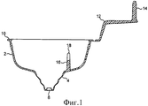
фиг.1 изображает продольный разрез первого варианта выполнения предложенного вкладыша в состоянии «сразу после формования»;figure 1 depicts a longitudinal section of a first embodiment of the proposed liner in the state "immediately after molding";
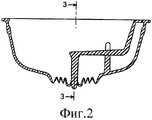
фиг.2 изображает разрез вкладыша, показанного на фиг.1, в рабочей конфигурации;figure 2 depicts a section of the liner shown in figure 1, in a working configuration;
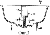
фиг.3 изображает продольный разрез вкладыша по линии 3-3, показанной на фиг.2, который дополнительно показывает возможную его модификацию;figure 3 depicts a longitudinal section of the liner along the line 3-3 shown in figure 2, which additionally shows its possible modification;
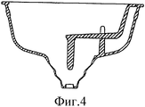
фиг.4 изображает вид, аналогичный виду, показанному на фиг.1 и 2, иллюстрирующий вкладыш после выталкивания его содержимого в контейнер;figure 4 depicts a view similar to the view shown in figures 1 and 2, illustrating the liner after pushing its contents into the container;
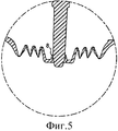
фиг.5 изображает частичный вид в увеличенном масштабе, иллюстрирующий клапанный палец, расположенный в проточном отверстии;5 is a partial enlarged view illustrating a valve pin located in a flow hole;
фиг.6 изображает вид, аналогичный виду, показанному на фиг.3, иллюстрирующий колпачок контейнера, содержащий предложенный вкладыш.Fig.6 is a view similar to that shown in Fig.3, illustrating the cap of the container containing the proposed liner.
Вкладыш, показанный на фиг.1-5, представляет собой сплошную отливку из полипропилена или подобного материала. Однако он также может быть выполнен штамповкой или прессованием из металлической фольги или из композитного материала, содержащего металл и пластмассу. Когда вкладыш извлекают из пресс-формы, он имеет конфигурацию, показанную на фиг.1. Вкладыш содержит в целом чашеобразный элемент 2 с открытым верхом, в основании которого находится свисающее углубление 4. Кольцевая стенка углубления 4, проходящая с наклоном вниз и внутрь, выполнена с множеством разнесенных кольцевых линий с низкой прочностью, то есть линий с уменьшенной толщиной, назначение которых рассмотрено в дальнейшем. В основании углубления 4 выполнено проточное отверстие 6, ограниченное упругой кромкой 8, показанной на фиг.5. Заодно с верхним периферическим краем вкладыша выполнен периферический фланец 10, от которого отходит, по существу, вбок отформованный заодно с ним один конец удлиненного связующего звена 12. За одно целое со свободным концом звена 12 выполнен палец 14, который проходит вертикально вверх в положении, которое он занимает «сразу после формования». Заодно с основанием чашеобразного элемента 2 отформована выступающая вверх опора 16, проходящая радиально наружу от углубления 4. Опора 16 содержит проходящую вверх перегородку, на двух концах верхней поверхности которой имеются соответствующие проходящие вверх ушки 18, промежуток между которыми по существу равен ширине звена 12. Таким образом, опора 16 на верхнем конце имеет по существу прямоугольный паз, ограниченный внутренними кромками двух ушек 18. Однако необходимость в этой опоре может отсутствовать, и соответственно ее может не быть.The liner shown in FIGS. 1-5 is a continuous cast of polypropylene or the like. However, it can also be made by stamping or pressing from a metal foil or from a composite material containing metal and plastic. When the liner is removed from the mold, it has the configuration shown in figure 1. The insert contains a generally cup-
Путем приложения направленной вверх силы к нижнему концу углубления 6 вкладыш приводят в рабочее состояние, что вызывает сморщивание кольцевых стенок углубления 4, то есть образование смежных сгибов противоположных направлений вокруг кольцевых линий с низкой прочностью. При этом углубление 4 перемещается вверх по существу до уровня остальной части основания чашеобразной части 2. До или вслед за этим звено 12 поворачивают на 180° против часовой стрелки, если смотреть на фиг.1, пока оно не достигнет положения, показанного на фиг.2. Свободный конец пальца, который в этом случае имеет форму усеченного конуса, вводят в отверстие 6, ограниченное проходящей вверх кромкой 8. Внутренний диаметр кромки 8 и наружный диаметр пальца 14 так подогнаны друг к другу, что палец 14 растягивает кромку 8 в наружном направлении, при этом кромка 8 входит в контакт с поверхностью пальца 14 и образует с ним по существу газонепроницаемое уплотнение. В этом положении звено 12 опирается на верхнюю поверхность опоры 16, а его боковое перемещение ограничено ушками 18.By applying an upward force to the lower end of the recess 6, the liner is brought into working condition, which causes wrinkling of the annular walls of the
Затем вкладыш частично заполняют необходимым веществом, в жидкой или порошкообразной форме, и в данном случае предполагается, что это вещество является одним из компонентов двухкомпонентной фармацевтической композиции, которую вводят в виде смеси, однако которая в смешанном состоянии является неустойчивой в течение длительного срока. Затем вкладыш герметизируют посредством присоединения к верхней поверхности его верхнего периферического фланца 10 герметизирующей пленки 20, предпочтительно из металлизированной пластмассы, поскольку такие композитные материалы является непроницаемыми как для жидкостей, так и для паров. Теперь данный вкладыш готов для использования.Then the liner is partially filled with the necessary substance, in liquid or powder form, and in this case it is assumed that this substance is one of the components of a two-component pharmaceutical composition, which is administered in the form of a mixture, but which in a mixed state is unstable for a long time. The liner is then sealed by attaching to the upper surface of its upper peripheral flange 10 a sealing
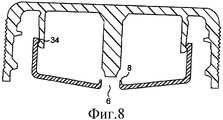
До помещения вкладыша в контейнер существует опасность неосторожного нанесения удара или приложения другой силы к незащищенному концу пальца, что может привести к утечке или даже полной потере содержимого вкладыша. Для сведения к минимуму возникновения такой опасности можно внести небольшое изменение в конструкцию, как показано только на фиг.3. Данное изменение заключается в наличии кольцевого выступа 40 на наружной части вкладыша, выполненного с ним за одно целое и проходящего вокруг незащищенного конца пальца 14 вниз до места, расположенного ниже конца пальца. Этот выступ, вместо которого может быть выполнен ряд отдельных выступов, будет защищать конец пальца от ударов.Prior to inserting the insert into the container, there is a danger of inadvertently striking or applying another force to the unprotected end of the finger, which can lead to leakage or even complete loss of the contents of the insert. To minimize the occurrence of such a hazard, you can make a small change in the design, as shown only in figure 3. This change consists in the presence of an annular protrusion 40 on the outer part of the liner, made with it in one piece and passing around the unprotected end of the
Данный вкладыш может быть использован различными способами, однако, в самом простом виде его помещают в горловину предназначенного для двух компонентов контейнера, который уже содержит другой компонент вышерассмотренной двухкомпонентной фармацевтической композиции, при этом периферический фланец 10 вкладыша опирается на край контейнера. В контейнер перед размещением на его краю вкладыша вводят несколько капель жидкого азота, а затем быстро прикладывают наружную герметизирующую крышку, прежде чем испарится весь азот. Первоначальное испарение жидкого азота заполнит пространство над продуктом контейнера азотом с замещением всего атмосферного воздуха и любых содержащихся в контейнере бактерий. Последующее испарение азота, которое будет происходить после закрытия крышки, повышает давление в пространстве над продуктом до уровня, превышающего атмосферное давление. По мере увеличения давления кромка 8 будет подаваться в наружном направлении с открытием небольшого канала для просачивания газа во внутреннюю часть вкладыша. Соответственно, давление во внутренней части вкладыша со временем достигнет значения, по существу, равного значению давления в пространстве над продуктом в контейнере.This insert can be used in various ways, however, in its simplest form, it is placed in the neck of a container intended for two components, which already contains another component of the above two-component pharmaceutical composition, with the
При необходимости введения двухкомпонентной фармацевтической композиции крышку контейнера удаляют. При этом происходит мгновенная разгерметизация пространства над продуктом в контейнере. Однако клапан, образованный взаимодействием кромки 8 с пальцем 14, представляет собой однонаправленный клапан благодаря расположению кромки 8. Таким образом, во внутренней части вкладыша не происходит мгновенной разгерметизации и соответственно по стенке углубления 4 создается существенный перепад давлений. Это обстоятельство приводит к мгновенному перемещению углубления вниз, сопровождаемому одновременным распрямлением различных сгибов в его кольцевой стенке, которое происходит на противоположных сторонах смежных сгибов. По мере перемещения нижней части углубления вниз край 8 проточного отверстия 6 будет выходить из контакта с пальцем 14, который остается неподвижным. На этом этапе проточное отверстие 6 открывается, и сверхатмосферное давление, преобладающее во внутренней части вкладыша над расположенным в нем фармацевтическим компонентом, быстро выталкивает фармацевтический компонент через отверстие 6 в контейнер, в котором он смешивается с фармацевтическим компонентом, уже находящимся в контейнере, с помощью перемешивающего воздействия, вызываемого высокоскоростной струей, проходящей через отверстие 6.If necessary, the introduction of a two-component pharmaceutical composition, the lid of the container is removed. In this case, an instant depressurization of the space above the product in the container occurs. However, the valve formed by the interaction of the
Размеры углубления и уровень заполнения контейнера могут обеспечивать расположение отверстия 6 ниже уровня жидкости в контейнере, хотя это не является существенным. Теперь вкладыш имеет конфигурацию, показанную на фиг.4, и может быть выброшен, а двухкомпонентная фармацевтическая композиция может быть введена пациенту.The dimensions of the recess and the level of filling of the container can provide the location of the hole 6 below the liquid level in the container, although this is not essential. Now the liner has the configuration shown in figure 4, and can be discarded, and a two-component pharmaceutical composition can be introduced to the patient.
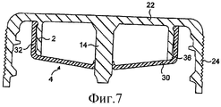
Как было описано выше, предлагаемый вкладыш и укупорочное средство или крышка присоединяются к контейнеру раздельно. Однако более удобным может быть выполнение вкладыша с крышкой за одно целое, и подобная конструкция показана на фиг.6. Подобная единая конструкция может содержать вкладыш, показанный на фиг.1-5, прикрепленный внутри крышки, например, посредством плотной посадки или клеевым способом или подобным им. Однако необходимо, чтобы эта крышка имела закрывающую пластину, обозначенную на фиг.6 позицией 22, которая проходит поверх отверстия в контейнере, а также периферическую юбку 24 с винтовой резьбой или подобной ей (не показана), если контейнер представляет собой контейнер обычного типа с выдающим отверстием, выполненным в горловине. Наличие закрывающей пластины 22 позволяет не использовать уплотняющую пленку 20, функцию которой будет выполнять пластина 22, прикрепленная с созданием уплотнения любым подходящим способом к верхнему фланцу 10 вкладыша.As described above, the proposed liner and closure or lid are attached to the container separately. However, it may be more convenient to perform the liner with the lid in one piece, and a similar design is shown in Fig.6. Such a single structure may comprise an insert as shown in FIGS. 1-5 attached inside the cover, for example by means of a snug fit or by an adhesive method or the like. However, it is necessary that this cover has a cover plate, indicated in FIG. 6 by 22, which extends over the opening in the container, as well as a
Следует понимать, что вышеописанные вкладыш и крышка предназначены для использования с контейнером, предназначенным для двух компонентов, то есть с контейнером, в котором один компонент находится в корпусе контейнера, а второй компонент, который должен быть смешан с ним, находится во вкладыше. Однако предлагаемые вкладыш и крышка также могут использоваться для контейнеров, содержащих три или более различных компонентов, которые должны быть смешаны незадолго до использования или введения лекарства. Таким образом, в видоизмененном варианте выполнения, который не показан на чертежах, вкладыш предназначен для использования с контейнером, содержащим три различных компонента. Основание чашеобразного элемента 2 выполнено с двумя рядами кольцевых, предпочтительно концентрических, линий сгибов из противоположных рядов, причем соответствующее выпускное отверстие расположено внутри каждого ряда линий сгибов. Внутренняя часть емкости, ограниченная вкладышем, разделена на два отделения перегородкой, которая выполнена за одно целое со стенкой и основанием вкладыша и проходит между двумя рядами линий сгибов, посредством чего каждое из отделений сообщается с соответствующим проточным отверстием. Кроме того, за одно целое с чашеобразным элементом выполнены два пальца и звена, по существу такие же, что показаны на фиг.1-6, которые взаимодействуют с соответствующими проточными отверстиями. Следует понимать, что при использовании два отделения заполняют различными компонентами и что работа данного вкладыша по существу аналогична вышеописанной работе, с единственным отличием, которое заключается в том, что когда контейнер открывают, оба проточных отверстия перемещаются вниз и соответственно выходят из контакта с соответствующими пальцами, посредством чего два проточных отверстия открываются по существу одновременно, и содержимое двух отделений выталкивается в корпус контейнера по существу одновременно и смешивается с третьим компонентом, уже находящимся в корпусе контейнера.It should be understood that the above liner and lid are intended for use with a container intended for two components, that is, with a container in which one component is located in the container body and the second component, which must be mixed with it, is in the liner. However, the proposed liner and lid can also be used for containers containing three or more different components that must be mixed shortly before use or administration of the drug. Thus, in a modified embodiment, which is not shown in the drawings, the liner is intended for use with a container containing three different components. The base of the cup-shaped
Claims (9)
Applications Claiming Priority (2)
| Application Number | Priority Date | Filing Date | Title |
|---|---|---|---|
| GB0601018.5 | 2006-01-18 | ||
| GB0601018A GB0601018D0 (en) | 2006-01-18 | 2006-01-18 | Inserts for multiple component containers |
Publications (2)
| Publication Number | Publication Date |
|---|---|
| RU2008131903A RU2008131903A (en) | 2010-02-27 |
| RU2410306C2 true RU2410306C2 (en) | 2011-01-27 |
Family
ID=36010533
Family Applications (1)
| Application Number | Title | Priority Date | Filing Date |
|---|---|---|---|
| RU2008131903A RU2410306C2 (en) | 2006-01-18 | 2006-10-25 | Liner for containers designed for multiple components |
Country Status (14)
| Country | Link |
|---|---|
| US (1) | US20070163898A1 (en) |
| EP (1) | EP1973799B1 (en) |
| JP (1) | JP5101524B2 (en) |
| KR (1) | KR101319796B1 (en) |
| CN (1) | CN101360658B (en) |
| AU (1) | AU2006335995B2 (en) |
| BR (1) | BRPI0621191A2 (en) |
| CA (1) | CA2637746A1 (en) |
| GB (1) | GB0601018D0 (en) |
| HK (1) | HK1122254A1 (en) |
| RU (1) | RU2410306C2 (en) |
| TW (1) | TWI392629B (en) |
| UA (1) | UA92928C2 (en) |
| WO (1) | WO2007083074A1 (en) |
Families Citing this family (6)
| Publication number | Priority date | Publication date | Assignee | Title |
|---|---|---|---|---|
| WO2008012499A1 (en) * | 2006-07-26 | 2008-01-31 | Carbonite Corporation | Inserts for multiple component containers |
| US8141730B2 (en) * | 2006-11-14 | 2012-03-27 | Carbonite Corporation | Closures for multiple component containers |
| EP2129593B1 (en) * | 2007-02-20 | 2015-12-09 | Jeong-Min Lee | Cap assembly having storage chamber for secondary material with movable working member |
| US8142827B2 (en) | 2008-04-16 | 2012-03-27 | Georgia Crown Distributing Co. | Packaged bottle beverage having an ingredient release closure with improved additive release and method and apparatus thereof |
| GB2501755B (en) * | 2012-05-04 | 2016-02-17 | Dewan Syed Ahsanur Reza | A storing and mixing device |
| DE102015118053A1 (en) * | 2015-10-22 | 2017-04-27 | Rpc Bramlage Gmbh | Closure device for a container |
Family Cites Families (20)
| Publication number | Priority date | Publication date | Assignee | Title |
|---|---|---|---|---|
| US2764983A (en) * | 1953-03-20 | 1956-10-02 | Barasch Hans Pius | Dual compartment mixing vial |
| US2753990A (en) * | 1953-07-02 | 1956-07-10 | Chalfin Philip | Container |
| DE1432098A1 (en) * | 1961-05-17 | 1969-10-09 | Bross Dipl Ing Helmut | Automatic closure with a safety device for containers with a deformable wall |
| US3337039A (en) * | 1963-05-27 | 1967-08-22 | Union Carbide Corp | Fluid storage mixing and dispensing containers |
| US3743520A (en) * | 1971-09-03 | 1973-07-03 | J Croner | Compartmented beverage container |
| US4634003A (en) * | 1984-08-22 | 1987-01-06 | Suntory Limited | Container for accommodating two kinds of liquids |
| IE70665B1 (en) * | 1989-11-22 | 1996-12-11 | Whitbread & Co Plc | Carbonated beverage container |
| GB9316317D0 (en) | 1993-08-06 | 1993-09-22 | Smithkline Beecham Plc | Novel container |
| GB9405295D0 (en) * | 1994-03-17 | 1994-04-27 | Ryford Ltd | Insert |
| GB9408800D0 (en) * | 1994-05-04 | 1994-06-22 | Scottish & Newcastle Plc | Method of pressurising inserts |
| JPH08164939A (en) * | 1995-06-01 | 1996-06-25 | Whitbread Plc | Sealed container and container filling method |
| AU5840696A (en) * | 1995-06-01 | 1996-12-18 | Whitbread Plc | Beverage container |
| GB2303363B (en) * | 1995-07-20 | 1999-10-27 | Able Ind Ltd | Pressurisable beverage vessels |
| US6390292B2 (en) * | 1997-06-11 | 2002-05-21 | Carlton And United Breweries Limited | Container for separately storing flowable materials but allowing mixing of materials when required |
| ATE287367T1 (en) * | 1997-06-11 | 2005-02-15 | Carlton & United Breweries | CONTAINER FOR SEPARATELY CONTAINED FLOWABLE MASSES AND MIXING THESE MASSES AS REQUIRED |
| GB0126692D0 (en) | 2001-11-07 | 2002-01-02 | Britvic Soft Drinks Ltd | Improvements in or relating to beverages |
| ES2201892B1 (en) * | 2001-12-20 | 2005-05-16 | Rosa Elena Serra Galdos | COMPLEX PACKING SYSTEM. |
| CN1500705A (en) * | 2002-11-18 | 2004-06-02 | 牧田正行 | Bottle cap of containing cavity with materials and pressure gas |
| US6935493B2 (en) * | 2003-04-12 | 2005-08-30 | Young Kook Cho | Cap device for mixing different kinds of materials separately contained therein and in bottle |
| CN2630165Y (en) * | 2003-07-25 | 2004-08-04 | 徐莉莉 | Container device with separate storage structure |
-
2006
- 2006-01-18 GB GB0601018A patent/GB0601018D0/en not_active Ceased
- 2006-07-12 US US11/456,929 patent/US20070163898A1/en not_active Abandoned
- 2006-10-25 RU RU2008131903A patent/RU2410306C2/en not_active IP Right Cessation
- 2006-10-25 CA CA 2637746 patent/CA2637746A1/en not_active Abandoned
- 2006-10-25 BR BRPI0621191-7A patent/BRPI0621191A2/en not_active IP Right Cessation
- 2006-10-25 UA UAA200809309A patent/UA92928C2/en unknown
- 2006-10-25 KR KR1020087019271A patent/KR101319796B1/en not_active IP Right Cessation
- 2006-10-25 JP JP2008550826A patent/JP5101524B2/en not_active Expired - Fee Related
- 2006-10-25 AU AU2006335995A patent/AU2006335995B2/en not_active Ceased
- 2006-10-25 WO PCT/GB2006/003991 patent/WO2007083074A1/en active Application Filing
- 2006-10-25 CN CN2006800514259A patent/CN101360658B/en not_active Expired - Fee Related
- 2006-10-25 EP EP20060794910 patent/EP1973799B1/en not_active Not-in-force
- 2006-10-26 TW TW95139619A patent/TWI392629B/en not_active IP Right Cessation
-
2008
- 2008-10-03 HK HK08111064A patent/HK1122254A1/en not_active IP Right Cessation
Also Published As
| Publication number | Publication date |
|---|---|
| EP1973799A1 (en) | 2008-10-01 |
| BRPI0621191A2 (en) | 2011-12-06 |
| RU2008131903A (en) | 2010-02-27 |
| HK1122254A1 (en) | 2009-05-15 |
| TWI392629B (en) | 2013-04-11 |
| KR20080094677A (en) | 2008-10-23 |
| GB0601018D0 (en) | 2006-03-01 |
| EP1973799B1 (en) | 2013-07-03 |
| TW200728162A (en) | 2007-08-01 |
| US20070163898A1 (en) | 2007-07-19 |
| CN101360658A (en) | 2009-02-04 |
| AU2006335995B2 (en) | 2011-11-03 |
| WO2007083074A1 (en) | 2007-07-26 |
| JP5101524B2 (en) | 2012-12-19 |
| KR101319796B1 (en) | 2013-10-17 |
| CN101360658B (en) | 2010-05-19 |
| CA2637746A1 (en) | 2007-07-26 |
| JP2009523666A (en) | 2009-06-25 |
| UA92928C2 (en) | 2010-12-27 |
| AU2006335995A1 (en) | 2007-07-26 |
Similar Documents
| Publication | Publication Date | Title |
|---|---|---|
| AU2007246847B2 (en) | Container closure having means for introducing an additive into the contents of the container | |
| EP2086853B1 (en) | Dispensing caps for beverage containers | |
| US20090321286A1 (en) | Container closure having a lifting cap for introducing an additive into the contents of the container | |
| RU2505465C2 (en) | Dispensing container | |
| US4834271A (en) | One-piece dispensing closure | |
| RU2410306C2 (en) | Liner for containers designed for multiple components | |
| US20080073382A1 (en) | Closure and container neck | |
| US9365335B2 (en) | Closure cap for a container | |
| US4778087A (en) | Dispensing package | |
| JP5009988B2 (en) | Insert for multi-component containers | |
| US20070295740A1 (en) | Inserts For Multiple Component Containers | |
| EP2081843B1 (en) | Closures for multiple component containers | |
| CN112810997A (en) | Hanging plug type sealing and spring push-open type container sealing device, packaging container and application thereof |
Legal Events
| Date | Code | Title | Description |
|---|---|---|---|
| MM4A | The patent is invalid due to non-payment of fees |
Effective date: 20141026 |