RU2409503C1 - Aircraft wing - Google Patents
Aircraft wing Download PDFInfo
- Publication number
- RU2409503C1 RU2409503C1 RU2009140051/11A RU2009140051A RU2409503C1 RU 2409503 C1 RU2409503 C1 RU 2409503C1 RU 2009140051/11 A RU2009140051/11 A RU 2009140051/11A RU 2009140051 A RU2009140051 A RU 2009140051A RU 2409503 C1 RU2409503 C1 RU 2409503C1
- Authority
- RU
- Russia
- Prior art keywords
- wing
- skin
- aircraft
- dividers
- flap
- Prior art date
Links
- 239000000126 substance Substances 0.000 abstract 1
- 238000013459 approach Methods 0.000 description 1
- 230000000630 rising effect Effects 0.000 description 1
Images
Landscapes
- Emergency Lowering Means (AREA)
Abstract
Description
Изобретение относится к авиации. Как известно, подъемную силу самолету создают крылья.The invention relates to aviation. As you know, the wings create an airplane’s lift.
Известно крыло самолета по книге «Проектирование конструкций самолетов» издания «Машиностроение» за 1987 г., авторы - Е.С.Войт, А.И.Ендогур, З.А.Малик-Саркисян, И.М.Алявдин. Конструкция крыла показана на рис.П24 стр.403 и состоит из внутреннего несущего каркаса, верхней и нижней обшивок, закрылков и элерона. Крыло имеет аэродинамический профиль. К недостаткам данного крыла можно отнести большое лобовое сопротивление и небольшую подъемную силу.The aircraft wing is known from the book "Designing Aircraft Structures" of the Engineering Edition for 1987; authors are E.S. Voit, A.I. Endogur, Z.A. Malik-Sargsyan, I.M. Alyavdin. The wing structure is shown in Fig. P24 p. 403 and consists of an internal supporting frame, upper and lower skins, flaps and ailerons. The wing has an aerodynamic profile. The disadvantages of this wing include a large drag and a small lift.
Известен самолет по патенту РФ 2190557. Крыло данного самолета выполнено в виде пластины равномерной толщины по профилю и заостренной спереди.Known aircraft according to the patent of the Russian Federation 2190557. The wing of this aircraft is made in the form of a plate of uniform thickness along the profile and pointed in front.
Конструкция его состоит из внутреннего несущего каркаса, верхней и нижней обшивок, закрылка и элерона. Нижняя обшивка крыла ровная и гладкая, а верхняя обшивка крыла выполняется волнистой. Подъемная сила данного крыла образуется в результате того, что воздушный поток на передней кромке крыла разделяется на верхний и нижний. Путь воздуха на верхней, волнистой поверхности длиннее, чем на нижней, ровной поверхности, в результате чего давление на нижней обшивке больше, чем на верхней. Разность этих давлений и создает подъемную силу. Недостатки данного крыла - большая собственная масса, большое лобовое сопротивление и небольшая подъемная сила.Its design consists of an internal supporting frame, upper and lower skins, flap and aileron. The lower wing skin is even and smooth, and the upper wing skin is wavy. The lifting force of this wing is formed as a result of the fact that the air flow at the leading edge of the wing is divided into upper and lower. The air path on the upper, undulating surface is longer than on the lower, even surface, as a result of which the pressure on the lower skin is greater than on the upper. The difference in these pressures creates lift. The disadvantages of this wing are its large dead weight, high drag and low lift.
Цель изобретения - создание крыла самолета нового типа, отличительного от крыльев аэродинамического и волнистого профилей, но способного создавать подъемную силу.The purpose of the invention is the creation of a wing of a new type of aircraft, distinctive from the wings of the aerodynamic and wavy profiles, but capable of creating lift.
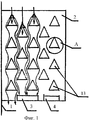
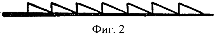
Поставленная цель достигается тем, что предлагаемое крыло выполняется в виде прямоугольной пластины в плане равномерной толщины по профилю, заостренной спереди, и конструкция его состоит из несущего внутреннего каркаса, верхней и нижней обшивок, закрылка и элерона. Нижняя обшивка выполняется ровной и гладкой. На верхней обшивке устанавливаются рассекатели, каждый из которых образован горбами и седловиной. Они производят рассечение воздушного потока на отдельные струи. Пройдя несколько рассекателей, воздушные струи увеличивают скорость и приобретают зигзагообразную форму движения. Путь зигзагообразных струй на верхней обшивке крыла длиннее, чем путь сплошного воздушного потока, движущегося по нижней обшивке крыла.This goal is achieved by the fact that the proposed wing is made in the form of a rectangular plate in terms of uniform thickness along a profile pointed at the front, and its design consists of a supporting inner frame, upper and lower skin, flap and aileron. The lower skin is flat and smooth. Dividers are installed on the upper skin, each of which is formed by humps and a saddle. They cut the air stream into separate jets. Having passed several dividers, air jets increase speed and acquire a zigzag form of movement. The path of the zigzag jets on the upper wing skin is longer than the path of a continuous air stream moving along the lower skin of the wing.
Так как скорость движения воздушных струй на верхней обшивке крыла значительно больше, чем скорость движения нижнего потолка, то давление на верхней обшивке значительно меньше давления на нижней обшивке. Разность этих давлений и является подъемной силой крыла.Since the speed of movement of air jets on the upper wing skin is much greater than the speed of movement of the lower ceiling, the pressure on the upper skin is much less than the pressure on the lower skin. The difference in these pressures is the lifting force of the wing.
Отличительные признаки заявленного изобретения от изобретения по патенту РФ 2190557.Distinctive features of the claimed invention from the invention according to the patent of the Russian Federation 2190557.
1. На верхней обшивке крыла крепятся рассекатели, каждый из которых образован горбами и седловиной. У крыла по патенту РФ 2190557 верхняя обшивка выполняется волнистой.1. On the upper skin of the wing are mounted dividers, each of which is formed by humps and a saddle. The wing according to the patent of the Russian Federation 2190557 the upper skin is wavy.
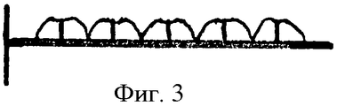
2. Воздушный поток на верхней обшивке крыла рассекателями разделяется на отдельные струи, которые обтекают их и справа, и слева и поднимаются вверх от обшивки. У крыла по патенту РФ 2190557 воздушный поток на верхней обшивке движется волнообразно.2. The air flow on the upper wing skin by dividers is divided into separate jets, which flow around them both on the right and on the left and rise upwards from the skin. At the wing according to the patent of the Russian Federation 2190557, the air flow on the upper skin moves in waves.
3. Устанавливать крыло на фюзеляж нужно под некоторым углом атаки. В патенте РФ 2190557 крыло на фюзеляже устанавливается под нулевым углом атаки. 3. You need to install the wing on the fuselage at a certain angle of attack. In the patent of the Russian Federation 2190557, the wing on the fuselage is installed at a zero angle of attack.
Предлагаемое крыло иллюстрируется чертежами.The proposed wing is illustrated by drawings.
На Фиг.1 показан вид крыла сверху.Figure 1 shows a top view of the wing.
На Фиг.2 - вид крыла сбоку.Figure 2 is a side view of the wing.
На Фиг.3 - вид крыла сзади.Figure 3 is a rear view of the wing.
На Фиг.4 показан узел «А».Figure 4 shows the node "A".
Конструкция крыла включает:The wing design includes:
1 - фюзеляж,1 - fuselage
2 - крыло,2 - wing
3 - закрылок,3 - flap
4 - элерон,4 - aileron,
5 - несущая конструкция,5 - supporting structure,
6 - нижняя обшивка,6 - lower skin
7 - верхняя обшивка,7 - upper skin,
8 - горб,8 - hump,
9 - седловина,9 - saddle,
10 - левая струя,10 - left stream,
11 - правая струя,11 - the right stream,
12 - струя, поднимающаяся вверх,12 - jet rising up
13 - рассекатели.13 - dividers.
Работа крыла.Wing work.
После команды «Взлет» самолет начинает разбег. Воздушный поток подходит к передней кромке крыла и разделяется на верхний и нижний. Нижний поток без препятствий общей массой проходит под нижней обшивкой крыла. Верхний поток, пройдя заостренную кромку, начинает движение над верхней обшивкой и попадает на рассекатели 13. Функция рассекателей заключается в том, что они рассекают воздушный поток на отдельные струи 10, 11, 12. Струи 10 и 11 обтекают горбы 8 рассекателя и слева, и справа, а струя 12 поднимается по седловине 9 вверх. Струи 10, 11, 12, двигаясь между рассекателями, приобретают зигзагообразную форму движения, увеличивают скорость и проходят путь от передней кромки крыла до закрылка, больший, чем путь проходящего по прямой воздушного потока снизу. Над верхней обшивкой крыла давление становится значительно меньше, чем на нижней обшивке. Разность между нижним и верхним давлениями и создает подъемную силу крыла.After the “Take-off” command, the aircraft begins to take off. Airflow approaches the leading edge of the wing and is divided into upper and lower. The lower flow without obstacles with a total mass passes under the lower skin of the wing. The upper stream, having passed the pointed edge, begins to move above the upper casing and falls on the
ЛитератураLiterature
1. Войт Е.С., Ендогур А.И., Малик-Саркисян З.А., Алявдин И.М. Проектирование конструкций самолетов. М.: Машиностроение. 1987 г.1. Voight E.S., Endogur A.I., Malik-Sargsyan Z.A., Alyavdin I.M. Design of aircraft structures. M .: Engineering. 1987 year
2. Патент РФ 2190557.2. RF patent 2190557.
Claims (1)
Priority Applications (1)
| Application Number | Priority Date | Filing Date | Title |
|---|---|---|---|
| RU2009140051/11A RU2409503C1 (en) | 2009-10-29 | 2009-10-29 | Aircraft wing |
Applications Claiming Priority (1)
| Application Number | Priority Date | Filing Date | Title |
|---|---|---|---|
| RU2009140051/11A RU2409503C1 (en) | 2009-10-29 | 2009-10-29 | Aircraft wing |
Publications (1)
| Publication Number | Publication Date |
|---|---|
| RU2409503C1 true RU2409503C1 (en) | 2011-01-20 |
Family
ID=46307598
Family Applications (1)
| Application Number | Title | Priority Date | Filing Date |
|---|---|---|---|
| RU2009140051/11A RU2409503C1 (en) | 2009-10-29 | 2009-10-29 | Aircraft wing |
Country Status (1)
| Country | Link |
|---|---|
| RU (1) | RU2409503C1 (en) |
Cited By (2)
| Publication number | Priority date | Publication date | Assignee | Title |
|---|---|---|---|---|
| RU2465172C1 (en) * | 2011-05-16 | 2012-10-27 | Владимир Васильевич Ликсудеев | Aircraft wing |
| RU2551829C2 (en) * | 2013-03-26 | 2015-05-27 | Владимир Васильевич Ликсудеев | Aircraft wing |
Citations (3)
| Publication number | Priority date | Publication date | Assignee | Title |
|---|---|---|---|---|
| GB718498A (en) * | 1950-10-24 | 1954-11-17 | Arthur Veryan Stephens | Improvements in and relating to solid/fluid boundary surfaces |
| US4284302A (en) * | 1979-06-11 | 1981-08-18 | Drews Hilbert F P | Driven craft having surface means for increasing propulsion efficiencies |
| RU2190557C2 (en) * | 2000-06-21 | 2002-10-10 | Григорчук Владимир Степанович | Aircraft with plate-type wing |
-
2009
- 2009-10-29 RU RU2009140051/11A patent/RU2409503C1/en not_active IP Right Cessation
Patent Citations (3)
| Publication number | Priority date | Publication date | Assignee | Title |
|---|---|---|---|---|
| GB718498A (en) * | 1950-10-24 | 1954-11-17 | Arthur Veryan Stephens | Improvements in and relating to solid/fluid boundary surfaces |
| US4284302A (en) * | 1979-06-11 | 1981-08-18 | Drews Hilbert F P | Driven craft having surface means for increasing propulsion efficiencies |
| RU2190557C2 (en) * | 2000-06-21 | 2002-10-10 | Григорчук Владимир Степанович | Aircraft with plate-type wing |
Cited By (2)
| Publication number | Priority date | Publication date | Assignee | Title |
|---|---|---|---|---|
| RU2465172C1 (en) * | 2011-05-16 | 2012-10-27 | Владимир Васильевич Ликсудеев | Aircraft wing |
| RU2551829C2 (en) * | 2013-03-26 | 2015-05-27 | Владимир Васильевич Ликсудеев | Aircraft wing |
Similar Documents
| Publication | Publication Date | Title |
|---|---|---|
| CN101323371B (en) | Lift augmenter with united jet flow structure on wing flap | |
| ES2370756T3 (en) | METHOD AND APPLIANCE TO IMPROVE MOTOR LIFTING IN AN AIRCRAFT. | |
| RU2012121848A (en) | LAMINAR FLOW WING OPTIMIZED FOR A SUPERSONIC AND HIGH SURFACE CRUISE AIRCRAFT FLIGHT | |
| JP2013508225A5 (en) | ||
| US20170073062A1 (en) | Variable Geometry Wingtip | |
| Jensch et al. | Design aspects of a gapless high-lift system with active blowing | |
| RU2409503C1 (en) | Aircraft wing | |
| EP3263454B1 (en) | Vtol aircraft with a thrust-to-weight ratio smaller than 0.1 | |
| US10919618B2 (en) | Fluid flow control for an aerofoil | |
| US20160122006A1 (en) | Low drag turbulence generators for aircraft wings | |
| US8382040B2 (en) | Hamilton H.N2 laminar flow diskette wing | |
| US2631794A (en) | Airfoil nose flap arrangement | |
| RU2623370C1 (en) | Vertical takeoff and landing aircraft implemented according to canard configuration | |
| US20170050719A1 (en) | Aerodynamic device | |
| RU2465172C1 (en) | Aircraft wing | |
| RU2508228C1 (en) | Method of aircraft airfoil boundary layer control and device for realising it | |
| RU2533771C2 (en) | Aircraft wing | |
| RU2551829C2 (en) | Aircraft wing | |
| CN113460285B (en) | High lift device for fixed wing aircraft and manufacturing method thereof | |
| Makgantai et al. | A review on wingtip devices for reducing induced drag on fixed-wing drones | |
| RU2254266C1 (en) | Aircraft wing | |
| RU2604951C1 (en) | Short takeoff and landing aircraft | |
| RU2452662C1 (en) | Biplane | |
| RU2601093C1 (en) | Aircraft wing | |
| RU149950U1 (en) | BOUNDARY LAYER WING |
Legal Events
| Date | Code | Title | Description |
|---|---|---|---|
| MM4A | The patent is invalid due to non-payment of fees |
Effective date: 20111030 |