RU2408461C2 - Method of producing reinforced cellular materials and three-layer structural material - Google Patents
Method of producing reinforced cellular materials and three-layer structural material Download PDFInfo
- Publication number
- RU2408461C2 RU2408461C2 RU2007148330/12A RU2007148330A RU2408461C2 RU 2408461 C2 RU2408461 C2 RU 2408461C2 RU 2007148330/12 A RU2007148330/12 A RU 2007148330/12A RU 2007148330 A RU2007148330 A RU 2007148330A RU 2408461 C2 RU2408461 C2 RU 2408461C2
- Authority
- RU
- Russia
- Prior art keywords
- hole
- cellular material
- fibers
- bundle
- fiber bundle
- Prior art date
Links
Images


Classifications
-
- B—PERFORMING OPERATIONS; TRANSPORTING
- B29—WORKING OF PLASTICS; WORKING OF SUBSTANCES IN A PLASTIC STATE IN GENERAL
- B29C—SHAPING OR JOINING OF PLASTICS; SHAPING OF MATERIAL IN A PLASTIC STATE, NOT OTHERWISE PROVIDED FOR; AFTER-TREATMENT OF THE SHAPED PRODUCTS, e.g. REPAIRING
- B29C44/00—Shaping by internal pressure generated in the material, e.g. swelling or foaming ; Producing porous or cellular expanded plastics articles
- B29C44/34—Auxiliary operations
- B29C44/56—After-treatment of articles, e.g. for altering the shape
-
- B—PERFORMING OPERATIONS; TRANSPORTING
- B29—WORKING OF PLASTICS; WORKING OF SUBSTANCES IN A PLASTIC STATE IN GENERAL
- B29C—SHAPING OR JOINING OF PLASTICS; SHAPING OF MATERIAL IN A PLASTIC STATE, NOT OTHERWISE PROVIDED FOR; AFTER-TREATMENT OF THE SHAPED PRODUCTS, e.g. REPAIRING
- B29C70/00—Shaping composites, i.e. plastics material comprising reinforcements, fillers or preformed parts, e.g. inserts
- B29C70/04—Shaping composites, i.e. plastics material comprising reinforcements, fillers or preformed parts, e.g. inserts comprising reinforcements only, e.g. self-reinforcing plastics
- B29C70/06—Fibrous reinforcements only
- B29C70/08—Fibrous reinforcements only comprising combinations of different forms of fibrous reinforcements incorporated in matrix material, forming one or more layers, and with or without non-reinforced layers
- B29C70/086—Fibrous reinforcements only comprising combinations of different forms of fibrous reinforcements incorporated in matrix material, forming one or more layers, and with or without non-reinforced layers and with one or more layers of pure plastics material, e.g. foam layers
-
- B—PERFORMING OPERATIONS; TRANSPORTING
- B29—WORKING OF PLASTICS; WORKING OF SUBSTANCES IN A PLASTIC STATE IN GENERAL
- B29C—SHAPING OR JOINING OF PLASTICS; SHAPING OF MATERIAL IN A PLASTIC STATE, NOT OTHERWISE PROVIDED FOR; AFTER-TREATMENT OF THE SHAPED PRODUCTS, e.g. REPAIRING
- B29C70/00—Shaping composites, i.e. plastics material comprising reinforcements, fillers or preformed parts, e.g. inserts
- B29C70/04—Shaping composites, i.e. plastics material comprising reinforcements, fillers or preformed parts, e.g. inserts comprising reinforcements only, e.g. self-reinforcing plastics
- B29C70/06—Fibrous reinforcements only
- B29C70/10—Fibrous reinforcements only characterised by the structure of fibrous reinforcements, e.g. hollow fibres
- B29C70/16—Fibrous reinforcements only characterised by the structure of fibrous reinforcements, e.g. hollow fibres using fibres of substantial or continuous length
- B29C70/24—Fibrous reinforcements only characterised by the structure of fibrous reinforcements, e.g. hollow fibres using fibres of substantial or continuous length oriented in at least three directions forming a three dimensional structure
-
- B—PERFORMING OPERATIONS; TRANSPORTING
- B29—WORKING OF PLASTICS; WORKING OF SUBSTANCES IN A PLASTIC STATE IN GENERAL
- B29L—INDEXING SCHEME ASSOCIATED WITH SUBCLASS B29C, RELATING TO PARTICULAR ARTICLES
- B29L2031/00—Other particular articles
- B29L2031/30—Vehicles, e.g. ships or aircraft, or body parts thereof
- B29L2031/3076—Aircrafts
-
- Y—GENERAL TAGGING OF NEW TECHNOLOGICAL DEVELOPMENTS; GENERAL TAGGING OF CROSS-SECTIONAL TECHNOLOGIES SPANNING OVER SEVERAL SECTIONS OF THE IPC; TECHNICAL SUBJECTS COVERED BY FORMER USPC CROSS-REFERENCE ART COLLECTIONS [XRACs] AND DIGESTS
- Y02—TECHNOLOGIES OR APPLICATIONS FOR MITIGATION OR ADAPTATION AGAINST CLIMATE CHANGE
- Y02T—CLIMATE CHANGE MITIGATION TECHNOLOGIES RELATED TO TRANSPORTATION
- Y02T50/00—Aeronautics or air transport
- Y02T50/40—Weight reduction
-
- Y—GENERAL TAGGING OF NEW TECHNOLOGICAL DEVELOPMENTS; GENERAL TAGGING OF CROSS-SECTIONAL TECHNOLOGIES SPANNING OVER SEVERAL SECTIONS OF THE IPC; TECHNICAL SUBJECTS COVERED BY FORMER USPC CROSS-REFERENCE ART COLLECTIONS [XRACs] AND DIGESTS
- Y10—TECHNICAL SUBJECTS COVERED BY FORMER USPC
- Y10T—TECHNICAL SUBJECTS COVERED BY FORMER US CLASSIFICATION
- Y10T428/00—Stock material or miscellaneous articles
- Y10T428/24—Structurally defined web or sheet [e.g., overall dimension, etc.]
- Y10T428/24033—Structurally defined web or sheet [e.g., overall dimension, etc.] including stitching and discrete fastener[s], coating or bond
Abstract
Description
Область техникиTechnical field
Настоящее изобретение относится к области композитных материалов. Более конкретно изобретение относится к способу изготовления армированного ячеистого материала. Изобретение также относится к трехслойному конструктивному элементу, средний слой которого состоит из армированного ячеистого материала, а также к летательному аппарату, в котором используется такой трехслойный конструктивный элемент, изготовленный в соответствии с предлагаемым в изобретении способом.The present invention relates to the field of composite materials. More specifically, the invention relates to a method for manufacturing a reinforced cellular material. The invention also relates to a three-layer structural element, the middle layer of which consists of a reinforced cellular material, as well as to an aircraft that uses such a three-layer structural element, manufactured in accordance with the proposed invention.
Предпосылки создания изобретенияBACKGROUND OF THE INVENTION
Благодаря своему превосходному отношению жесткости или прочности к плотности композитные материалы, в особенности трехслойные структуры, широко используются в самолетостроении. Трехслойные изделия обычно состоят из верхнего и нижнего покрывающих слоев, между которыми размещается сотовая структура, состоящая из вертикальных ячеек с шестиугольным поперечным сечением, которые обеспечивают увеличение жесткости конструктивного элемента.Due to their excellent ratio of stiffness or strength to density, composite materials, especially three-layer structures, are widely used in aircraft construction. Three-layer products usually consist of upper and lower covering layers, between which is placed a honeycomb structure consisting of vertical cells with a hexagonal cross section, which provide an increase in the rigidity of the structural element.
Трехслойные структуры также обладают и другими свойствами, например, шумоизоляционными или термоизоляционными свойствами (так называемые многофункциональные свойства), если структура выполнена соответствующим образом. Таким образом, можно обойтись без дополнительных мероприятий, которые реализуются с помощью отдельных компонентов, то есть достигается снижение веса всей конструкции.Three-layer structures also have other properties, for example, noise-insulating or heat-insulating properties (the so-called multifunctional properties), if the structure is made accordingly. Thus, it is possible to do without additional measures that are implemented using individual components, that is, the weight loss of the entire structure is achieved.
Жесткие ячеистые материалы используются в качестве альтернативы компонентам, имеющим сотовую структуру. По сравнению с сотовыми структурами жесткие ячеистые материалы обладают определенными преимуществами в отношении термоизоляционных и шумоизоляционных свойств, а также в отношении их производства. Однако ячеистые трехслойные структуры, изготовленные на основе вспененных материалов, имеют один недостаток по сравнению с сотовыми трехслойными структурами, имеющими одинаковую плотность, связанный с ожидаемым ухудшением механических характеристик. Это ухудшение может быть скомпенсировано за счет использования технологий сшивания материалов, при которых в компоненты, изготовленные из жестких ячеистых материалов, вводятся волокна или нити. После пропитки смолой зоны, пронизанные волокнами, обеспечивают увеличение механической прочности ячеистого материала.Rigid cellular materials are used as an alternative to honeycomb components. Compared to honeycomb structures, rigid cellular materials have certain advantages in terms of thermal insulation and noise insulation properties, as well as in relation to their production. However, cellular three-layer structures made on the basis of foamed materials have one drawback compared to cellular three-layer structures having the same density, associated with the expected deterioration in mechanical characteristics. This deterioration can be offset by the use of crosslinking technologies in which fibers or filaments are introduced into components made from rigid cellular materials. After resin impregnation, the zones penetrated by the fibers provide an increase in the mechanical strength of the cellular material.
Известная трехслойная структура, армированная путем прошивания материала, описана, например, в патенте США №6187411. Для того чтобы усилить эту трехслойную конструкцию, ее прошивают нитью в процессе двухстороннего сшивания, причем верхняя нить вводится иглой в слоистый материал через один покрывающий слой с использованием известных технологий и удерживается нижней нитью в слоистом материале возле другого покрывающего слоя. В результате, когда игла выводится из слоистого материала, образуется петля. Технология такого двухстороннего сшивания также описана в патенте США №4196251, в котором нижняя нить проходит параллельно второму покрывающему слою и в целом перпендикулярна верхней нити. В патенте США №5624622 также описывается трехслойная структура из ячеистых материалов, которая армирована путем прошивания, осуществляемого с использованием известной технологии петельной цепочки или сдвоенной строчки.A known three-layer structure reinforced by flashing a material is described, for example, in US Pat. No. 6,187,411. In order to strengthen this three-layer structure, it is flashed with a thread in the process of double-sided stitching, the upper thread being introduced by a needle into the layered material through one covering layer using known techniques and held by the lower thread in the layered material near the other covering layer. As a result, when the needle is withdrawn from the laminate, a loop is formed. The technology for such double-sided crosslinking is also described in US Pat. No. 4,196,251, in which the bobbin thread runs parallel to the second coating layer and is generally perpendicular to the bobbin thread. US Pat. No. 5,624,622 also describes a three-layer structure of cellular materials that is reinforced by flashing using the well-known technology of a loop chain or double stitching.
Во всех известных способах прошивания игла вводится в ячеистый материал и одновременно вводит в него нить. При прокалывании ячеистого материала нить проходит практически параллельно игле по всей длине ее хода. Поэтому размер отверстия, прокалываемого иглой, определяется диаметром иглы и толщиной нити.In all known methods of flashing, the needle is inserted into the cellular material and at the same time introduces a thread into it. When piercing the cellular material, the thread runs almost parallel to the needle along the entire length of its stroke. Therefore, the size of the hole pierced by the needle is determined by the diameter of the needle and the thickness of the thread.
Соответственно, недостатком всех этих известных способов является то, что отверстие, остающееся после выхода иглы из ячеистого материала, слишком велико по сравнению с толщиной введенной нити. Это приводит к тому, что зона отверстия, которая не заполнена волокнами, будет заполняться смолой при пропитке, так что улучшение механических характеристик в этих способах происходит не за счет волокон, что является желательным, а в основном за счет смолы. Однако улучшения некоторых механических характеристик, а именно характеристик, связанных с весом, недостаточны для получения легких конструкций, потенциально необходимых для авиационной промышленности, и поэтому использование в авиационной промышленности армированных ячеистых материалов такого типа рассматривается только в редких случаях.Accordingly, the disadvantage of all these known methods is that the hole remaining after the needle exits the cellular material is too large compared to the thickness of the inserted thread. This leads to the fact that the area of the hole, which is not filled with fibers, will be filled with resin during the impregnation, so that the improvement of mechanical characteristics in these methods does not occur due to the fibers, which is desirable, but mainly due to the resin. However, improvements in some mechanical characteristics, namely, those related to weight, are insufficient to obtain lightweight structures that are potentially necessary for the aviation industry, and therefore the use of reinforced cellular materials of this type in the aviation industry is considered only in rare cases.
Сущность изобретенияSUMMARY OF THE INVENTION
Среди прочего, целью изобретения является улучшение способа армирования ячеистых материалов волокнами или пучками волокон таким образом, чтобы улучшение механических характеристик среднего слоя, состоящего из ячеистого материала, обеспечивалось, в основном, введенными волокнами.Among other things, the aim of the invention is to improve the method of reinforcing cellular materials with fibers or bundles of fibers so that the improvement of the mechanical characteristics of the middle layer consisting of cellular material is provided mainly by the introduced fibers.
Термин "ячеистый материал", используемый в контексте настоящего изобретения, относится к любому материалу, который подходит для использования в качестве материала среднего слоя в трехслойных конструктивных элементах. Ячеистые материалы предпочтительно представляют собой действительно ячеистые материалы, однако для целей настоящего изобретения могут также использоваться текстильные материалы, например войлоки или другие нетканые материалы. Например, способ согласно изобретению также обеспечивает использование без проблем текстильных полуфабрикатов, в частности войлоков или нетканых материалов, для улучшения их характеристик. В контексте настоящего изобретения термин "пучки волокон" относится к пучкам (жгутам), состоящим из множества отдельных волокон или моноволокон, отдельных волокон, а также из нитей, которые получают скручиванием отдельных волокон или пучков волокон. В контексте настоящего изобретения термин "толщина пучка волокон" относится к сумме всех отдельных волокон пучка в сжатом состоянии.The term "cellular material", as used in the context of the present invention, refers to any material that is suitable for use as a middle layer material in three-layer structural elements. The cellular materials are preferably truly cellular materials, however, textile materials such as felts or other nonwoven materials may also be used for the purposes of the present invention. For example, the method according to the invention also provides the use without problems of textile semi-finished products, in particular felts or non-woven materials, to improve their characteristics. In the context of the present invention, the term "bundles of fibers" refers to bundles (bundles) consisting of many individual fibers or monofilaments, individual fibers, as well as threads that are obtained by twisting individual fibers or bundles of fibers. In the context of the present invention, the term “fiber bundle thickness” refers to the sum of all individual bundle fibers in a compressed state.
Цель изобретения может быть достигнута с помощью способа изготовления трехмерного армированного ячеистого материала, с помощью трехслойного конструктивного элемента, изготовленного в соответствии с таким способом, а также его применением, например, в области авиации и космонавтики, и в частности в летательных аппаратах, в которых используются такие трехслойные конструктивные элементы, изготовленные с помощью предлагаемого в изобретении способа.The purpose of the invention can be achieved using a method of manufacturing a three-dimensional reinforced cellular material, using a three-layer structural element made in accordance with this method, as well as its application, for example, in the field of aviation and astronautics, and in particular in aircraft that use such three-layer structural elements manufactured using the method of the invention.
Суть изобретения заключается в том, что в предлагаемом в нем способе исключается введение пучков волокон для армирования ячеистого материала одновременно с прокалыванием в нем отверстий, в которых в конечном счете должны быть размещены вытянутые пучки волокон, вместо этого сначала в ячеистом материале выполняются сквозные отверстия, проходящие от первой поверхности в направлении второй поверхности, а затем в них втягиваются в направлении первой поверхности пучки волокон, размещенные на другой стороне второй поверхности. Поэтому в предлагаемом в изобретении способе на первой стадии в ячеистом материале выполняется сквозное отверстие, которое проходит от первой поверхности ячеистого материала к его второй поверхности. Рассматриваемые ячеистые материалы могут иметь пространственную геометрическую форму с противолежащими поверхностями, которые параллельны друг другу только в некоторых простых случаях. Трехслойные конструкционные материалы часто характеризуются трехмерной кривизной, резкими изменениями толщины и другими изменениями геометрических параметров.The essence of the invention lies in the fact that the method proposed in it excludes the introduction of fiber bundles for reinforcing the cellular material simultaneously with piercing holes in it, in which ultimately elongated fiber bundles must be placed, instead, through holes passing through the mesh are first made from the first surface in the direction of the second surface, and then fiber bundles are placed in them in the direction of the first surface, placed on the other side of the second surface. Therefore, in the method according to the invention, at the first stage, a through hole is made in the cellular material, which extends from the first surface of the cellular material to its second surface. The cellular materials under consideration may have a spatial geometric shape with opposite surfaces that are parallel to each other only in some simple cases. Three-layer structural materials are often characterized by three-dimensional curvature, sharp changes in thickness and other changes in geometric parameters.
На другой стороне второй поверхности ячеистого материала до выполнения сквозного отверстия, в процессе его выполнения или после выполнения размещается по меньшей мере один пучок волокна. Термин "на другой стороне второй поверхности" относится к пучку волокон, размещенному ближе ко второй поверхности, чем к первой поверхности. После выполнения сквозного отверстия в ячеистом материале по меньшей мере один пучок волокон может быть захвачен со стороны сквозного отверстия для последующего втягивания этого пучка в сквозное отверстие в ячеистом материале. Иначе говоря, некоторый элемент проходит через сквозное отверстие со стороны первой поверхности ячеистого материала для захвата, удерживания и протягивания пучка волокон, размещенного на другой стороне, через сквозное отверстие в направлении первой поверхности. Указанное прохождение элемента может осуществляться одновременно с выполнением сквозного отверстия, которое может быть получено, например, путем прокалывания ячеистого материала иглой, или на следующей стадии.At the other side of the second surface of the cellular material, at least one bundle of fiber is placed before the through hole is made, during it or after it is made. The term “on the other side of the second surface” refers to a fiber bundle located closer to the second surface than to the first surface. After making a through hole in the cellular material, at least one bundle of fibers can be captured from the side of the through hole for subsequent retraction of this bundle into the through hole in the cellular material. In other words, a certain element passes through a through hole from the side of the first surface of the cellular material to capture, hold and stretch a fiber bundle placed on the other side through a through hole in the direction of the first surface. The specified passage of the element can be carried out simultaneously with the through hole, which can be obtained, for example, by piercing the cellular material with a needle, or in the next step.
Как было указано выше, могут использоваться любые ячеистые материалы, однако для авиастроения предпочтительными могут быть высококачественные жесткие материалы PMI. Естественно, также можно использовать и другие ячеистые материалы, которые состоят, например, из полихлорвинила или полиуретана. Предлагаемый в изобретении способ может использоваться для армирования не только ячеистых материалов, но также и текстильных материалов, таких как, например, войлоки или другие нетканые материалы, которые в контексте изобретения также могут быть отнесены к общему видовому термину "ячеистые материалы".As indicated above, any cellular materials may be used, however, high-quality rigid PMI materials may be preferred for aircraft manufacturing. Naturally, you can also use other cellular materials, which consist, for example, of polyvinyl chloride or polyurethane. The method according to the invention can be used for reinforcing not only cellular materials, but also textile materials, such as, for example, felts or other nonwoven materials, which in the context of the invention can also be referred to by the generic term “cellular materials”.
Сквозные отверстия могут быть выполнены в ячеистом материале под любым углом. Направление сквозных отверстий может быть выбрано индивидуально для каждого отдельного случая, в частности в зависимости от соответствующей формы ячеистого материала, который необходимо армировать, и от нагрузок, которые можно ожидать в процессе эксплуатации. Предлагаемый в изобретении способ дает возможность изготавливать трехслойные конструктивные элементы по индивидуальным заказам в зависимости от конкретного применения и ожидаемых нагрузок.Through holes can be made in the cellular material at any angle. The direction of the through holes can be selected individually for each individual case, in particular depending on the corresponding shape of the cellular material that needs to be reinforced, and on the loads that can be expected during operation. The method proposed in the invention makes it possible to produce three-layer structural elements for individual orders depending on the specific application and expected loads.
Как указывалось выше, по меньшей мере один пучок волокон обеспечивается на другой стороне второй поверхности ячеистого материала. Для того чтобы легко захватить пучок волокон, он должен удерживаться в зоне сквозного отверстия, например, в вытянутом и растянутом состоянии возле второй поверхности для обеспечения надежного захвата пучка крючком или любым другим аналогичным устройством. При захвате такого вытянутого и растянутого пучка волокон для протягивания его через сквозное отверстие он сначала складывается вдвое, так что формируется петля. В результате число моноволокон, которые в конечном счете протягиваются через сквозное отверстие, будет вдвое больше числа отдельных волокон пучка волокон в его начальном состоянии. В качестве альтернативного варианта можно заранее сформировать петлю, которая будет захвачена, так что стадия складывания пучка исключается. Используемые волоконные материалы могут состоять, например, из арамидных волокон, углеродных волокон, нейлоновых волокон, полиэфирных волокон, металлических волокон или стекловолокон, а также могут использоваться любые другие волоконные материалы. Пучки волокон часто состоят из жгутов 12К, то есть пучков волокон из 12000 моноволокон. Для того чтобы дополнительно повысить эффект армирования материала, достигаемого с пучками волокон, можно также использовать пучки с другим количеством составляющих волокон, например, пучки 24К (24000 отдельных волокон) или пучки, содержащие большее число волокон.As indicated above, at least one fiber bundle is provided on the other side of the second surface of the cellular material. In order to easily capture a bundle of fibers, it must be held in the zone of the through hole, for example, in an elongated and stretched state near the second surface to ensure reliable capture of the bundle by a hook or any other similar device. When capturing such an elongated and stretched bundle of fibers to pull it through the through hole, it first doubles up, so that a loop is formed. As a result, the number of monofilaments that ultimately extend through the through hole will be twice as many as the individual fibers of the fiber bundle in its initial state. Alternatively, a loop can be formed in advance, which will be captured, so that the stage of folding the beam is eliminated. The fiber materials used can be, for example, aramid fibers, carbon fibers, nylon fibers, polyester fibers, metal fibers or glass fibers, and any other fiber materials can also be used. Bundles of fibers often consist of 12K bundles, i.e. bundles of fibers of 12,000 monofilaments. In order to further enhance the reinforcing effect of the material achieved with fiber bundles, it is also possible to use bundles with a different number of constituent fibers, for example, 24K bundles (24,000 individual fibers) or bundles containing a larger number of fibers.
Предлагаемый в изобретении способ может обеспечить улучшение определенных механических характеристик ячеистых материалов, используемых в различных отраслях промышленности. Армированные ячеистые материалы указанного типа прежде всего используются в приложениях, для которых важно выполнение жестких требований к прочности при невысокой стоимости материала и малом весе. В качестве классического примера использования таких армированных ячеистых материалов можно привести авиацию и космонавтику, именно потому что в этом случае предъявляются высокие требования к жесткости или прочности конструктивных элементов при минимально возможном весе. Например, в аэрокосмической промышленности предлагаемый в изобретении способ может обеспечить изготовление закрылков, рулей направления или несущих конструкций фюзеляжа, а также частей облицовочных панелей или панелей внутренней отделки. Кроме того, предлагаемый в изобретении способ может также использоваться в автомобилестроении, в строительстве, в мебельной промышленности и в других отраслях промышленности, где широко используемые материалы должны удовлетворять жестким требованиям по прочности при минимально возможном весе. Предлагаемый в изобретении способ также может использоваться во всех случаях, когда важными являются не только прочностные характеристики материала, но также и характеристики по шумо- и термоизоляции, поскольку материалы, получаемые с использованием предлагаемого способа, по своей природе обладают высоким уровнем шумо- и термоизоляции.Proposed in the invention method can provide an improvement in certain mechanical characteristics of cellular materials used in various industries. Reinforced cellular materials of this type are primarily used in applications for which it is important to meet stringent strength requirements at a low cost of material and low weight. As a classic example of the use of such reinforced cellular materials, we can cite aviation and astronautics, precisely because in this case high demands are placed on the stiffness or strength of structural elements at the lowest possible weight. For example, in the aerospace industry, the method of the invention may provide for the production of flaps, rudders or supporting structures of the fuselage, as well as parts of facing panels or interior trim panels. In addition, the method according to the invention can also be used in the automotive industry, in construction, in the furniture industry and in other industries, where widely used materials must meet stringent strength requirements at the lowest possible weight. The method proposed in the invention can also be used in all cases where not only the strength characteristics of the material are important, but also the noise and thermal insulation characteristics, since the materials obtained using the proposed method, by their nature, have a high level of noise and thermal insulation.
Сквозные отверстия в ячеистом материале могут быть выполнены прокалыванием с использованием иглы со стороны первой поверхности, пока игла не выйдет из второй поверхности материала. Игла должна иметь минимально возможный диаметр, для того чтобы избежать выполнения сквозных отверстий, имеющих чрезмерный размер поперечного сечения. Размер поперечного сечения основной части иглы не должен, в частности, превышать толщину пучка волокон, который должен быть протянут через сквозное отверстие (или не должен превышать две толщины пучка волокон в исходном вытянутом состоянии).The through holes in the cellular material can be pierced using a needle from the side of the first surface until the needle comes out of the second surface of the material. The needle should have the smallest possible diameter in order to avoid making through holes with an excessive cross-sectional size. The cross-sectional size of the main part of the needle should not, in particular, exceed the thickness of the fiber bundle, which should be pulled through the through hole (or should not exceed two thicknesses of the fiber bundle in the initial elongated state).
Для захвата по меньшей мере одного пучка волокон может использоваться, например, крючок иглы. Для этой цели острие иглы может быть снабжено ушком, по периметру которого имеется разрыв с одной стороны, так что пучок волокон может быть введен в ушко в зоне острия иглы через этот боковой проем.For capturing at least one bundle of fibers, for example, a needle hook may be used. For this purpose, the needle tip can be provided with an eye, along the perimeter of which there is a gap on one side, so that a bundle of fibers can be introduced into the eye in the area of the needle tip through this side opening.
Если сквозное отверстие было выполнено с помощью иглы, которая имеет минимально возможный размер поперечного сечения, то может быть обеспечено получение сквозного отверстия, размер поперечного сечения которого меньше толщины пучка волокон, протягиваемого через это отверстие. Такой размер поперечного сечения сквозного отверстия обеспечивает возможность сжатия пучка волокон при его протягивании через отверстие, так что отдельные волокна прижимаются друг к другу настолько плотно, насколько это возможно, и проходят через отверстие максимально параллельно его внутренней стенке. Для упрощения процесса втягивания и сжатия отдельных волокон, в том месте, где соответствующий пучок волокон втягивается в ячеистый материал, можно установить воронкообразную насадку, через которую пучок волокон будет втягиваться в сквозное отверстие в материале с одновременным сжатием. Однако поскольку отдельные волокна обычно имеют круглое поперечное сечение, то остается достаточное пространство между отдельными волокнами для последующего заполнения сквозных отверстий пропитывающим материалом, в частности дюропластом, когда пучки волокон находятся в сжатом состоянии.If the through hole was made using a needle that has the smallest possible cross-sectional size, then a through hole can be obtained whose cross-sectional size is less than the thickness of the fiber bundle pulled through this hole. Such a cross-sectional size of the through hole allows the fiber bundle to be compressed when it is pulled through the hole, so that the individual fibers are pressed together as tightly as possible and pass through the hole as parallel as possible to its inner wall. To simplify the process of retracting and compressing individual fibers, at the place where the corresponding fiber bundle is pulled into the cellular material, a funnel-shaped nozzle can be installed through which the fiber bundle will be pulled into the through hole in the material with simultaneous compression. However, since individual fibers usually have a circular cross-section, there is sufficient space between the individual fibers to subsequently fill the through holes with an impregnating material, in particular duroplast, when the fiber bundles are in a compressed state.
Из предыдущих объяснений ясно, что захват-удержание пучка волокон на другой стороне второй поверхности, например, с помощью иглы, предотвращает нежелательное расширение сквозного отверстия при обратном ходе иглы. Поскольку кончик иглы входит снова в сквозное отверстие при отведении иглы назад, то игла проходит по сквозному отверстию в ячеистом материале, так что она тянет за собой по меньшей мере один пучок волокон. Поэтому пучок волокон не параллелен продольной оси иглы, когда он втягивается в сквозное отверстие, а следует за иглой и перекрывает ее в зоне острия, где игла имеет наименьшую толщину и лишь немного увеличивает толщину пучка волокон.From the previous explanations, it is clear that the capture-retention of the fiber bundle on the other side of the second surface, for example, using a needle, prevents undesirable expansion of the through hole during the reverse stroke of the needle. Since the tip of the needle enters the through hole again when the needle is retracted, the needle passes through the through hole in the cellular material, so that it pulls at least one bundle of fibers. Therefore, the fiber bundle is not parallel to the longitudinal axis of the needle when it is drawn into the through hole, but follows the needle and overlaps it in the tip area, where the needle has the smallest thickness and only slightly increases the thickness of the fiber bundle.
После того как по меньшей мере один пучок волокон протянут через сквозное отверстие указанным образом, он может быть обрезан заподлицо с первой и/или второй поверхностями. В качестве альтернативного варианта концы пучка волокон, которые выступают над поверхностями, могут быть плоско прижаты к этим поверхностям и прикреплены к ним. Если армируемый ячеистый материал входит в трехслойную структуру, то первая и/или вторая поверхности могут быть сформированы покрывающими поверхностями или покрывающими слоями трехслойной структуры. В этом случае сквозное предварительно выполняемое отверстие проходит через ячеистый материал, а также через два покрывающих слоя, которые покрывают ячеистый материал, так что пучок волокон проходит через эти три слоя. Естественно, также можно вышеописанным образом вводить пучки волокон в ячеистый материал, когда на него еще не нанесены покрывающие слои, и затем наносить на обе стороны материала покрывающие слои, причем в этом случае выступающие концы пучков волокон прижимаются и прикрепляются или приклеиваются между покрывающим слоем и ячеистым материалом.After at least one fiber bundle is pulled through the through hole in this manner, it can be cut flush with the first and / or second surfaces. Alternatively, the ends of the fiber bundle that protrude above the surfaces can be flat pressed against these surfaces and attached to them. If the reinforced cellular material is included in a three-layer structure, then the first and / or second surfaces may be formed by covering surfaces or covering layers of a three-layer structure. In this case, the through pre-formed hole passes through the cellular material, as well as through two coating layers that cover the cellular material, so that the fiber bundle passes through these three layers. Naturally, it is also possible to introduce fiber bundles into the cellular material in the manner described above, when coating layers are not yet applied to it, and then coating layers are applied to both sides of the material, in which case the protruding ends of the fiber bundles are pressed and attached or glued between the coating layer and the cellular material.
Для окончательного скрепления отдельных волокон друг с другом, а также для прикрепления волокон к ячеистому материалу сквозное отверстие, содержащее по меньшей мере один пучок волокон, может быть на следующей стадии пропитано смолой. Пропитка смолой может быть выполнена, например, путем воздействия пониженного давления на одну сторону ячеистого материала для засасывания смолы, находящейся с другой стороны, в сквозное отверстие. Также могут использоваться и любые другие известные способы пропитки.For the final bonding of individual fibers to each other, as well as for attaching the fibers to the cellular material, a through hole containing at least one bundle of fibers can be impregnated with resin in the next step. Resin impregnation can be performed, for example, by applying reduced pressure to one side of the cellular material to suck the resin on the other side into the through hole. Any other known impregnation methods may also be used.
Для армирования ячеистого материала пучками волокон с использованием вышеописанного способа необходимо многократно выполнить способ, чтобы пучки волокон были введены в ячеистый материал в различных точках. Поэтому выполнение способа начинается заново в другой точке после того, как по меньшей мере один пучок волокон будет втянут в ячеистый материал через сквозное отверстие. Вместо выполнения сквозных отверстий в разных точках ячеистого материала в соответствии с предлагаемым в изобретении способом для последовательного протягивания пучков волокон можно одновременно осуществлять способ в различных точках ячеистого материала. Например, ячеистый материал может быть одновременно проколот множеством игл, и соответствующее количество пучков волокон может размещаться на другой стороне ячеистого материала, так что они могут быть захвачены иглами и протянуты в ячеистом материале через сквозные отверстия, выполненные иглами. Также можно использовать пучки волокон, которые соединяют несколько сквозных отверстий, если процесс размещения пучков волокон сконструирован соответствующим образом.To reinforce the cellular material with fiber bundles using the above method, it is necessary to repeatedly perform the method so that the fiber bundles are introduced into the cellular material at various points. Therefore, the method starts anew at another point after at least one bundle of fibers is drawn into the cellular material through the through hole. Instead of making through holes at different points of the cellular material according to the method of the invention for sequentially pulling fiber bundles, the method can be simultaneously carried out at different points of the cellular material. For example, the cellular material can be pierced simultaneously by a plurality of needles, and an appropriate number of fiber bundles can be placed on the other side of the cellular material, so that they can be caught by the needles and drawn into the cellular material through through holes made by the needles. You can also use bundles of fibers that connect several through holes, if the process of placing bundles of fibers is designed accordingly.
В соответствии с другим вариантом осуществления настоящего изобретения его цель достигается с помощью предлагаемого в изобретении трехслойного конструктивного элемента. Предлагаемый в изобретении трехслойный конструктивный элемент содержит средний слой из ячеистого материала с противолежащими первой и второй поверхностями. Средний слой из ячеистого материала содержит множество сквозных отверстий, которые проходят между первой и второй поверхностями. В этом случае пучок волокон протягивается через каждое из таких сквозных отверстий, размеры поперечных сечений которых таковы, что отверстия практически полностью заполняются пучками волокон и используемым пропитывающим материалом. В этом случае отдельные волокна пучка волокон, проходящие через соответствующие сквозные отверстия, вытянуты по прямой линии.In accordance with another embodiment of the present invention, its purpose is achieved using the proposed in the invention three-layer structural element. Proposed in the invention three-layer structural element contains a middle layer of cellular material with opposite first and second surfaces. The middle layer of cellular material contains many through holes that extend between the first and second surfaces. In this case, the fiber bundle extends through each of such through holes, the cross-sectional dimensions of which are such that the holes are almost completely filled with fiber bundles and the impregnating material used. In this case, the individual fibers of the fiber bundle passing through the respective through holes are elongated in a straight line.
Предлагаемый в изобретении трехслойный конструктивный элемент обладает отличной прочностью или жесткостью при малом весе. Это оптимизированное отношение жесткости к весу является следствием того обстоятельства, что сквозные отверстия практически полностью заполнены пучками волокон, так что содержание смолы в этих отверстиях может поддерживаться на низком уровне.The three-layer structural element of the invention has excellent strength or stiffness with low weight. This optimized stiffness to weight ratio is a consequence of the fact that the through holes are almost completely filled with fiber bundles, so that the resin content in these holes can be kept low.
Благодаря высокой жесткости предлагаемого в изобретении трехслойного конструктивного элемента, он может быть использован в различных применениях, в которых важна жесткость материалов в сочетании с минимально возможным весом. Поэтому важным применением предлагаемого в изобретении трехслойного конструктивного элемента является аэрокосмическая промышленность, поскольку минимизация веса, естественно, является в этой отрасли наиболее важным фактором. При применении в аэрокосмической промышленности из предлагаемых в изобретении трехслойных конструктивных элементов можно изготавливать, например, закрылки, рули направления или несущие конструкции фюзеляжа, а также части облицовочных панелей или панелей внутренней отделки Другими областями применения являются, например, автомобилестроение, строительство или мебельная промышленность, а также и другие отрасли промышленности, в которых важным фактором является оптимальное соотношение между прочностью и весом.Due to the high stiffness of the proposed three-layer structural element, it can be used in various applications in which the stiffness of the materials is important in combination with the lowest possible weight. Therefore, the aerospace industry is an important application of the three-layer structural element proposed in the invention, since minimizing weight is naturally the most important factor in this industry. When used in the aerospace industry, the three-layer structural elements proposed in the invention can be used to produce, for example, flaps, rudders or supporting structures of the fuselage, as well as parts of cladding panels or interior panels. Other fields of application are, for example, automotive, construction or furniture industry, and also other industries in which an important factor is the optimal balance between strength and weight.
Предлагаемые в изобретении трехслойные конструктивные элементы в первую очередь представляют собой плоские изделия с двумя противолежащими поверхностями, которые в простейших случаях параллельны друг другу. Однако трехслойные конструктивные материалы часто характеризуются трехмерной кривизной, резкими изменениями толщины и другими изменениями геометрических параметров.The three-layer structural elements proposed in the invention are primarily flat products with two opposite surfaces, which in the simplest cases are parallel to each other. However, three-layer structural materials are often characterized by three-dimensional curvature, sharp changes in thickness and other changes in geometric parameters.
Хотя могут использоваться любые ячеистые материалы, однако для авиастроения предпочтительными могут быть высококачественные жесткие ячеистые материалы PMI. Однако также можно использовать и другие ячеистые материалы, которые состоят, например, из полихлорвинила или полиуретана. Текстильные материалы, такие как, например, войлоки или любые другие нетканые материалы также могут быть отнесены к общему видовому термину "ячеистые материалы".Although any cellular materials may be used, high-quality rigid cellular PMI materials may be preferred for aircraft manufacturing. However, you can also use other cellular materials, which consist, for example, of polyvinyl chloride or polyurethane. Textile materials such as, for example, felts or any other non-woven materials can also be referred to the generic term “cellular materials”.
Для предотвращения заполнения сквозных отверстий, выполненных в ячеистом материале, преимущественно смолой, что приводит к нежелательному увеличению веса трехслойного конструктивного элемента и одновременно к ухудшению прочностных характеристик, размер поперечного сечения сквозных отверстий должен быть меньше толщины пучков волокон, протягиваемых через эти отверстия, так что пучки волокон сжимаются при их протягивании, и размеры отверстий несколько увеличиваются. В этом случае не только можно получить низкую плотность трехслойного конструктивного элемента, но также обеспечивается расположение отдельных волокон в пучке практически по прямой линии, поскольку отдельные волокна распрямляются при выполнении процесса сжатия.To prevent filling through holes made in the cellular material, mainly resin, which leads to an undesirable increase in the weight of the three-layer structural element and at the same time to deteriorate the strength characteristics, the cross-sectional size of the through holes should be less than the thickness of the fiber bundles pulled through these holes, so that the bundles fibers are compressed when they are pulled, and the size of the holes increases slightly. In this case, not only can a low density of the three-layer structural element be obtained, but also the arrangement of the individual fibers in the bundle is ensured in a practically straight line, since the individual fibers are straightened during the compression process.
Поскольку трехслойный конструктивный элемент обычно состоит по меньшей мере из трех слоев (средний слой и два покрывающих слоя), то сквозные отверстия могут проходить непосредственно от одного покрывающего слоя к другому покрывающему слою, то есть первая и/или вторая поверхности трехслойного конструктивного элемента формируются покрывающими слоями. Соответственно, пучки волокон могут проходить через весь трехслойный конструктивный элемент, включая покрывающие слои.Since a three-layer structural element usually consists of at least three layers (the middle layer and two covering layers), through holes can pass directly from one covering layer to another covering layer, that is, the first and / or second surfaces of the three-layer structural element are formed by covering layers . Accordingly, bundles of fibers can pass through the entire three-layer structural element, including covering layers.
В зависимости от условий изготовления и рабочего режима концы пучков волокон могут либо располагаться заподлицо с первой и/или второй поверхностями, либо плоско прижимаются к ним. Соответственно, если поверхности сформированы покрывающими слоями, то концы пучков волокон либо располагаются заподлицо с покрывающими слоями, либо плоско прижимаются к их верхним поверхностям. Естественно, также возможен вариант, когда концы пучков волокон располагаются заподлицо со средним слоем из ячеистого материала или плоско прижимаются к этому слою, на обе поверхности которого могут быть нанесены покрывающие слои.Depending on the manufacturing conditions and the operating mode, the ends of the fiber bundles can either be flush with the first and / or second surfaces, or flatly pressed against them. Accordingly, if the surfaces are formed by coating layers, then the ends of the fiber bundles are either flush with the coating layers or are flat pressed to their upper surfaces. Naturally, it is also possible that the ends of the fiber bundles are flush with the middle layer of cellular material or are flat pressed to this layer, on both surfaces of which coating layers can be applied.
Из вышеприведенных объяснений, относящихся к трехслойному конструктивному элементу в соответствии с изобретением, ясно, что такой элемент может быть изготовлен с использованием предлагаемого в изобретении способа получения армированного ячеистого материала, описанного выше. Поэтому объяснения, относящиеся к предлагаемому в изобретении способу, относятся также и к трехслойному конструктивному элементу.From the above explanations related to the three-layer structural element in accordance with the invention, it is clear that such an element can be manufactured using the inventive method for producing reinforced cellular material described above. Therefore, the explanations related to the method proposed in the invention also apply to the three-layer structural element.
Краткое описание чертежейBrief Description of the Drawings
Изобретение поясняется ниже на примере предпочтительного варианта со ссылками на прилагаемые фигуры, на которых показано:The invention is illustrated below by way of example of a preferred embodiment with reference to the accompanying figures, which show:
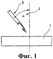
Фигура 1 - схема начального положения перед выполнением предлагаемого в изобретении способа.Figure 1 is a diagram of the initial position before the implementation of the proposed invention.
Фигура 2 - схема выполнения нескольких стадий варианта предлагаемого в изобретении способа.Figure 2 is a diagram of the implementation of several stages of the variant proposed in the invention method.
Фигура 3 - вид следующей стадии варианта предлагаемого в изобретении способа.Figure 3 is a view of the next stage of the variant proposed in the invention method.
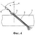
Фигура 4 - вид ячеистого материала с введенным пучком волокон.Figure 4 is a view of a cellular material with an introduced fiber bundle.
Фигура 5 - вид первого варианта армированного трехслойного конструктивного элемента.Figure 5 is a view of a first embodiment of a reinforced three-layer structural element.
Фигура 5 - вид второго варианта армированного трехслойного конструктивного элемента.Figure 5 is a view of a second embodiment of a reinforced three-layer structural element.
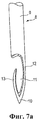
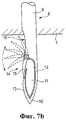
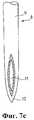
Фигуры 7а-7с - виды трех различных конструкций игл, обеспечивающих осуществление предлагаемого в изобретении способа.Figures 7a-7c are views of three different needle designs providing for the implementation of the method of the invention.
Подробное описание изобретенияDETAILED DESCRIPTION OF THE INVENTION
На фигуре 1 можно видеть изображение крючковой иглы 8 перед прокалыванием ячеистого материала 1. Крючковая игла 8, особенностью которой является зона ушка на ее конце, имеющего проем с одной стороны, описана ниже более подробно со ссылками на фигуры 7а-7с. В качестве ячеистого материала 1 может использоваться, в частности, жесткий ячеистый материал PMI или менее качественный ячеистый материал, например ячеистый ПХВ или ячеистый полиуретановый материал. Ячеистый материал 1 также может представлять собой текстильный материал, например войлок или любой другой нетканый материал. Как можно видеть на фигуре 1, игла 8 отклонена от вертикальной линии на угол α (позиция 4). Величина угла α может варьироваться от 0 до 90°, для того чтобы можно было ввести пучок волокон в ячеистый материал 1 под нужным углом. Таким образом, обеспечивается получение армирования материала "под заказ" в зависимости от применения и соответствующих нагрузок, которым ячеистый материал 1 будет подвергаться в составе трехслойной структуры. Хотя на фигуре 1 угол α показан двумерным, поскольку фигура 1 двумерна, однако понятно, что этот угол может быть также пространственным, так что отверстие, прокалываемое иглой, с проходящим сквозь это отверстие пучком волокон может быть выполнено в ячеистом материале 1 под любым нужным пространственным углом.In figure 1, you can see the image of the
На фигуре 2 изображена стадия способа, на которой кончик иглы 8 введен в ячеистый материал 1. В результате проникновения иглы в материал образуется отверстие 2, проходящее в ячеистом материале 1 под пространственным углом а. Пучок 3 волокон (например, пучок 24К), из которого сформирована петля в непосредственной близости от нижнего слоя ячеистого материала 1, располагают под материалом в зоне точки выхода иглы 8. Таким образом, эта петля пучка 3 волокон может быть захвачена и будет удерживаться крючковой иглой 8 для протягивания пучка внутрь ячеистого материала 1 при обратном ходе иглы 8.The figure 2 shows the stage of the method in which the tip of the
Хотя пучок 3 волокон для наглядности показан на фигуре 2 имеющим форму петли, однако на самом деле он может быть вытянут под нижней поверхностью ячеистого материала 1 строго параллельно этой поверхности, для того чтобы этот пучок волокон мог быть захвачен иглой 8. Пучок 3 волокон имеет толщину S, так что сложенная вдвое в петлю часть пучка волокон в соответствии с фигурой 2 имеет примерно двойную толщину 2S.Although the
Как можно видеть на фигуре 3, игла 8 выводится из ячеистого материала 1. При таком выведении пучок 3 волокон, захваченный иглой 8, вводится в сквозное отверстие 2 на нижней стороне ячеистого материала 1, причем пучок 3 волокон сжимается при введении в это отверстие. Такое сжатие происходит потому, что игла 8 и, соответственно, сквозное отверстие 2 имеют размер поперечного сечения, который меньше двойной толщины 2S пучка волокон, протягиваемого сквозь отверстие. Отдельные волокна пучка 3 волокон в целом выпрямляются и плотно прижимаются друг к другу в сквозном отверстии 2 под действием указанного сжатия и растягивающего усилия, с которым игла 8 действует на пучок волокон, так что между отдельными волокнами остаются лишь очень малые промежутки.As can be seen in figure 3, the
На фигуре 4 показано, что весь пучок 3 волокон втянут в ячеистый материал 1 под углом а, причем игла 8 уже отделилась от пучка 3 волокон. Теперь пучок 3 волокон может быть, например, отрезан заподлицо с обеими сторонами ячеистого материала 1, для того чтобы затем пропитать смолой сквозное отверстие 2.The figure 4 shows that the entire bundle of 3 fibers is pulled into the
В альтернативном варианте концы пучка 3 волокон, показанные на фигуре 4, могут быть прижаты и прикреплены к обеим поверхностям ячеистого материала 1. Прикрепление может быть осуществлено путем нанесения покрывающих слоев 7 (которые однако не показаны на фигуре 5) к обеим сторонам ячеистого материала, так что концы пучков 3 волокон плотно прижимаются и прикрепляются к поверхностям ячеистого материала 1.Alternatively, the ends of the
Вместо выполнения одного сквозного отверстия 2 в среднем слое трехслойного конструктивного элемента вышеуказанным способом для протаскивания через это отверстие пучка 3 волокон можно также дополнительно проколоть иглой 8 слои 7, как показано на фигуре 6, для того чтобы затем протянуть пучок 3 волокон через весь трехслойный конструктивный элемент 5, причем концы (6) пучка волокон могут быть также прижаты и прикреплены к покрывающим слоям 7 или отрезаны заподлицо с поверхностями этих слоев, как показано на фигуре 6.Instead of making one through
На фигурах 7а-7с представлены виды трех различных конструкций игл, обеспечивающих осуществление предлагаемого в изобретении способа. На фигуре 7а представлен вид первого варианта крючковой иглы 8 с прямой основной частью, которая суживается к острию 10 на переднем конце. В зоне острия 10 игла 8 снабжена ушком 11, которое имеет разрыв на одной стороне для введения через него пучка 3 волокон в область ушка 11 иглы 8. Поэтому зона ушка 11 крючковой иглы 8 содержит первую часть 12, которая проходит без разрывов к острию 10, и вторую выпуклую криволинейную часть 13, которая отходит от острия 10 назад в направлении основной части 9, но не доходит до нее.In figures 7a-7c presents views of three different designs of needles, providing the implementation proposed in the invention method. Figure 7a shows a view of a first embodiment of a
Конструкция крючковой иглы 8, показанная на фигуре 7b, в основном аналогична конструкции, показанной на фигуре 7а, однако содержит дополнительно запирающее устройство 14, которое предназначено для перекрытия разрыва в ушке 11 при выведении иглы из ячеистого материала 1 (обратный ход иглы). Запирающее устройство 14 по существу состоит из откидного элемента 15, который в начальном положении прилегает к основной части иглы 8 в суженной зоне 16. Как только этот откидной элемент 15 вступает во взаимодействие с ячеистым материалом 1 своим свободным концом, когда игла 8 выводится из материала, этот элемент перемещается против часовой стрелки из своего начального положения в положение запирания, когда он полностью закрывает проем в ушке 11, как показано на фигуре 7b. В этом случае предотвращается повреждение крючком второй части 13 иглы внутренней стенки сквозного отверстия 2 в ячеистом материале 1, когда из него выводится игла 8. Кроме того, запирающий механизм 14 предотвращает возможность отделения волокон от пучка 3 волокон, когда он втягивается в ячеистый материал 1. При прокалывании ячеистого материала 1, включая уже нанесенные покрывающие слои 7 или текстильного полуфабриката, запирающий механизм 14 предотвращает захватывание иглой 8 и втягивание внутрь сквозного отверстия волокон текстильного материала. Это действительно необходимо, например, при прошивании войлоков, однако в таких применениях оно может повлечь за собой ухудшение механических характеристик получаемого композитного материала.The construction of the
На фигуре 7с показан третий вариант конструкции иглы 8, в которой используется линзообразное ушко 11 в зоне ее острия. В отличие от первых двух вариантов, в которых пучок 3 волокон захватывается иглой 8 с использованием проема в периметре ушка, в этом третьем варианте пучок 3 волокон должен вводиться в ушко 11 иглы, для того чтобы он был захвачен иглой.Figure 7c shows a third embodiment of a
Claims (18)
выполнение в ячеистом материале сквозного отверстия, которое проходит от первой поверхности ячеистого материала ко второй его поверхности;
расположение по меньшей мере одного пучка волокон на другой стороне второй поверхности ячеистого материала;
проникновение через сквозное отверстие с первой поверхности для того, чтобы захватить по меньшей мере один пучок волокон; и
втягивание по меньшей мере одного пучка волокон в сквозное отверстие в ячеистом материале.1. A method of obtaining a reinforced cellular material, containing the following stages:
performing in the cellular material a through hole that extends from the first surface of the cellular material to its second surface;
the location of at least one bundle of fibers on the other side of the second surface of the cellular material;
penetration through the through hole from the first surface in order to capture at least one bundle of fibers; and
retracting at least one bundle of fibers into the through hole in the cellular material.
обрезание по меньшей мере одного пучка волокон, втянутого в сквозное отверстие, таким образом, чтобы его концы были заподлицо с первой и/или со второй поверхностями; или
размещение по меньшей мере одного пучка волокон, втянутого в сквозное отверстие, на первой и/или на второй поверхностях.6. The method according to claim 1, which further comprises the following steps:
cutting off at least one bundle of fibers drawn into the through hole so that its ends are flush with the first and / or second surfaces; or
placing at least one bundle of fibers drawn into the through hole on the first and / or second surfaces.
средний слой ячеистого материала, в котором имеется по меньшей мере одно сквозное отверстие, и по меньшей мере один пучок волокон, размещенный в этом отверстии, и находящийся в сжатом состоянии;
причем поперечное сечение сквозного отверстия имеет такой размер, что оно практически полностью заполняется по меньшей мере одним пучком волокон.10. A three-layer structural element containing:
the middle layer of cellular material in which there is at least one through hole, and at least one bundle of fibers placed in this hole, and in a compressed state;
moreover, the cross section of the through hole is so large that it is almost completely filled with at least one bundle of fibers.
Applications Claiming Priority (4)
| Application Number | Priority Date | Filing Date | Title |
|---|---|---|---|
| US68529605P | 2005-05-27 | 2005-05-27 | |
| DE102005024408.4 | 2005-05-27 | ||
| DE102005024408A DE102005024408A1 (en) | 2005-05-27 | 2005-05-27 | Producing fiber reinforced foam materials for aircraft involves engaging through hole from first surface to engage at least one fiber bundle and pulling bundle(s) into through hole in foam material |
| US60/685,296 | 2005-05-27 |
Publications (2)
| Publication Number | Publication Date |
|---|---|
| RU2007148330A RU2007148330A (en) | 2009-07-10 |
| RU2408461C2 true RU2408461C2 (en) | 2011-01-10 |
Family
ID=37387715
Family Applications (1)
| Application Number | Title | Priority Date | Filing Date |
|---|---|---|---|
| RU2007148330/12A RU2408461C2 (en) | 2005-05-27 | 2006-05-18 | Method of producing reinforced cellular materials and three-layer structural material |
Country Status (9)
| Country | Link |
|---|---|
| US (1) | US9289927B2 (en) |
| EP (1) | EP1883526B1 (en) |
| JP (1) | JP5047951B2 (en) |
| CN (1) | CN101184606B (en) |
| BR (1) | BRPI0609920A2 (en) |
| CA (1) | CA2604572C (en) |
| DE (2) | DE102005024408A1 (en) |
| RU (1) | RU2408461C2 (en) |
| WO (1) | WO2006125561A1 (en) |
Cited By (1)
| Publication number | Priority date | Publication date | Assignee | Title |
|---|---|---|---|---|
| RU2762030C2 (en) * | 2017-10-10 | 2021-12-14 | Гроц-Беккерт Коммандитгезелльшафт | Device and method for manufacturing carrying element equipped with set of fiber bundles |
Families Citing this family (62)
| Publication number | Priority date | Publication date | Assignee | Title |
|---|---|---|---|---|
| DE102005024408A1 (en) | 2005-05-27 | 2006-11-30 | Airbus Deutschland Gmbh | Producing fiber reinforced foam materials for aircraft involves engaging through hole from first surface to engage at least one fiber bundle and pulling bundle(s) into through hole in foam material |
| DE102005035681A1 (en) * | 2005-07-27 | 2007-02-08 | Röhm Gmbh | Manufacturing process for reinforcing core materials for core composites and core composite structures |
| DE102006056570B3 (en) * | 2006-11-30 | 2008-04-10 | Airbus Deutschland Gmbh | Needle for inserting fiber bundles into foam sheets, for producing insulating materials for use in aircraft, has lever which opens and closes eye, allowing fiber bundle to be inserted or removed |
| US7891096B2 (en) | 2007-01-23 | 2011-02-22 | Airbus Deutschland Gmbh | Method for reinforcing a foam material as well as a sandwich component |
| DE102007003273A1 (en) | 2007-01-23 | 2008-07-24 | Airbus Deutschland Gmbh | Localized processing of reinforced foam materials as well as composite core components |
| DE102007003274B3 (en) * | 2007-01-23 | 2008-06-19 | Airbus Deutschland Gmbh | Method e.g. for reinforcing foam material, involves providing processing area and creating processing area with laminar for partial surrounding gap and fiber-surface material is arranged into gap and has foam material |
| FR2918599B1 (en) * | 2007-07-13 | 2009-08-14 | Chomarat Composites Soc Par Ac | TEXTILE PRODUCT FOR SANDWICH STRUCTURE AND METHOD OF MANUFACTURE |
| DE102007033869A1 (en) | 2007-07-20 | 2009-01-29 | Eads Deutschland Gmbh | Apparatus and method for providing cut-to-length rovings and machine for reinforcing a textile semifinished product |
| DE102007051422A1 (en) | 2007-10-25 | 2009-04-30 | Evonik Röhm Gmbh | Two-sided single-needle lower thread stitching |
| DE102007055684A1 (en) * | 2007-11-21 | 2009-06-10 | Airbus Deutschland Gmbh | Device for producing a reinforced foam material |
| US8127450B2 (en) * | 2008-01-31 | 2012-03-06 | Airbus Operations Gmbh | Method for producing a sandwich construction, in particular a sandwich construction for the aeronautical and aerospace fields |
| DE102008006981B3 (en) * | 2008-01-31 | 2009-06-10 | Airbus Deutschland Gmbh | Producing a sandwich structure in air- and space flight area, comprises applying a heating material on a side of a sandwich structure material, and bringing a reinforcing element into the core structure material and the heating material |
| DE102008001826B3 (en) * | 2008-05-16 | 2009-09-17 | Airbus Deutschland Gmbh | Method for manufacturing reinforcement of recess for circularly fabric sandwich, involves braiding annular fabric core with fabric traces, and feed through is generated in fabric core before or after braiding |
| DE102008047408B4 (en) * | 2008-09-05 | 2011-08-25 | Gelbricht, Mike, 01774 | sliding board |
| US20100080980A1 (en) * | 2008-09-30 | 2010-04-01 | Mra Systems, Inc. | Molding process for core-containing composites and composites formed thereby |
| DE102009026458A1 (en) * | 2009-05-25 | 2010-12-09 | Airbus Operations Gmbh | Structural component and manufacturing method for a structural component |
| DE102009050904B4 (en) | 2009-10-27 | 2014-05-15 | Eads Deutschland Gmbh | Apparatus and method for providing a plurality of cut-to-length rovings from an endless roving and machine for reinforcing a component |
| DE102010042128A1 (en) | 2010-10-07 | 2012-04-12 | Airbus Operations Gmbh | Structural component, aerospace vehicle or process |
| FR2967080B1 (en) * | 2010-11-08 | 2012-11-16 | Rossignol Sa | SLIDING BOARD COMPRISING AN ALLEGE CORE |
| AU2011349578B2 (en) | 2010-12-23 | 2016-06-30 | Twelve, Inc. | System for mitral valve repair and replacement |
| US20150166744A1 (en) * | 2012-01-12 | 2015-06-18 | Patwin Plastics, Inc. | Fiber reinforced material |
| US20130183482A1 (en) * | 2012-01-12 | 2013-07-18 | Timothy J. Hannen | Fiber reinforced cellular pvc |
| US9579198B2 (en) | 2012-03-01 | 2017-02-28 | Twelve, Inc. | Hydraulic delivery systems for prosthetic heart valve devices and associated methods |
| EP2733061B1 (en) | 2012-11-14 | 2015-03-11 | Airbus Operations GmbH | Fastening arrangement for attaching a floor |
| DE102012023815B4 (en) | 2012-12-05 | 2016-04-28 | Airbus Operations Gmbh | Multi-needle machine and process for producing reinforced materials |
| FR3000463B1 (en) * | 2012-12-27 | 2016-02-05 | Eads Europ Aeronautic Defence | ENERGY ABSORPTION DEVICE FOR AN AIRCRAFT STRUCTURE ELEMENT |
| JP2014201727A (en) * | 2013-04-09 | 2014-10-27 | トヨタ自動車株式会社 | Production method for fiber reinforced resin material |
| DE102013111794A1 (en) | 2013-10-25 | 2015-04-30 | Airbus Defence and Space GmbH | Repeating unit, multi-needle machine and process for producing reinforced materials |
| DE102013018158A1 (en) | 2013-12-05 | 2015-06-11 | Airbus Defence and Space GmbH | Process for producing reinforced materials and material obtainable from this process |
| DE102013114253A1 (en) | 2013-12-17 | 2015-06-18 | Airbus Defence and Space GmbH | Acoustic Kabinenpaneel |
| US10336011B2 (en) | 2013-12-17 | 2019-07-02 | Daimler Ag | Method for producing a sandwich component and sandwich component |
| DE102014014961A1 (en) * | 2014-10-14 | 2016-04-14 | Airbus Defence and Space GmbH | Device and method |
| DE102014015976A1 (en) * | 2014-10-31 | 2016-05-04 | Airbus Defence and Space GmbH | Composite construction for increased durability |
| BR102014029639B1 (en) * | 2014-11-27 | 2022-08-30 | Embraer S.A. | AUTOMATED PROCESS OF MANUFACTURING FURNITURE PARTS IN AN INTEGRATED CELL FOR MANUFACTURING AND INTEGRATED CELL FOR MANUFACTURING FURNITURE PARTS |
| FR3029834B1 (en) * | 2014-12-10 | 2019-06-07 | Doyen Entreprises | PROCESS FOR INSERTING AND PLACING INDIVIDUAL YARNS THROUGH A PANEL |
| EP3237511B1 (en) * | 2014-12-22 | 2023-08-16 | Basf Se | Fibre reinforcement of anisotropic foams |
| US10543664B2 (en) | 2014-12-22 | 2020-01-28 | Basf Se | Fiber-reinforcement of blowing-agent containing foam materials |
| EP3237508B1 (en) * | 2014-12-22 | 2020-04-22 | Basf Se | Fibre reinforcement of foams made of interconnected segments |
| US20180009960A1 (en) | 2014-12-22 | 2018-01-11 | Basf Se | Fiber-reimforced molded bodies made of expanded particle foam material |
| AT517198B1 (en) | 2015-04-24 | 2021-12-15 | Facc Ag | Control surface element for an airplane |
| EP3173216B1 (en) | 2015-11-26 | 2018-04-11 | Airbus Operations GmbH | Method and needle for reinforcing cellular materials |
| PT3464438T (en) * | 2016-05-25 | 2022-09-27 | Basf Se | Fiber-reinforcement of foam materials |
| US20190168426A1 (en) * | 2016-05-25 | 2019-06-06 | Basf Se | Fibre reinforcement of reactive foam material obtained by a double strip foam method or a block foam method |
| WO2017202668A1 (en) | 2016-05-25 | 2017-11-30 | Basf Se | Fibre reinforcement of reactive foams obtained by a moulding foam method |
| DE102016209140A1 (en) | 2016-05-25 | 2017-11-30 | Airbus Operations Gmbh | Repair concept with preimpregnated pinned foam core for sandwich structural components |
| WO2017202669A1 (en) * | 2016-05-25 | 2017-11-30 | Basf Se | Fibre-reinforced foam materials |
| CN109311193B (en) * | 2016-05-25 | 2022-01-28 | 巴斯夫欧洲公司 | Assembling fiber reinforced foams |
| EP3263321B1 (en) | 2016-06-29 | 2021-07-28 | Airbus Defence and Space GmbH | Method for producing a sandwich panel with a reinforced special plastic foam core |
| US10575950B2 (en) | 2017-04-18 | 2020-03-03 | Twelve, Inc. | Hydraulic systems for delivering prosthetic heart valve devices and associated methods |
| US10646338B2 (en) | 2017-06-02 | 2020-05-12 | Twelve, Inc. | Delivery systems with telescoping capsules for deploying prosthetic heart valve devices and associated methods |
| DE102017218310A1 (en) | 2017-10-13 | 2019-04-18 | Airbus Defence and Space GmbH | Battery case, battery assembly and method of making a battery case |
| EP3501969B1 (en) | 2017-12-19 | 2020-12-09 | Airbus Defence and Space | Composite panels assembly, furniture comprising such assembly and aircraft comprising such assembly |
| US11125087B2 (en) * | 2018-01-05 | 2021-09-21 | Raytheon Technologies Corporation | Needled ceramic matrix composite cooling passages |
| EP3533599B1 (en) | 2018-02-28 | 2023-04-05 | Airbus Defence and Space GmbH | Composite panel with reinforcing pins |
| US11459085B2 (en) * | 2019-04-30 | 2022-10-04 | Textron Innovations Inc. | Energy attenuation stabilizers and methods |
| CN110015390A (en) * | 2019-05-07 | 2019-07-16 | 珠海市琛龙船厂有限公司 | A kind of connection structure and hull of metalwork and glass reinforced plastic |
| DE102019114433A1 (en) * | 2019-05-29 | 2020-12-03 | Airbus Operations Gmbh | Method and system for manufacturing a component or semi-finished product with a fiber-reinforced foam core |
| US11572162B2 (en) * | 2019-05-29 | 2023-02-07 | Lockheed Martin Corporation | Securing assembly for a rotor blade |
| FR3098444B1 (en) * | 2019-07-08 | 2021-10-01 | Soc Internationale Pour Le Commerce Et Lindustrie | A method of reinforcing a panel and a method of manufacturing a composite panel implementing such a method |
| DE102020109741A1 (en) | 2020-04-07 | 2021-10-07 | Airbus S.A.S. | Manufacturing method and manufacturing system for manufacturing a continuous fiber-reinforced component |
| JP2020192334A (en) * | 2020-07-13 | 2020-12-03 | グローブライド株式会社 | blade |
| CN112549584B (en) * | 2020-11-18 | 2022-02-01 | 武汉大学 | Variable-angle carbon fiber automatic laying system |
Family Cites Families (48)
| Publication number | Priority date | Publication date | Assignee | Title |
|---|---|---|---|---|
| US2692219A (en) * | 1951-07-05 | 1954-10-19 | Owens Corning Fiberglass Corp | Structural panel |
| DE1182034B (en) * | 1959-09-23 | 1964-11-19 | Jose Castany Ferre | Device for producing straight stitch seams |
| US3030256A (en) * | 1960-03-08 | 1962-04-17 | Rosenthal Harry | Reinforced laminated panels with foam core |
| US3328218A (en) * | 1962-04-09 | 1967-06-27 | Noyes Howard | Process of making a structural element |
| US3240176A (en) * | 1963-07-05 | 1966-03-15 | John R Morrison | Method for making simulated needlepoint embroidery |
| DE1951310A1 (en) * | 1968-10-21 | 1970-04-30 | Upjohn Co | Lightweight composite structure |
| US4206895A (en) * | 1978-03-30 | 1980-06-10 | Olez Nejat A | Loop-tension joint |
| US4196251A (en) * | 1979-04-16 | 1980-04-01 | International Harvester Company | Rigidized resinous foam core sandwich structure |
| US4506611A (en) * | 1979-10-22 | 1985-03-26 | Hitco | Three-dimensional thick fabrics and methods and apparatus for making same |
| GB2073358B (en) * | 1980-04-03 | 1983-12-14 | Shell Res Ltd | Heat-insulated hose for liquefied gases |
| US4426414A (en) * | 1982-09-08 | 1984-01-17 | Beacon Manufacturing Company | Laminated non-woven fabric |
| AU534719B3 (en) * | 1983-12-01 | 1984-02-16 | Volcano International Medical A.B. | A method of manufacturing body protectors |
| DE3508252A1 (en) * | 1985-03-08 | 1986-09-11 | Johann 2212 Brunsbüttel Götz | METHOD FOR PULLING LIGHT FIBER FIBERS THROUGH TEXTILES AND A DEVICE FOR CARRYING OUT THE METHOD |
| JPS6392769A (en) | 1986-10-07 | 1988-04-23 | 根来産業株式会社 | Tufted pile cloth |
| JPH01129294A (en) | 1987-11-16 | 1989-05-22 | Hitachi Ltd | Display device having memory type display section |
| JPH08582B2 (en) * | 1988-09-08 | 1996-01-10 | 株式会社太洋商会 | A device for feeding a group of two stacked bags to a single packaging position of a single packaging device. |
| GB9014770D0 (en) | 1990-07-03 | 1990-08-22 | Short Brothers Plc | Manufacture of a composite material |
| DE9110061U1 (en) | 1990-11-20 | 1992-04-16 | R.M.T. Glider Manufacturers Cc, Mandini, Za | |
| IT1245753B (en) * | 1991-05-29 | 1994-10-14 | Metalleido Srl | PROCEDURE FOR THE REALIZATION OF A COMPOSITE STRUCTURE WITH INTERMEDIATE THREE-DIMENSIONAL FABRIC, AND STRUCTURE REALIZED BY THE SAME PROCEDURE |
| FR2684719B1 (en) * | 1991-12-04 | 1994-02-11 | Snecma | BLADE OF TURBOMACHINE COMPRISING PLASTS OF COMPOSITE MATERIAL. |
| US5834082A (en) * | 1992-05-04 | 1998-11-10 | Webcore Technologies, Inc. | Reinforced foam cores and method and apparatus of production |
| US5466506A (en) * | 1992-10-27 | 1995-11-14 | Foster-Miller, Inc. | Translaminar reinforcement system for Z-direction reinforcement of a fiber matrix structure |
| JP3031110B2 (en) | 1993-03-18 | 2000-04-10 | 東レ株式会社 | Method and apparatus for producing preform for fiber reinforced composite material |
| CA2138775C (en) * | 1993-05-04 | 2000-03-14 | Glenn A. Freitas | Truss reinforced foam core sandwich structure |
| FR2718670B1 (en) | 1994-04-18 | 1996-06-14 | Aerospatiale | Part comprising at least one composite material covering plate and method for producing said part. |
| JPH0833406A (en) | 1994-07-23 | 1996-02-06 | Otsuka Chem Co Ltd | Natural lawn sheet structure |
| JP3070428B2 (en) * | 1995-02-08 | 2000-07-31 | 株式会社豊田自動織機製作所 | 3D fiber tissue manufacturing equipment |
| US6027798A (en) * | 1995-11-01 | 2000-02-22 | The Boeing Company | Pin-reinforced sandwich structure |
| DE69706829T2 (en) | 1996-01-30 | 2002-04-04 | Textron Systems Corp | THREE-DIMENSIONALLY REINFORCED ABLATIVE / INSULATING COMPOSITE |
| US5832594A (en) * | 1996-05-31 | 1998-11-10 | The Boeing Company | Tooling for inserting Z-pins |
| US6187411B1 (en) * | 1996-10-04 | 2001-02-13 | The Boeing Company | Stitch-reinforced sandwich panel and method of making same |
| FR2768441B1 (en) | 1997-09-15 | 1999-10-29 | Mermet Sa | EXTERIOR FACING OF BUILDING FACADE |
| US20020007897A1 (en) * | 1998-04-01 | 2002-01-24 | Gary L. Farley | Mehtod and apparatus for providing through-the-thickness reinforcements in laminated composite materials |
| JP2001007625A (en) | 1999-06-22 | 2001-01-12 | Taiei Shoko Kk | Radome for antenna and forming method |
| AU2459101A (en) * | 1999-12-28 | 2001-07-09 | Webcore Technologies, Inc. | Fiber reinforced composite cores and panels |
| JP2001246686A (en) | 2000-03-07 | 2001-09-11 | Toyota Autom Loom Works Ltd | Composite material structure |
| DE10018035A1 (en) | 2000-04-03 | 2001-10-18 | Nils Helbig | Core material for sandwich structures, in particular, light weight structures incorporates channels whose orientation, number and thickness are optimized for a particular application |
| US7105071B2 (en) * | 2001-04-06 | 2006-09-12 | Ebert Composites Corporation | Method of inserting z-axis reinforcing fibers into a composite laminate |
| US7056576B2 (en) | 2001-04-06 | 2006-06-06 | Ebert Composites, Inc. | 3D fiber elements with high moment of inertia characteristics in composite sandwich laminates |
| US20050025948A1 (en) * | 2001-04-06 | 2005-02-03 | Johnson David W. | Composite laminate reinforced with curvilinear 3-D fiber and method of making the same |
| US6645333B2 (en) * | 2001-04-06 | 2003-11-11 | Ebert Composites Corporation | Method of inserting z-axis reinforcing fibers into a composite laminate |
| US6446675B1 (en) * | 2001-07-05 | 2002-09-10 | Albany International Techniweave, Inc. | Minimum distortion 3D woven preforms |
| JP5011613B2 (en) | 2001-07-06 | 2012-08-29 | 東レ株式会社 | Preform and molding method |
| EP1438458A4 (en) * | 2001-09-28 | 2004-12-22 | Decoray Co Ltd | Optical fiber sewing machine and manufacturing method of productsproduced using it |
| ITFI20020054A1 (en) * | 2002-03-29 | 2003-09-29 | T N T Tessuti Non Tessuti S R | METHOD AND MACHINE FOR THE PRODUCTION OF A TEXTILE MANUFACTURE DECORATED WITH AN EMBROIDERY AND MANUFACTURE SO OBTAINED |
| DE10231830A1 (en) * | 2002-07-12 | 2004-01-22 | Röhm GmbH & Co. KG | Foam with compacted surface |
| DE102005024408A1 (en) | 2005-05-27 | 2006-11-30 | Airbus Deutschland Gmbh | Producing fiber reinforced foam materials for aircraft involves engaging through hole from first surface to engage at least one fiber bundle and pulling bundle(s) into through hole in foam material |
| DE102005034400B4 (en) | 2005-07-22 | 2010-09-23 | Airbus Deutschland Gmbh | Apparatus for producing a fiber preform having a virtually random surface geometry in the TFP process |
-
2005
- 2005-05-27 DE DE102005024408A patent/DE102005024408A1/en not_active Withdrawn
-
2006
- 2006-05-18 DE DE602006018902T patent/DE602006018902D1/en active Active
- 2006-05-18 RU RU2007148330/12A patent/RU2408461C2/en not_active IP Right Cessation
- 2006-05-18 EP EP06753715A patent/EP1883526B1/en active Active
- 2006-05-18 JP JP2008512738A patent/JP5047951B2/en not_active Expired - Fee Related
- 2006-05-18 BR BRPI0609920-3A patent/BRPI0609920A2/en not_active IP Right Cessation
- 2006-05-18 WO PCT/EP2006/004733 patent/WO2006125561A1/en not_active Application Discontinuation
- 2006-05-18 US US11/921,037 patent/US9289927B2/en active Active
- 2006-05-18 CA CA2604572A patent/CA2604572C/en not_active Expired - Fee Related
- 2006-05-18 CN CN2006800183345A patent/CN101184606B/en active Active
Cited By (1)
| Publication number | Priority date | Publication date | Assignee | Title |
|---|---|---|---|---|
| RU2762030C2 (en) * | 2017-10-10 | 2021-12-14 | Гроц-Беккерт Коммандитгезелльшафт | Device and method for manufacturing carrying element equipped with set of fiber bundles |
Also Published As
| Publication number | Publication date |
|---|---|
| US20090252917A1 (en) | 2009-10-08 |
| US9289927B2 (en) | 2016-03-22 |
| BRPI0609920A2 (en) | 2010-05-11 |
| EP1883526B1 (en) | 2010-12-15 |
| CA2604572C (en) | 2012-07-17 |
| JP5047951B2 (en) | 2012-10-10 |
| JP2008545551A (en) | 2008-12-18 |
| CN101184606B (en) | 2012-07-04 |
| CA2604572A1 (en) | 2006-11-30 |
| DE102005024408A1 (en) | 2006-11-30 |
| WO2006125561A1 (en) | 2006-11-30 |
| CN101184606A (en) | 2008-05-21 |
| RU2007148330A (en) | 2009-07-10 |
| DE602006018902D1 (en) | 2011-01-27 |
| EP1883526A1 (en) | 2008-02-06 |
Similar Documents
| Publication | Publication Date | Title |
|---|---|---|
| RU2408461C2 (en) | Method of producing reinforced cellular materials and three-layer structural material | |
| JP4751448B2 (en) | Manufacturing method for reinforcing core material for sandwich structure and sandwich structure | |
| US4206895A (en) | Loop-tension joint | |
| KR20100085928A (en) | Two-sided single-needle under thread stitching process | |
| CN107107490B (en) | Composite construction for increased service life | |
| US7926761B2 (en) | Mechanical part and method of manufacturing such a part | |
| US20170151729A1 (en) | Method And Needle for Reinforcing Cellular Materials | |
| EP2625029B1 (en) | Structural component, aircraft or spacecraft, and method | |
| US20150197069A1 (en) | Carrier for a vehicle interior trim part, a vehicle interior trim part, as well as a method for manufacturing a carrier | |
| US9212437B2 (en) | One-piece fiber reinforcement for a reinforced polymer combining aligned and random fiber layers | |
| US20040247845A1 (en) | Composite material-use fiber base material | |
| US9962901B2 (en) | Preform with integrated gap fillers | |
| DE102015107338A1 (en) | Composite fiber mat for producing a carrier plate of a motor vehicle component and method for its production | |
| RU2490130C2 (en) | Channel reinforcement for sandwich structures | |
| US8474573B2 (en) | Reinforced composite sandwich panel | |
| EP2509774B1 (en) | Sandwich panel and method for its manufacture | |
| KR20200066312A (en) | 3D weaving preform for omega reinforcement | |
| DE102006044009A1 (en) | Sandwich structure, useful in resin-bonded shell components, e.g. for aircraft, comprises textile sheets spaced by filler material and connected by angled threads or tufts providing high stability | |
| Potluri et al. | Stitch-bonded Sandwich Composites for Improved Performance |
Legal Events
| Date | Code | Title | Description |
|---|---|---|---|
| PD4A | Correction of name of patent owner | ||
| MM4A | The patent is invalid due to non-payment of fees |
Effective date: 20170519 |