RU2401935C2 - Device and procedure for cutting pipe of well bore - Google Patents
Device and procedure for cutting pipe of well bore Download PDFInfo
- Publication number
- RU2401935C2 RU2401935C2 RU2008146406A RU2008146406A RU2401935C2 RU 2401935 C2 RU2401935 C2 RU 2401935C2 RU 2008146406 A RU2008146406 A RU 2008146406A RU 2008146406 A RU2008146406 A RU 2008146406A RU 2401935 C2 RU2401935 C2 RU 2401935C2
- Authority
- RU
- Russia
- Prior art keywords
- pipe
- blade
- protrusion
- cutting
- tooth
- Prior art date
Links
- 238000000034 method Methods 0.000 title claims description 28
- 238000000576 coating method Methods 0.000 claims description 16
- 239000011248 coating agent Substances 0.000 claims description 11
- 238000004519 manufacturing process Methods 0.000 abstract 1
- 239000000126 substance Substances 0.000 abstract 1
- 238000004080 punching Methods 0.000 description 5
- PXHVJJICTQNCMI-UHFFFAOYSA-N Nickel Chemical compound [Ni] PXHVJJICTQNCMI-UHFFFAOYSA-N 0.000 description 4
- 230000006835 compression Effects 0.000 description 3
- 238000007906 compression Methods 0.000 description 3
- 238000010008 shearing Methods 0.000 description 3
- 239000000956 alloy Substances 0.000 description 2
- 229910045601 alloy Inorganic materials 0.000 description 2
- 239000012530 fluid Substances 0.000 description 2
- 239000000463 material Substances 0.000 description 2
- 229910052759 nickel Inorganic materials 0.000 description 2
- RTAQQCXQSZGOHL-UHFFFAOYSA-N Titanium Chemical compound [Ti] RTAQQCXQSZGOHL-UHFFFAOYSA-N 0.000 description 1
- 230000000712 assembly Effects 0.000 description 1
- 238000000429 assembly Methods 0.000 description 1
- 238000005422 blasting Methods 0.000 description 1
- 238000009833 condensation Methods 0.000 description 1
- 230000005494 condensation Effects 0.000 description 1
- 238000005516 engineering process Methods 0.000 description 1
- 230000035515 penetration Effects 0.000 description 1
- -1 polytetrafluoroethylene Polymers 0.000 description 1
- 229920001343 polytetrafluoroethylene Polymers 0.000 description 1
- 239000004810 polytetrafluoroethylene Substances 0.000 description 1
- 238000000926 separation method Methods 0.000 description 1
- 239000010936 titanium Substances 0.000 description 1
- 229910052719 titanium Inorganic materials 0.000 description 1
- 239000012808 vapor phase Substances 0.000 description 1
- 230000003313 weakening effect Effects 0.000 description 1
Images


Classifications
-
- E—FIXED CONSTRUCTIONS
- E21—EARTH DRILLING; MINING
- E21B—EARTH DRILLING, e.g. DEEP DRILLING; OBTAINING OIL, GAS, WATER, SOLUBLE OR MELTABLE MATERIALS OR A SLURRY OF MINERALS FROM WELLS
- E21B33/00—Sealing or packing boreholes or wells
- E21B33/02—Surface sealing or packing
- E21B33/03—Well heads; Setting-up thereof
- E21B33/06—Blow-out preventers, i.e. apparatus closing around a drill pipe, e.g. annular blow-out preventers
- E21B33/061—Ram-type blow-out preventers, e.g. with pivoting rams
- E21B33/062—Ram-type blow-out preventers, e.g. with pivoting rams with sliding rams
- E21B33/063—Ram-type blow-out preventers, e.g. with pivoting rams with sliding rams for shearing drill pipes
-
- Y—GENERAL TAGGING OF NEW TECHNOLOGICAL DEVELOPMENTS; GENERAL TAGGING OF CROSS-SECTIONAL TECHNOLOGIES SPANNING OVER SEVERAL SECTIONS OF THE IPC; TECHNICAL SUBJECTS COVERED BY FORMER USPC CROSS-REFERENCE ART COLLECTIONS [XRACs] AND DIGESTS
- Y10—TECHNICAL SUBJECTS COVERED BY FORMER USPC
- Y10T—TECHNICAL SUBJECTS COVERED BY FORMER US CLASSIFICATION
- Y10T428/00—Stock material or miscellaneous articles
- Y10T428/24—Structurally defined web or sheet [e.g., overall dimension, etc.]
- Y10T428/24777—Edge feature
-
- Y—GENERAL TAGGING OF NEW TECHNOLOGICAL DEVELOPMENTS; GENERAL TAGGING OF CROSS-SECTIONAL TECHNOLOGIES SPANNING OVER SEVERAL SECTIONS OF THE IPC; TECHNICAL SUBJECTS COVERED BY FORMER USPC CROSS-REFERENCE ART COLLECTIONS [XRACs] AND DIGESTS
- Y10—TECHNICAL SUBJECTS COVERED BY FORMER USPC
- Y10T—TECHNICAL SUBJECTS COVERED BY FORMER US CLASSIFICATION
- Y10T83/00—Cutting
- Y10T83/04—Processes
- Y10T83/0581—Cutting part way through from opposite sides of work
-
- Y—GENERAL TAGGING OF NEW TECHNOLOGICAL DEVELOPMENTS; GENERAL TAGGING OF CROSS-SECTIONAL TECHNOLOGIES SPANNING OVER SEVERAL SECTIONS OF THE IPC; TECHNICAL SUBJECTS COVERED BY FORMER USPC CROSS-REFERENCE ART COLLECTIONS [XRACs] AND DIGESTS
- Y10—TECHNICAL SUBJECTS COVERED BY FORMER USPC
- Y10T—TECHNICAL SUBJECTS COVERED BY FORMER US CLASSIFICATION
- Y10T83/00—Cutting
- Y10T83/04—Processes
- Y10T83/0596—Cutting wall of hollow work
-
- Y—GENERAL TAGGING OF NEW TECHNOLOGICAL DEVELOPMENTS; GENERAL TAGGING OF CROSS-SECTIONAL TECHNOLOGIES SPANNING OVER SEVERAL SECTIONS OF THE IPC; TECHNICAL SUBJECTS COVERED BY FORMER USPC CROSS-REFERENCE ART COLLECTIONS [XRACs] AND DIGESTS
- Y10—TECHNICAL SUBJECTS COVERED BY FORMER USPC
- Y10T—TECHNICAL SUBJECTS COVERED BY FORMER US CLASSIFICATION
- Y10T83/00—Cutting
- Y10T83/748—With work immobilizer
- Y10T83/7487—Means to clamp work
- Y10T83/7493—Combined with, peculiarly related to, other element
- Y10T83/75—With or to tool guide
-
- Y—GENERAL TAGGING OF NEW TECHNOLOGICAL DEVELOPMENTS; GENERAL TAGGING OF CROSS-SECTIONAL TECHNOLOGIES SPANNING OVER SEVERAL SECTIONS OF THE IPC; TECHNICAL SUBJECTS COVERED BY FORMER USPC CROSS-REFERENCE ART COLLECTIONS [XRACs] AND DIGESTS
- Y10—TECHNICAL SUBJECTS COVERED BY FORMER USPC
- Y10T—TECHNICAL SUBJECTS COVERED BY FORMER US CLASSIFICATION
- Y10T83/00—Cutting
- Y10T83/929—Tool or tool with support
- Y10T83/9411—Cutting couple type
- Y10T83/9447—Shear type
Abstract
Description
Настоящее изобретение относится к устройству для резания трубы ствола скважины, лезвию для использования в данном устройстве, противовыбросовому превентору, содержащему данное устройство, и способу разрезания трубы ствола скважины.The present invention relates to a device for cutting a wellbore pipe, a blade for use in this device, a blowout preventer containing this device, and a method for cutting a wellbore pipe.
Известно широкое разнообразие противовыбросовых превенторов и режущих лезвий для крышек противовыбросовых превенторов.A wide variety of blowout preventers and cutting blades for blowout preventer covers are known.
Обычные противовыбросовые превенторы имеют плашки с возможностью их избирательного приведения в действие в противоположно расположенных крышках, прикрепленных к основному корпусу. Плашки бывают либо трубными плашками (для контакта, сцепления и охвата трубы и/или инструментов для изоляции ствола скважины), или срезающими плашками (для контакта и физического срезания трубы, обсадной колонны, трубного или инструмента, используемого в скважинных работах). Плашки обычно устанавливаются противоположно друг другу на сторонах основного корпуса и могут, при активировании и последующем срезании трубы, уплотняться друг с другом в центре основного корпуса над центром ствола скважины.Conventional blowout preventers have dies with the ability to selectively actuate them in oppositely located covers attached to the main body. Dies are either pipe dies (for contact, grip and coverage of the pipe and / or tools for isolating the wellbore), or shear dies (for contact and physical cutting of the pipe, casing, pipe or tool used in downhole operations). Dies are usually installed opposite each other on the sides of the main body and can, when activated and subsequent cutting of the pipe, be sealed with each other in the center of the main body above the center of the wellbore.
Обычные плашки включают в себя блок плашек, на котором прикреплены части, то есть уплотнения и/или режущие лезвия.Conventional dies include a block of dies on which parts are attached, i.e. seals and / or cutting blades.
Существует необходимость в противовыбросовом превенторе, который может эффективно и успешно срезать трубы, то есть трубы, используемые в скважинных работах, включающие в себя сравнительно большие трубы, такие как обсадные трубы, утяжеленные бурильные трубы, и замки бурильной трубы. В некоторых существующих системах срезания труб замок бурильной трубы размещен так, чтобы срезающие плашки не соприкасались с замком бурильной трубы, а срезали сравнительно меньший участок трубы. Одной проблемой таких систем является то, что надлежащее размещение требует времени и, если трубный замок размещен ненадлежащим образом, результатом может быть неудачное срезание.There is a need for a blowout preventer that can efficiently and successfully cut pipes, that is, pipes used in downhole operations, including relatively large pipes, such as casing pipes, weighted drill pipes, and drill pipe locks. In some existing pipe cutting systems, the drill pipe lock is positioned so that the cutting dies do not come in contact with the drill pipe lock but cut off a relatively smaller portion of the pipe. One problem with such systems is that proper placement takes time and, if the pipe lock is not properly positioned, the result can be a bad cut.
Согласно настоящему изобретению создается устройство для резания труб ствола скважины, содержащее, по меньшей мере, одно лезвие для резания трубы, отличающееся тем, что дополнительно содержит выступ, перемещаемый при использовании для уменьшения структурной прочности упомянутой трубы в зоне, подлежащей разрезанию. Предпочтительно, выступ является перемещаемым из отведенного от трубы положения в выдвинутое положение, в котором он контактирует с трубой. Уменьшение структурной прочности может выполняться посредством повреждения (то есть вдавливанием, продавливанием, деформацией) трубы при перемещении выступа в выдвинутое положение. Выступ может иметь форму, обуславливающую такое повреждение. Зона уменьшения структурной прочности может включать в себя зону, где имеет место срезание, и/или примыкающую зону.According to the present invention, there is provided a device for cutting pipes of a borehole containing at least one blade for cutting a pipe, characterized in that it further comprises a protrusion that is moved when used to reduce the structural strength of said pipe in the area to be cut. Preferably, the protrusion is movable from a retracted position from the pipe to an extended position in which it is in contact with the pipe. A decrease in structural strength can be accomplished by damaging (i.e., pushing, forcing, deforming) the pipe when the protrusion moves to the extended position. The protrusion may take the form of causing such damage. The structural strength reduction zone may include a zone where shearing takes place and / or an adjacent zone.
Если выступ составляет единое целое и/или является частью, по меньшей мере, одного лезвия, выступ может иметь участок постепенно увеличивающейся ширины, при этом, при использовании, выступ проникает в и продавливает стенку трубы и соответствующие поверхности на противоположных сторонах участка, одновременно срезая трубу с противоположных направлений по периметру.If the protrusion is integral and / or part of at least one blade, the protrusion may have a section of gradually increasing width, while, in use, the protrusion penetrates and pushes the wall of the pipe and corresponding surfaces on opposite sides of the section, while cutting the pipe from opposite directions around the perimeter.
Дополнительные признаки устройства предложены в п.п.2-20.Additional features of the device are proposed in items 2-20.
Согласно другому аспекту настоящего изобретения для использования в устройстве, упомянутом выше, создано лезвие с любыми признаками лезвия, описанными в этом документе.According to another aspect of the present invention, for use in the apparatus mentioned above, a blade is provided with any of the features of the blade described herein.
Согласно другому аспекту настоящего изобретения создан противовыбросовый превентор, содержащий описанное выше устройство.According to another aspect of the present invention, there is provided a blowout preventer comprising the apparatus described above.
Согласно еще одному аспекту настоящего изобретения создан способ резания трубы ствола скважины, содержащий этапы (а) резания трубы ствола скважины, используя, по меньшей мере, одно лезвие, отличающийся этапом (б) использования выступа для уменьшения структурной прочности трубы в зоне, подлежащей резанию.According to yet another aspect of the present invention, there is provided a method for cutting a borehole pipe comprising the steps of: (a) cutting a pipe of a borehole using at least one blade characterized by step (b) of using a protrusion to reduce the structural strength of the pipe in the area to be cut.
Дополнительные этапы способа изложены в п.п.21-27.Additional steps of the method are described in paragraphs.21-27.
В одном аспекте настоящее изобретение раскрывает противовыбросовый превентор и способы его использования, при этом противовыбросовый превентор имеет перемещаемые блоки плашек, одна или каждая из которых имеет лезвие, выполняющее одно или несколько отверстий или продавливаний трубы, когда труба срезается, для облегчения полного срезания трубы.In one aspect, the present invention discloses a blowout preventer and methods for using it, wherein the blowout preventer has movable die blocks, one or each of which has a blade that makes one or more holes or bursts of pipe when the pipe is cut, to facilitate complete shear of the pipe.
В некоторых аспектах настоящее изобретение раскрывает противовыбросовый превентор с корпусом, имеющим верхнюю часть, нижнюю часть и отверстие в корпусе, проходящее от верхней до нижней части, и плашечное устройство, перемещаемое внутри корпуса и включающее в себя два блока плашек, каждый с лезвием.In some aspects, the present invention discloses a blowout preventer with a housing having an upper portion, a lower portion and an opening in the housing extending from the upper to the lower portion, and a ram device movable within the housing and including two die blocks, each with a blade.
В некоторых аспектах настоящее изобретение раскрывает режущее лезвие для противовыбросового превентора, имеющее один, два, три или больше выступов, зубьев или ярко выраженных участков для формирования отверстия или зоны продавливания в трубе для облегчения срезания трубы. In some aspects, the present invention discloses a cutting blade for a blowout preventer having one, two, three or more protrusions, teeth, or pronounced portions for forming an opening or a punching zone in a pipe to facilitate shearing of the pipe.
Для лучшего понимания настоящего изобретения ниже приведено подробное описание со ссылками на приложенные чертежи, на которых изображено следующее:For a better understanding of the present invention, the following is a detailed description with reference to the attached drawings, which depict the following:
фигура 1A показывает вид сбоку, частично в разрезе, первого варианта осуществления противовыбросового превентора согласно настоящему изобретению;Figure 1A shows a side view, partially in section, of a first embodiment of a blowout preventer according to the present invention;
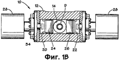
фигура 1B показывает вид в плане, частично в разрезе, противовыбросового превентора, показанного на фигуре 1A;Figure 1B shows a plan view, partially in section, of a blowout preventer shown in Figure 1A;
фигура 1C - вид сбоку, частично в разрезе, противовыбросового превентора, показанного на фигуре 1A при использовании;Figure 1C is a side view, partially in section, of a blowout preventer shown in Figure 1A in use;
фигура 2A - вид сверху в изометрии первого варианта осуществления лезвия согласно настоящему изобретению;Figure 2A is an isometric plan view of a first embodiment of a blade according to the present invention;
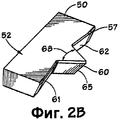
фигура 2B - вид снизу в изометрии лезвия, показанного на фигуре 2A;Figure 2B is a bottom isometric view of the blade shown in Figure 2A;
фигура 2C - вид в плане лезвия, показанного на фигуре 2A;Figure 2C is a plan view of the blade shown in Figure 2A;
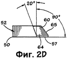
фигура 2D - вид сбоку лезвия, показанного на фигуре 2A;figure 2D is a side view of the blade shown in figure 2A;
фигура 3A - вид сверху в изометрии второго варианта осуществления лезвия согласно настоящему изобретению;Figure 3A is an isometric plan view of a second embodiment of a blade according to the present invention;
фигура 3B - вид снизу в изометрии лезвия, показанного на фигуре 3A;Figure 3B is a bottom isometric view of the blade shown in Figure 3A;
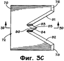
фигура 3C - вид сверху лезвия, показанного на фигуре 3A;figure 3C is a top view of the blade shown in figure 3A;
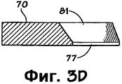
фигура 3D - вид разреза по линии 3D-3D на фигуре 3C;figure 3D is a section view along the
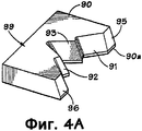
фигура 4A - вид сверху в изометрии третьего варианта осуществления лезвия согласно настоящему изобретению;Figure 4A is a top isometric view of a third embodiment of a blade according to the present invention;
фигура 4B - вид снизу в изометрии лезвия, показанного на фигуре 4A;Figure 4B is a bottom isometric view of the blade shown in Figure 4A;
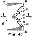
фигура 4C - вид в плане лезвия, показанного на фигуре 4A;Figure 4C is a plan view of the blade shown in Figure 4A;
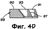
фигура 4D - вид разреза по линии 4D-4D на фигуре 4C;Figure 4D is a sectional view taken along
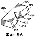
фигура 5A - вид сверху в изометрии четвертого варианта осуществления лезвия согласно настоящему изобретению;Figure 5A is a top isometric view of a fourth embodiment of a blade according to the present invention;
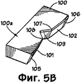
фигура 5B - вид снизу в изометрии лезвия, показанного на фигуре 5A;Figure 5B is a bottom isometric view of the blade shown in Figure 5A;
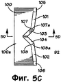
фигура 5C - вид в плане лезвия, показанного на фигуре 5A; Figure 5C is a plan view of the blade shown in Figure 5A;
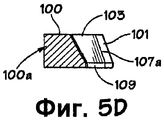
фигура 5D - вид разреза по линии 5D-5D на фигуре 5C;5D is a sectional view taken along
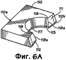
фигура 6A - вид сверху в изометрии пятого варианта осуществления лезвия согласно настоящему изобретению;Figure 6A is an isometric plan view of a fifth embodiment of a blade according to the present invention;
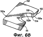
фигура 6B - вид снизу в изометрии лезвия, показанного на фигуре 6A;Figure 6B is a bottom isometric view of the blade shown in Figure 6A;
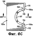
фигура 6C - вид в плане лезвия, показанного на фигуре 6A;Figure 6C is a plan view of the blade shown in Figure 6A;
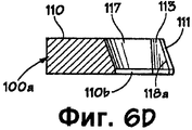
фигура 6D - вид разреза по линии 6D-6D на фигуре 6C;Figure 6D is a sectional view taken along
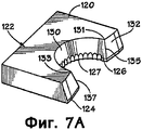
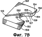
фигура 7A - вид сверху в изометрии шестого варианта осуществления лезвия согласно настоящему изобретению;Figure 7A is a top isometric view of a sixth embodiment of a blade according to the present invention;
фигура 7B - вид снизу в изометрии лезвия, показанного на фигуре 7A;Figure 7B is a bottom isometric view of the blade shown in Figure 7A;
фигура 7C - вид в плане лезвия, показанного на фигуре 7A;Figure 7C is a plan view of the blade shown in Figure 7A;
фигура 7D - вид разреза по линии 7D-7D на фигуре 7C;Figure 7D is a sectional view taken along
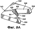
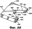
фигура 8A - вид сверху в изометрии седьмого варианта осуществления лезвия согласно настоящему изобретению;Figure 8A is a top isometric view of a seventh embodiment of a blade according to the present invention;
фигура 8B - вид снизу в изометрии лезвия, показанного на фигуре 8A;Figure 8B is a bottom isometric view of the blade shown in Figure 8A;
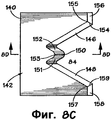
фигура 8C - вид в плане лезвия, показанного на фигуре 8A;Figure 8C is a plan view of the blade shown in Figure 8A;
фигура 8D - вид разреза по линии 8D-8D, показанной на фигуре 8C;Figure 8D is a sectional view taken along
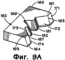
фигура 9A - вид сверху в изометрии восьмого варианта осуществления лезвия согласно настоящему изобретению;Figure 9A is a top isometric view of an eighth embodiment of a blade according to the present invention;
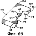
фигура 9B - вид снизу в изометрии лезвия, показанного на фигуре 9A;Figure 9B is a bottom isometric view of the blade shown in Figure 9A;
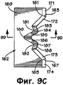
фигура 9C - вид сверху лезвия, показанного на фигуре 9A;figure 9C is a top view of the blade shown in figure 9A;
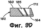
фигура 9D - вид разреза по линии 9D-9D на фигуре 9C;Figure 9D is a sectional view taken along
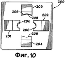
фигура 10 - схематический вид в плане второго варианта осуществления противовыбросового превентора согласно настоящему изобретению;figure 10 is a schematic plan view of a second embodiment of a blowout preventer according to the present invention;
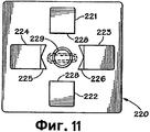
фигура 11 - схематический вид в плане третьего варианта осуществления противовыбросового превентора согласно настоящему изобретению;Figure 11 is a schematic plan view of a third embodiment of a blowout preventer according to the present invention;
фигура 12 - схематический вид сбоку, частично в разрезе, четвертого варианта осуществления противовыбросового превентора согласно настоящему изобретению;figure 12 is a schematic side view, partially in section, of a fourth embodiment of a blowout preventer according to the present invention;
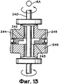
фигура 13 - схематический вид сбоку, частично в разрезе, пятого варианта осуществления противовыбросового превентора согласно настоящему изобретению;figure 13 is a schematic side view, partially in section, of a fifth embodiment of a blowout preventer according to the present invention;
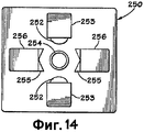
фигура 14 - схематический вид в плане шестого варианта осуществления противовыбросового превентора согласно настоящему изобретению;Figure 14 is a schematic plan view of a sixth embodiment of a blowout preventer according to the present invention;
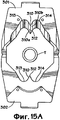
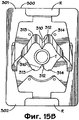
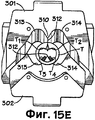
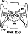
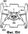
фигуры 15A-15H схематически показывают разные этапы работы противовыбросового превентора согласно настоящему изобретению для разрезания трубы.Figures 15A-15H schematically show the different steps of a blowout preventer according to the present invention for cutting a pipe.
Как показано на фигурах 1A-1C, противовыбросовый превентор 10 согласно настоящему изобретению имеет корпус 12 с вертикальным каналом 14. При использовании труба, например часть бурильной колонны D, проходит через канал 14. Корпус 12 имеет нижний фланец 16 и верхний фланец 18 для соединения противовыбросового превентора 10 в блоке устьевого оборудования. Плашечные направляющие 20 и 22 проходят наружу с противоположных сторон проходного отверстия 14. Плашечные сборки противовыбросового превентора 10 включают в себя первую и вторую плашки 24 и 26, установленные в направляющих 20 и 22 соответственно. Устройства возвратно-поступательного перемещения, такие как исполнительные механизмы 28, оборудованы для перемещения или выдвижения плашек в ответ на давление текучей среды в канале 14 для срезания участка бурильной колонны D, проходящей через канал, и для отвода плашек из проходного отверстия. Каждый исполнительный механизм 28 включает в себя поршень 30 в цилиндре 32 и шток 34, соединяющий поршень и плашку, перемещаемую им, соответствующим образом соединенные, как показано, с корпусом 12. Использовано соответствующее устройство для подачи текучей среды под давлением к противоположным сторонам поршня 30.As shown in Figures 1A-1C, the
Верхнее лезвие 36 (любое лезвие согласно настоящему изобретению) находится на плашке 24, а нижнее лезвие 38 (любое лезвие согласно настоящему изобретению) находится на плашке 26. Режущие лезвия 36 и 38 установлены так, что режущая кромка лезвия 38 проходит под режущей кромкой лезвия 36 при резании секции трубы, например бурильной колонны D.The upper blade 36 (any blade according to the present invention) is on the
Срезающее действие режущих лезвий 36 и 38 срезает бурильную колонну D (фигура 1C). Нижний участок бурильной колонны D опущен в ствол скважины (не показан) ниже противовыбросового превентора 10. По возможности (в действительности для любого способа согласно настоящему изобретению) бурильная колонна D подвешивается на нижней группе плашек.The shearing action of the
На фигурах 2A-2D показано лезвие 50, согласно настоящему изобретению, имеющее корпус 52 с основанием 57 и передней гранью 54. Передняя грань 54 имеет два наклонных участка 61, 62 и выступ 60, выступающий из передней грани 54 между двумя наклонными участками 61, 62. Кромки 56, 58 находятся на концах наклонных участков 61, 62 соответственно. Выступ 60 имеет две наклонных грани 63, 64, сходящиеся в центральной кромке 65. Угол 68 между гранями 63, 64 (что может быть верным для угла между любыми двумя выступающими гранями согласно настоящему изобретению) может быть любым необходимым углом и, в некоторых аспектах, находиться в пределах 30-90 градусов и в некоторых частных аспектах составляет 30 градусов, 60 градусов или 90 градусов.2A-2D, a
В некоторых аспектах (что является верным для любого лезвия согласно настоящему изобретению) режущие поверхности расположены с уклоном к вертикали и в одном частном аспекте, как показано на фигуре 2D, два наклонных участка 61, 62 находятся под углом 20 градусов к вертикали. В других аспектах угол для любой режущей поверхности любого лезвия согласно настоящему изобретению находится в пределах между 20 градусами и 60 градусами и в некоторых аспектах угол составляет 20 градусов, 45 градусов, или 60 градусов.In some aspects (which is true for any blade according to the present invention), the cutting surfaces are inclined to the vertical and in one particular aspect, as shown in Figure 2D, the two
На фигурах 3A-3D показано лезвие 70 согласно настоящему изобретению, имеющее корпус 72 с основанием 77, две противоположные наклонные грани 81, 82 и выступ 80 между двумя наклонными гранями 81, 82. Выступ 80 имеет две наклонных грани 83, 84, сходящиеся в центральной кромке 85. Наклонные концевые участки 76, 78 находятся на концах граней 81, 82 соответственно.Figures 3A-3D show a
На фигурах 4A-4D показано лезвие 90 согласно настоящему изобретению с корпусом 99, противоположными наклонными гранями 91, 92, противоположными наклонными гранями 93, 94 и наклонными концевыми участками 95, 96. Выступы 97, 98 сформированы между гранями 91, 93 и 94, 92 соответственно. Лезвие 90 имеет основание 90a.Figures 4A-4D show a
На фигурах 5A-5D показано лезвие 100 согласно настоящему изобретению с корпусом 100a, противоположными наклонными гранями 101, 102, противоположными наклонными гранями 103, 104 и противоположными наклонными концевыми участками 105, 106. Выступы 107, 108 сформированы между гранями 101, 103 и 104, 102 соответственно. Лезвие 100 имеет основание 109. Выступ 107 имеет кромку 107a и выступ 108 имеет кромку 108a.Figures 5A-5D show a
На фигурах 6A-6D показано лезвие 110 согласно настоящему изобретению с корпусом 110a, двумя наклонными гранями 111, 112, двумя противоположными наклонными гранями 113, 114, наклонными концевыми участками 115, 116, центральной полукруглой наклонной гранью 117 и основанием 110b. Выступы 118, 119 сформированы между гранями 111, 113 и 114, 112 соответственно. Выступ 118 имеет кромку 118a и выступ 119 имеет кромку 119a.Figures 6A-6D show a
На фигурах 7A-7D показано лезвие 120 согласно настоящему изобретению, имеющее корпус 122, основание 124, противоположные наклонные грани 126, 128, наклонные грани 132, 134, наклонные концевые участки 136, 138 и полукруглую наклонную грань 130. Зазубренная режущая поверхность 125 проходит вокруг нижней кромки 127 грани 130 и проходит частично на грани 126, 128. Зазубренная поверхность 125 имеет заостренные зубья 129, но возможно выполнение этих зубьев закругленными. Грани 126, 132 находятся под углом друг к другу, формируя выступ 131 с кромкой 135. Грани 128, 134 находятся под углом друг к другу, формируя выступ 133 с кромкой 137.Figures 7A-7D show a
На фигурах 8A-8D показано лезвие 140 согласно настоящему изобретению, имеющее корпус 142, основание 144, противоположные наклонные грани 146, 148, выступ 150 между гранями 146, 148 и наклонные концевые участки 156, 158. Выступ 150 имеет наклонные грани 151, 152 и центральную грань 153. Выступ 155 сформирован между гранями 156, 146, имеющими кромку 154. Выступ 157 сформирован между гранями 148, 158, имеющими кромку 159. Возможно, как показано, выполнение выступа 150 закругленным.Figures 8A-8D show a
На фигурах 9A-9D показано лезвие 160, согласно настоящему изобретению, имеющее корпус 162, основание 164, противоположные наклонные грани 172, 173, наклонные концевые участки 171, 174, выступы 181, 182 и выемку 180, сформированную между выступами 181, 182. Выступ 161 с кромкой 163 сформирован между гранью 172 и концевым участком 171. Выступ 165 с кромкой 167 сформирован между гранью 173 и концевым участком 174. Выступ 181 имеет наклонные грани 183, 185 и наклонный центральный участок 184. Выступ 182 имеет наклонные грани 186, 188 и наклонный центральный участок 187. Возможно, как показано, выполнение выступов 181, 182 закругленными.Figures 9A-9D show a
На фигуре 10 показано устройство 200 для разрезания трубы, например, но без ограничения этим, бурильной трубы, утяжеленной бурильной трубы, обсадной трубы, райзера морской платформы, насосно-компрессорной трубы и замков бурильной колонны, что действительно может выполняться любым устройством, показанным в данном описании согласно настоящему изобретению, и с любым лезвием или лезвиями согласно настоящему изобретению. Устройство 200 имеет две попеременно перемещаемые группы плашек 201, 202 и 203, 204. В одном аспекте каждая плашка 201, 202 имеет множество разнесенных друг от друга продавливающих зубьев (или выступов) 206, выполняющих ряд соответствующих разнесенных друг от друга отверстий в трубе, тем самым, ослабляя трубу и облегчая ее полное срезание лезвиями 208 (любым согласно настоящему изобретению или любым известным лезвием) плашек 203, 204. В некоторых аспектах имеется два, три, четыре, пять, шесть или больше зубьев и, по возможности, зубья могут наплавляться твердым сплавом или может применяться повышение твердости их материала (что верно для любого лезвия, выступа лезвия, или части лезвия, раскрытых в данном описании согласно настоящему изобретению относительно наплавления твердым сплавом и/или повышения твердости материала). Любой такой зуб или зубья могут использоваться на любом лезвии согласно настоящему изобретению и/или лезвия могут удаляться.Figure 10 shows a
На фигуре 11 показано устройство 220 согласно настоящему изобретению с двумя группами перемещаемых плашек 221, 222 и 223, 224. Плашки 221, 222 имеют плоские грани 228, используемые для сплющивания трубы 229 ("сплющивание" означает превращение в некруглую до любой степени в сравнении с первоначальной круглой формой трубы 229 и включают в себя, но не в качестве ограничения, по существу или полностью сплющенную трубу), например, как показано пунктирной линией на фигуре 11. После сплющивания труба 229 полностью разрезается лезвиями 225, 226 на плашках 223, 224 соответственно. Лезвия 225, 226 могут представлять собой любые лезвия согласно настоящему изобретению или любые известные лезвия.Figure 11 shows the
На фигуре 12 показан способ разрезания трубы 230 приложением растягивающего усилия T вдоль длины трубы посредством устройства TA приложения растягивающего усилия, показанного схематически (см. стрелки T), или приложением к ней сжимающего усилия посредством устройства CA, показаного схематически (см. стрелки C). Плашечные устройства 231, 232 с лезвиями 233, 234 соответственно противовыбросового превентора 235 являются перемещаемыми для разрезания трубы 230. 12 illustrates a method for cutting
По возможности, при двухходовой работе (или многоходовой работе) на трубу 230 действует растяжение и лезвия 233, 234 воздействуют на трубу, затем на трубу действует сжатие и лезвия 233, 234 затем полностью разрезают трубу, или наоборот. Этап или этапы растяжения и/или этап или этапы сжатия могут использоваться в любом способе согласно настоящему изобретению с включением в себя, но не ограничиваясь этим, способов, показанных на фигурах 10-15.Whenever possible, in two-way operation (or multi-way operation), the
На фигуре 13 показан способ согласно настоящему изобретению, в котором к трубе 240 прикладывается крутящий момент, в то время как она разрезается лезвиями 242, 243 (любым лезвием или лезвиями согласно настоящему изобретению) перемещаемых плашечных устройств 244, 245 противовыбросового превентора 246. Вращение трубы 240 может выполняться любым подходящим вращающим устройством, находящимся над, рядом и/или под трубой, то есть устройством RA (фигура 13). Этап или этапы приложения крутящего момента могут использоваться в любом способе согласно настоящему изобретению.Figure 13 shows a method according to the present invention, in which a torque is applied to the
На фигуре 14 показан способ согласно настоящему изобретению разрезания трубы 254 лезвиями 255 на перемещаемых плашках 256 в устройстве 250 противовыбросового превентора, использующем управляемые подрывные заряды 252 в перемещаемых деталях 253 или на них, или способ ослабления трубы в конкретных необходимых местах для облегчения полного разрезания труб лезвием (лезвиями) согласно настоящему изобретению. По возможности, заряды 252 устанавливают на режущих лезвиях 255 или на плашках 256. Один, два, три, четыре или больше зарядов могут использоваться. Может использоваться любое режущее лезвие согласно настоящему изобретению или любые известные режущие лезвия.Figure 14 shows a method according to the present invention for cutting
На фигурах 15A-15H показан способ согласно настоящему изобретению, использующий противовыбросовый превентор 300 (фигура 15B) согласно настоящему изобретению (то есть, как любой раскрытый в этом документе) с перемещаемыми плашками R с лезвиями 301, 302, при этом лезвие 301 аналогично лезвию 302, лезвие 302 - перевернутое по отношению к лезвию 301, что возможно в случае любых двух лезвий любого устройства, раскрываемого в этом документе. Каждое лезвие 301, 302 имеет корпус 304 и центральный выступ 310 с заостренной деталью 312 и режущие участки 313, 314. Каждый выступ 310 имеет режущие поверхности 310a и 310b. Режущие поверхности устроены с уклоном к вертикали, и выступы 310 имеют режущие поверхности, находящиеся под углом друг к другу. Плашки R перемещают лезвия так, что первоначально выступы 310 входят в контакт и продавливают трубу T (например, обсадную трубу, бурильную трубу, замки бурильной колонны, утяжеленную бурильную трубу, и т.п.) и затем последующее перемещение выступов в трубу T и резка трубы T выступами 310 и режущими участками 313, 314 завершает разрезание трубы T. Выступы 310 являются диаметрально противопоставленными так, чтобы их выступающие точки (и затем хвостовые части выступов) наталкивались друг на друга, облегчая продавливание и затем разрезание труб. Использование двойных противопоставленных продавливающих выступов также служит для удерживания трубы в необходимом месте в противовыбросовом превенторе 300 во время разрезания, так чтобы продавливание и разрезание осуществлялись лезвиями 301, 302, удерживаемыми в нужном месте относительно трубы T.Figures 15A-15H show a method according to the present invention using a blowout preventer 300 (figure 15B) according to the present invention (i.e., like any disclosed herein) with movable rams R with
Как показано на фигуре 15B, зубья 312 выступов 310 контактируют с внешней поверхностью трубы T. При контакте зубья 312 удерживают трубу в нужном положении. На фигуре 15C показан первоначальный вход зубьев 312 в трубу T.As shown in FIG. 15B, the
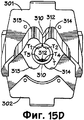
Как показано на фигуре 15D, зубья 312 прошли всю толщину стенки трубы T и разводят в стороны участки T1, T2 и T3, T4. На фигуре 15E показано дополнительное продвижение внутрь зубьев 312 и дополнительное разделение участков T1, T2 и T3, T4 трубы.As shown in FIG. 15D, the
Как показано на фигуре 15F, когда зубья 312 продвигаются внутрь и нижний зуб 312 (если смотреть на фигуру 15F) перемещается под верхний зуб 312, режущие поверхности 313 и 314 начинают резать трубу T. Выступы 310 режут объем трубы T, а режущие поверхности 313, 314 (и выступы 310, когда продвигаются через трубу) должны резать только остающийся участок трубы T для выполнения полного разрезания трубы T. В некоторых аспектах и в зависимости от величины трубы выступы 310 могут резать всю трубу.As shown in FIG. 15F, when the
Как показано на фигуре 15G, труба T является почти полностью разрезанной и верхний выступ 310 продолжает перемещение над нижним выступом 310, по мере того, как продолжается дополнительное пронизывание трубы каждым выступом, и поверхности 313, 314 продолжают дополнительно раздвигать участки T1 , T2 и участки T3, T4 трубы. На фигуре 15H показана полностью разрезанная труба T.As shown in FIG. 15G, the pipe T is almost completely cut and the
По возможности, используется только одно лезвие 301 или 302 и другое лезвие не имеет выступа или выступов.Whenever possible, only one
Как показано на разных фигурах (например, на фигурах 1A, 12, 13, 15A), в некоторых аспектах предпочтительно, чтобы одно лезвие было перевернутым по отношению к противоположному лезвию. Когда используется лезвие с центральным выступом (или два таких лезвия), режущие поверхности, примыкающие к режущему выступу, либо вообще не режут трубу, или только должны резать часть общей толщины стенки, периферию трубы (в отличие, например, от некоторых "V-срезающих" или "V-образных" лезвий уровня техники, в которых каждая режущая поверхность режет гораздо больший участок трубы).As shown in various figures (for example, in figures 1A, 12, 13, 15A), in some aspects, it is preferable that one blade is inverted with respect to the opposite blade. When a blade with a central protrusion (or two such blades) is used, the cutting surfaces adjacent to the cutting protrusion either do not cut the pipe at all, or only have to cut a part of the total wall thickness, the periphery of the pipe (unlike, for example, some “V-cutting” "or" V-shaped "blades of the prior art, in which each cutting surface cuts a much larger portion of the pipe).
Согласно варианту настоящего изобретения покрытие с низким коэффициентом трения наносится на лезвия согласно настоящему изобретению (или любые лезвия уровня техники) или его части, и/или его режущих поверхностей, и/или его верха и/или низа, и/или его части, продавливающей трубу, например, но не ограничивается этим, политетрафторэтиленового покрытия, электролизного никелевого покрытия, и/или титаново/никелевого покрытия, включающего в себя, но не ограничивающегося этим, покрытия низкого коэффициента трения, наносимые по технологии конденсации из паровой фазы. Такие покрытия показаны, например, как покрытие 69 (фигура 2A) и покрытие 209 (фигура 10) и как покрытие 79 (фигура 3A) сверху лезвия и как покрытие 75 (фигура 3A) снизу лезвия, наносимые любым подходящим способом или техническим средством. Эти покрытия могут наноситься любой известной подходящей толщины для практического применения покрытий низкого коэффициента трения.According to an embodiment of the present invention, a low friction coating is applied to the blades according to the present invention (or any prior art blades) or part thereof, and / or its cutting surfaces, and / or its top and / or bottom, and / or its part, pushing through a pipe, for example, but not limited to, a polytetrafluoroethylene coating, an electrolytic nickel coating, and / or a titanium / nickel coating, including, but not limited to, low friction coatings applied by condensation technology ation from the vapor phase. Such coatings are shown, for example, as coating 69 (Figure 2A) and coating 209 (Figure 10) and as coating 79 (Figure 3A) on top of the blade and as coating 75 (Figure 3A) on the bottom of the blade, applied by any suitable method or technical means. These coatings may be applied in any known suitable thickness for the practical use of low friction coatings.
Настоящее изобретение, таким образом, создает в некоторых, но не обязательно во всех вариантах осуществления, противовыбросовый превентор с корпусом с верхом, низом и сквозным каналом сверху донизу, плашечным устройством, перемещаемым в корпусе и включающим в себя два плашечных блока, каждый с режущим лезвием согласно настоящему изобретению.The present invention thus provides, in some, but not necessarily all embodiments, a blowout preventer with a housing with a top, bottom, and a through channel from top to bottom, a die device that moves in the body and includes two die blocks, each with a cutting blade according to the present invention.
Настоящее изобретение, таким образом, создает, по меньшей мере, в некоторых вариантах осуществления, способы использования противовыбросового превентора согласно настоящему изобретению.The present invention thus provides, in at least some embodiments, methods for using a blowout preventer according to the present invention.
Настоящее изобретение, таким образом, создает в некоторых вариантах осуществления способ разрезания трубы, применяемой для скважинных работ, заключающийся в том, что вставляют трубу в устройство для резания труб, включающее в себя первую деталь, перемещаемую к трубе, вторую деталь, перемещаемую к трубе, подлежащей разрезанию, и расположенную противоположно первой детали, первое лезвие на первой детали и содержащее корпус, первый выступ, выступающий из корпуса, первую зубчатую структуру на первом выступе для контакта с трубой и продавливания трубы, режущие поверхности на первом выступе, образующие первую зубчатую структуру для резания труб, достаточно выступающую из корпуса первого лезвия, так, чтобы первый выступ мог контактировать с трубой и продавливать ее, прежде чем любая другая часть корпуса первого лезвия войдет в контакт с трубой, и вторым лезвием на второй детали, перемещают первое лезвие к трубе для приведения первой зубчатой структуры в контакт с внешней поверхностью трубы, перемещают первое лезвие так, что первая зубчатая структура продавливает трубу и проходит сквозь трубу, перемещают первое лезвие для резания участка трубы режущими поверхностями первого выступа и разрезают трубу перемещением первого лезвия и второго лезвия по направлению друг к другу. Такой способ может включать в себя одну или несколько возможных комбинаций из следующих: использование второго лезвия устройства разрезания труб, имеющего корпус, второй выступ, выступающий из корпуса, вторую зубчатую структуру на втором выступе для вхождения в контакт с трубой и продавливания трубы, режущие поверхности на втором выступе, образующие зубчатую структуру для резания труб, и вторую зубчатую структуру, достаточно выступающую из корпуса второго лезвия, так, что второй выступ контактирует с трубой и продавливает трубу, прежде чем любая другая часть корпуса второго лезвия войдет в контакт с трубой, при этом перемещают второе лезвие к трубе, когда первое лезвие перемещают к трубе, так что вторая зубчатая структура контактирует с внешней поверхностью трубы, продавливается в трубу, проходит сквозь трубу, и перемещают второе лезвие для перерезания участка трубы режущими поверхностями второго выступа, при этом труба разрезается режущими поверхностями выступов первого лезвия и второго лезвия; первое лезвие дополнительно содержит режущие поверхности первого лезвия, примыкающие к первому выступу, и второе лезвие содержит режущие поверхности второго лезвия, примыкающие ко второму выступу, и перемещают первое лезвие и второе лезвие так, чтобы каждая режущая поверхность каждого лезвия резала участок трубы; структура первого зуба является закругленной; структура второго зуба является закругленной; на первый выступ, режущие поверхности первого лезвия, на второй выступ, режущие поверхности второго выступа наносятся покрытия с низким коэффициентом трения; на нижнюю и верхнюю поверхности первого лезвия и нижнюю и верхнюю поверхности второго лезвия нанесено покрытие с низким коэффициентом трения; первый выступ располагается над вторым выступом и напротив него; каждая из структур двух зубьев входит в контакт с трубой по существу одновременно и продавливаeт трубу по существу одновременно; во время разрезания трубы труба растягивается устройством растяжения; во время разрезания трубы труба сжимается устройством сжатия; во время разрезания трубы труба вращается устройством вращения; прежде, чем происходит любой контакт между трубой и любым из лезвий, труба сплющивается устройством сплющивания; первое лезвие имеет первый верх и первый низ, второе лезвие имеет второй верх и второй низ, режущие поверхности первого выступа устроены с уклоном от первого верха к первому низу, и режущие поверхности второго выступа устроены с уклоном от второго верха ко второму низу; при этом второе лезвие является перевернутым по отношению к первому лезвию; режущие поверхности выступов каждого лезвия находятся под углом друг к другу в пределах между 30 и 90 градусов; труба относится к группе труб, включающей в себя обсадные трубы, бурильные трубы, утяжеленные бурильные трубы и трубные замки.The present invention thus provides, in some embodiments, a method of cutting a pipe used for downhole operations, comprising inserting a pipe into a pipe cutting device including a first part being moved to a pipe, a second part being moved to a pipe, to be cut, and located opposite the first part, the first blade on the first part and containing the body, the first protrusion protruding from the body, the first gear structure on the first protrusion for contact with the pipe and punch pipes, cutting surfaces on the first protrusion, forming the first tooth structure for cutting pipes, protruding sufficiently from the body of the first blade, so that the first protrusion can come into contact with the pipe and push it before any other part of the body of the first blade comes into contact with the pipe and the second blade on the second part, the first blade is moved to the pipe to bring the first gear structure into contact with the outer surface of the pipe, the first blade is moved so that the first gear structure pushes the pipe and passage t through the pipe, moving the first blade for cutting the pipe portion of the first projection cutting surfaces cut and pipe movement of the first blade and the second blade toward each other. Such a method may include one or more possible combinations of the following: using a second blade of a pipe cutting device having a body, a second protrusion protruding from the body, a second gear structure on the second protrusion to come into contact with the pipe and push the pipe, cutting surfaces on the second protrusion, forming a gear structure for cutting pipes, and a second gear structure, sufficiently protruding from the body of the second blade, so that the second protrusion is in contact with the pipe and pushes the pipe before Any other part of the body of the second blade will come into contact with the pipe, while the second blade is moved to the pipe when the first blade is moved to the pipe, so that the second gear structure contacts the outer surface of the pipe, extrudes into the pipe, passes through the pipe, and moves the second a blade for cutting a portion of the pipe by the cutting surfaces of the second protrusion, wherein the pipe is cut by the cutting surfaces of the protrusions of the first blade and the second blade; the first blade further comprises cutting surfaces of the first blade adjacent to the first protrusion, and the second blade contains cutting surfaces of the second blade adjacent to the second protrusion, and move the first blade and second blade so that each cutting surface of each blade cuts a pipe portion; the structure of the first tooth is rounded; the structure of the second tooth is rounded; on the first protrusion, the cutting surfaces of the first blade, on the second protrusion, the cutting surfaces of the second protrusion, coatings with a low coefficient of friction are applied; a low friction coating is applied to the lower and upper surfaces of the first blade and the lower and upper surfaces of the second blade; the first protrusion is located above the second protrusion and opposite it; each of the structures of two teeth comes into contact with the pipe essentially simultaneously and pushes the pipe essentially simultaneously; while cutting the pipe, the pipe is stretched by a stretching device; while cutting the pipe, the pipe is compressed by a compression device; while cutting the pipe, the pipe is rotated by a rotation device; before any contact occurs between the pipe and any of the blades, the pipe is flattened by a flattening device; the first blade has a first top and first bottom, the second blade has a second top and second bottom, the cutting surfaces of the first protrusion are arranged with a slope from the first top to the first bottom, and the cutting surfaces of the second protrusion are arranged with a slope from the second top to the second bottom; wherein the second blade is inverted with respect to the first blade; the cutting surfaces of the protrusions of each blade are at an angle to each other between 30 and 90 degrees; pipe refers to a group of pipes, including casing pipes, drill pipes, weighted drill pipes and pipe locks.
Настоящее изобретение, таким образом, создает в некоторых, но не обязательно во всех, вариантах осуществления способ разрезания трубы, применяемой для скважинных работ, включающий в себя следующее: введение трубы в устройство разрезания труб, имеющее первую деталь, перемещаемую к трубе, вторую деталь, перемещаемую к трубе, подлежащей разрезанию, и расположенную противоположно первой детали, первое лезвие на первой детали, содержащее корпус, первый выступ, выступающий из корпуса, первую зубчатую структуру на первом выступе для контакта и продавливания трубы, режущие поверхности на первом выступе, задающие первую зубчатую структуру для резки труб, и первую зубчатую структуру, достаточно выступающую из корпуса первого лезвия, так, чтобы первый выступ контактировал с трубой и продавливал трубу, прежде чем любая другая часть корпуса первого лезвия войдет в контакт с трубой, и второе лезвие на второй детали; перемещение первого лезвия к трубе для приведения первой зубчатой структуры в контакт с внешней поверхностью трубы; перемещение первого лезвия так, что первая зубчатая структура продавливает трубу и проходит сквозь трубу; перемещение первого лезвия для перерезания участка трубы режущими поверхностями первого выступа; разрез трубы перемещением первого лезвия и второго лезвия друг к другу; при этом в устройстве разрезания труб второе лезвие имеет корпус, второй выступ, выступающий из корпуса, вторую зубчатую структуру на втором выступе для установления контакта и продавливания трубы, режущие поверхности на втором выступе, определяющие вторую зубчатую структуру для резки труб, достаточно выступающую из корпуса второго лезвия, так, чтобы второй выступ мог входить в контакт с трубой и продавливать трубу, прежде чем любая другая часть корпуса второго лезвия войдет в контакт с трубой; перемещение второго лезвия к трубе, когда первое лезвие перемещают к трубе, чтобы вторая зубчатая структура вошла в контакт с внешней поверхностью трубы, продавливалась в трубу и проходила сквозь трубу; перемещение второго лезвия для резки участка трубы режущими поверхностями второго выступа; первый выступ располагается над вторым выступом и противоположно ему; каждая из структур двух зубьев входит в контакт с трубой по существу одновременно и продавливаeт трубу по существу одновременно; второе лезвие является перевернутым по отношению к первому лезвию.The present invention thus provides, in some, but not necessarily all, embodiments, a method of cutting a pipe used for downhole operations, comprising: introducing a pipe into a pipe cutting device having a first part to be moved to the pipe, a second part, moved to the pipe to be cut, and located opposite the first part, the first blade on the first part containing the body, the first protrusion protruding from the body, the first gear structure on the first protrusion for contact and n the pipe, the cutting surfaces on the first protrusion defining a first gear structure for cutting the pipes, and a first gear structure protruding sufficiently from the body of the first blade, so that the first protrusion contacts the pipe and pushes the pipe before any other part of the body of the first blade enters in contact with the pipe, and a second blade on the second part; moving the first blade to the pipe to bring the first gear structure into contact with the outer surface of the pipe; moving the first blade so that the first gear structure pushes the pipe and passes through the pipe; moving the first blade to cut the pipe portion with the cutting surfaces of the first protrusion; section of the pipe by moving the first blade and the second blade to each other; in this case, in the pipe cutting device, the second blade has a body, a second protrusion protruding from the body, a second gear structure on the second protrusion for contacting and forcing the pipe, cutting surfaces on the second protrusion defining a second gear structure for cutting the pipes protruding sufficiently from the second body blades, so that the second protrusion can come into contact with the pipe and push the pipe before any other part of the body of the second blade comes into contact with the pipe; moving the second blade to the pipe when the first blade is moved to the pipe so that the second gear structure comes into contact with the outer surface of the pipe, extrudes into the pipe and passes through the pipe; moving the second blade to cut the pipe portion with the cutting surfaces of the second protrusion; the first protrusion is located above the second protrusion and opposite to it; each of the structures of two teeth comes into contact with the pipe essentially simultaneously and pushes the pipe essentially simultaneously; the second blade is inverted with respect to the first blade.
Настоящее изобретение, таким образом, создает в некоторых, но не обязательно во всех, вариантах осуществления устройство для резания трубы, применяемой для скважинных работ, содержащее: первую деталь, перемещаемую к трубе, вторую деталь, перемещаемую к трубе и расположенную противоположно первой детали, первое лезвие на первой детали, содержащее корпус, выступ, выступающий из корпуса лезвия, зубчатую структуру на выступе для вхождения в контакт с трубой и продавливания трубы, режущие поверхности на выступе, задающие первую зубчатую структуру для резки труб, достаточно выступающую из корпуса лезвия, и выступ, перемещаемый для контакта с трубой и продавливания трубы, прежде чем любая другая часть корпуса лезвия войдет в контакт с трубой, и в одном аспекте второе лезвие, аналогичное первому лезвию.The present invention thus provides, in some, but not necessarily all, embodiments, a device for cutting a pipe used for downhole operations, comprising: a first part to be moved to the pipe, a second part to be moved to the pipe and located opposite the first part, the first a blade on the first part, comprising a body, a protrusion protruding from the blade body, a gear structure on the protrusion for contacting the pipe and forcing the pipe, cutting surfaces on the protrusion defining the first gear structure uru for cutting pipes, projecting sufficiently from the blade body and the projection movable to contact the tube and forcing the tube before any other part of the blade body contacts the tubular, and in one aspect, the second blade, similar to the first blade.
Claims (27)
Applications Claiming Priority (2)
| Application Number | Priority Date | Filing Date | Title |
|---|---|---|---|
| US11/411,203 | 2006-04-25 | ||
| US11/411,203 US7367396B2 (en) | 2006-04-25 | 2006-04-25 | Blowout preventers and methods of use |
Publications (2)
| Publication Number | Publication Date |
|---|---|
| RU2008146406A RU2008146406A (en) | 2010-05-27 |
| RU2401935C2 true RU2401935C2 (en) | 2010-10-20 |
Family
ID=37835262
Family Applications (1)
| Application Number | Title | Priority Date | Filing Date |
|---|---|---|---|
| RU2008146406A RU2401935C2 (en) | 2006-04-25 | 2006-12-27 | Device and procedure for cutting pipe of well bore |
Country Status (12)
| Country | Link |
|---|---|
| US (5) | US7367396B2 (en) |
| EP (4) | EP2363572A1 (en) |
| CN (1) | CN101427003B (en) |
| AT (1) | ATE511596T1 (en) |
| AU (1) | AU2006342770A1 (en) |
| BR (1) | BRPI0621572A2 (en) |
| CA (3) | CA2747138C (en) |
| DK (2) | DK2400109T3 (en) |
| NO (3) | NO340135B1 (en) |
| PL (3) | PL2013443T3 (en) |
| RU (1) | RU2401935C2 (en) |
| WO (1) | WO2007122365A1 (en) |
Cited By (9)
| Publication number | Priority date | Publication date | Assignee | Title |
|---|---|---|---|---|
| US8066070B2 (en) | 2006-04-25 | 2011-11-29 | National Oilwell Varco, L.P. | Blowout preventers and methods of use |
| US8424607B2 (en) | 2006-04-25 | 2013-04-23 | National Oilwell Varco, L.P. | System and method for severing a tubular |
| US8720565B2 (en) | 2006-04-25 | 2014-05-13 | National Oilwell Varco, L.P. | Tubular severing system and method of using same |
| US8720564B2 (en) | 2006-04-25 | 2014-05-13 | National Oilwell Varco, L.P. | Tubular severing system and method of using same |
| RU2570044C2 (en) * | 2011-05-16 | 2015-12-10 | Смарт Инстэллейшнз Ас | Cutting device, safety valve and method of pipe string cutting |
| RU2576042C2 (en) * | 2011-01-04 | 2016-02-27 | Акер Сабси АС | Block valve unit and station |
| RU2689935C1 (en) * | 2015-12-11 | 2019-05-29 | Смарт Инстэллейшнз Ас | Mobile cutting tool and method of cutting underwater tubular structure |
| RU2740879C1 (en) * | 2018-04-03 | 2021-01-21 | Кинетик Прешер Контрол, Лтд. | Kinetic cut-off plate for well pressure control device |
| RU2773784C2 (en) * | 2017-11-29 | 2022-06-09 | Смарт Инстэллейшнз Ас | Method for cutting tubular structure on floor of drilling rig and cutting device for implementing such a method |
Families Citing this family (87)
| Publication number | Priority date | Publication date | Assignee | Title |
|---|---|---|---|---|
| US20080105436A1 (en) * | 2006-11-02 | 2008-05-08 | Schlumberger Technology Corporation | Cutter Assembly |
| US20080282857A1 (en) * | 2007-05-16 | 2008-11-20 | Khoury John J | Cutting machine for use in removing damaged oilfield rigs and equipment located in offshore waters, and method of using same |
| US20120291606A1 (en) * | 2007-05-16 | 2012-11-22 | Khoury John J | Tubular cutting apparatus |
| US20170282263A1 (en) * | 2007-05-16 | 2017-10-05 | John J. Khoury | Tubular cutting apparatus |
| CN101519952A (en) * | 2008-02-25 | 2009-09-02 | 普拉德研究及开发股份有限公司 | Knife tool component |
| US8844898B2 (en) | 2009-03-31 | 2014-09-30 | National Oilwell Varco, L.P. | Blowout preventer with ram socketing |
| US8567490B2 (en) * | 2009-06-19 | 2013-10-29 | National Oilwell Varco, L.P. | Shear seal blowout preventer |
| US8720584B2 (en) | 2011-02-24 | 2014-05-13 | Foro Energy, Inc. | Laser assisted system for controlling deep water drilling emergency situations |
| US8684088B2 (en) | 2011-02-24 | 2014-04-01 | Foro Energy, Inc. | Shear laser module and method of retrofitting and use |
| US9845652B2 (en) | 2011-02-24 | 2017-12-19 | Foro Energy, Inc. | Reduced mechanical energy well control systems and methods of use |
| US8783360B2 (en) | 2011-02-24 | 2014-07-22 | Foro Energy, Inc. | Laser assisted riser disconnect and method of use |
| US8783361B2 (en) | 2011-02-24 | 2014-07-22 | Foro Energy, Inc. | Laser assisted blowout preventer and methods of use |
| US8166993B2 (en) * | 2009-09-03 | 2012-05-01 | Hydril Usa Manufacturing Llc | Method and systems for using a shim plate for increased strength |
| US8833220B1 (en) * | 2009-09-16 | 2014-09-16 | II Woodrow A. Powers | Knife assembly for a trimming machine |
| US8573598B2 (en) * | 2009-09-17 | 2013-11-05 | Diamond Power International, Inc. | Sootblower isolation wall box |
| US8225857B2 (en) * | 2009-11-25 | 2012-07-24 | Hydril Usa Manufacturing Llc | Breech lock mechanisms for blowout preventer and method |
| US8439327B2 (en) * | 2009-12-21 | 2013-05-14 | Hydril Usa Manufacturing Llc | Shear block and blade interface and method |
| AU2011256976B2 (en) * | 2010-05-28 | 2015-05-21 | National Oilwell Varco, L.P. | Tubular severing system and method of using same |
| US8544538B2 (en) | 2010-07-19 | 2013-10-01 | National Oilwell Varco, L.P. | System and method for sealing a wellbore |
| US8540017B2 (en) | 2010-07-19 | 2013-09-24 | National Oilwell Varco, L.P. | Method and system for sealing a wellbore |
| US8162046B2 (en) | 2010-08-17 | 2012-04-24 | T-3 Property Holdings, Inc. | Blowout preventer with shearing blades |
| BR112013006291A2 (en) * | 2010-09-17 | 2016-06-07 | Nat Oilwell Varco Lp | tool joint, system, and method for forming a hard belt in a down hole tool |
| US9022104B2 (en) | 2010-09-29 | 2015-05-05 | National Oilwell Varco, L.P. | Blowout preventer blade assembly and method of using same |
| US9175538B2 (en) * | 2010-12-06 | 2015-11-03 | Hydril USA Distribution LLC | Rechargeable system for subsea force generating device and method |
| US9045961B2 (en) | 2011-01-31 | 2015-06-02 | National Oilwell Varco, L.P. | Blowout preventer seal and method of using same |
| US8632047B2 (en) | 2011-02-02 | 2014-01-21 | Hydril Usa Manufacturing Llc | Shear blade geometry and method |
| US8505870B2 (en) * | 2011-02-02 | 2013-08-13 | Hydril Usa Manufacturing Llc | Shear blade geometry and method |
| SG193346A1 (en) | 2011-03-09 | 2013-10-30 | Nat Oilwell Varco Lp | Method and apparatus for sealing a wellbore |
| WO2012170811A1 (en) * | 2011-06-08 | 2012-12-13 | Axon Ep, Inc. | Improved blowout preventer |
| US8464785B2 (en) * | 2011-06-14 | 2013-06-18 | Hydril Usa Manufacturing Llc | Pipe guide arms for blind shear rams |
| WO2013002971A2 (en) | 2011-06-29 | 2013-01-03 | National Oilwell Varco, L.P. | Blowout preventer seal assembly and method of using same |
| US20130153204A1 (en) * | 2011-12-20 | 2013-06-20 | Hydril Usa Manufacturing Llc | Ram bop shear blade process to enhance the toughness |
| US9074450B2 (en) | 2012-02-03 | 2015-07-07 | National Oilwell Varco, L.P. | Blowout preventer and method of using same |
| US9068423B2 (en) | 2012-02-03 | 2015-06-30 | National Oilwell Varco, L.P. | Wellhead connector and method of using same |
| US20140182441A1 (en) * | 2012-03-23 | 2014-07-03 | Philip J Pisczak | Cutter dies |
| CA2868519C (en) | 2012-04-05 | 2017-02-14 | National Oilwell Varco, L.P. | Wellsite connector with piston driven collets and method of using same |
| BR112014025159B1 (en) | 2012-04-10 | 2020-12-08 | National Oicwel L Varco, L.P | lock assembly for a rash preventative controller, and method for locking a rash preventative controller |
| US9175541B2 (en) | 2012-04-10 | 2015-11-03 | National Oilwell Varco, L.P. | Blowout preventer seal assembly and method of using same |
| US20140048245A1 (en) * | 2012-08-16 | 2014-02-20 | Hydril Usa Manufacturing Llc | Replaceable Wear Plates for Use with Blind Shear Rams |
| WO2014085628A2 (en) | 2012-11-29 | 2014-06-05 | National Oilwell Varco, L.P. | Blowout preventer monitoring system and method of using same |
| US20140209314A1 (en) * | 2013-01-28 | 2014-07-31 | Schlumberger Technology Corporation | Shear and seal system for subsea applications |
| WO2014130703A2 (en) | 2013-02-21 | 2014-08-28 | National Oilwell Varco, L.P. | Blowout preventer monitoring system and method of using same |
| EP2971466B1 (en) * | 2013-03-15 | 2017-01-04 | FMC Technologies, Inc. | Gate valve assembly comprising a support member |
| US9249643B2 (en) | 2013-03-15 | 2016-02-02 | National Oilwell Varco, L.P. | Blowout preventer with wedge ram assembly and method of using same |
| US9394758B2 (en) | 2013-05-03 | 2016-07-19 | National Oilwell Varco, L.P. | Sealable wellsite valve and method of using same |
| GB201310613D0 (en) * | 2013-06-14 | 2013-07-31 | Enovate Systems Ltd | Well bore control system |
| CN104234652A (en) * | 2013-06-18 | 2014-12-24 | 中国石油天然气股份有限公司 | Movable-type oil tube and sucker rod shearing device |
| BR112015032265B1 (en) | 2013-06-24 | 2022-01-04 | National Oilwell Varco, L.P. | ACTIVATOR FOR A PREVENTIVE BURST CONTROLLER, AND, METHOD TO ACTIVATE A PREVENTIVE BURST CONTROLLER |
| US8794308B1 (en) * | 2013-07-21 | 2014-08-05 | Milanovich Investments, L.L.C. | Blowout preventer and flow regulator |
| US8794333B1 (en) * | 2013-07-02 | 2014-08-05 | Milanovich Investments, L.L.C. | Combination blowout preventer and recovery device |
| US8727018B1 (en) | 2013-07-19 | 2014-05-20 | National Oilwell Varco, L.P. | Charging unit, system and method for activating a wellsite component |
| CN103692465B (en) * | 2013-12-12 | 2015-12-02 | 中煤邯郸特殊凿井有限公司 | A kind of plastic pipe cutter |
| US9631442B2 (en) * | 2013-12-19 | 2017-04-25 | Weatherford Technology Holdings, Llc | Heave compensation system for assembling a drill string |
| US9828823B2 (en) * | 2014-04-01 | 2017-11-28 | Cameron International Corporation | Rod hang-off system |
| WO2015163879A1 (en) | 2014-04-24 | 2015-10-29 | Halliburton Energy Services, Inc. | Multi-perforating tool |
| EP2995768B1 (en) * | 2014-09-12 | 2020-01-22 | Cameron Technologies Limited | Blowout preventer with blade including multiple profiles |
| US11156055B2 (en) | 2014-10-20 | 2021-10-26 | Worldwide Oilfield Machine, Inc. | Locking mechanism for subsea compact cutting device (CCD) |
| US9732576B2 (en) * | 2014-10-20 | 2017-08-15 | Worldwide Oilfield Machine, Inc. | Compact cutting system and method |
| US10954738B2 (en) | 2014-10-20 | 2021-03-23 | Worldwide Oilfield Machine, Inc. | Dual compact cutting device intervention system |
| US10655421B2 (en) * | 2014-10-20 | 2020-05-19 | Worldwide Oilfield Machine, Inc. | Compact cutting system and method |
| WO2016090334A1 (en) | 2014-12-05 | 2016-06-09 | National Oilwell Varco, L.P. | Method of closing a blowout preventer seal based on seal erosion |
| US9441443B2 (en) | 2015-01-27 | 2016-09-13 | National Oilwell Varco, L.P. | Compound blowout preventer seal and method of using same |
| US20160221202A1 (en) * | 2015-02-02 | 2016-08-04 | Jorson & Carlson | Coated and recessed industrial paper knife |
| EP3256691A1 (en) | 2015-02-13 | 2017-12-20 | National Oilwell Varco, L.P. | A detection system for a wellsite and method of using same |
| US9879498B2 (en) * | 2015-04-21 | 2018-01-30 | Axon Pressure Products, Inc. | Shear block design for blowout preventer |
| US10233716B2 (en) | 2015-09-01 | 2019-03-19 | Cameron International Corporation | Blowout preventer including blind seal assembly |
| US10167695B2 (en) | 2015-11-09 | 2019-01-01 | Cameron International Corporation | Blowout preventer including shear body |
| CN108699897B (en) * | 2016-01-05 | 2021-01-12 | 诺布尔钻井服务股份有限公司 | Pressure assisted motor operated ram actuator for well pressure control devices |
| US9938794B2 (en) * | 2016-06-21 | 2018-04-10 | Bop Technologies, Llc | Guided locking ram blocks |
| BR112019004690B1 (en) | 2016-09-12 | 2022-12-20 | Kinetic Pressure Control, Ltd | PREVENTIVE ERUPTION CONTROLLER AND METHOD FOR CLOSING A THROUGH HOLE |
| US10577884B2 (en) * | 2017-03-31 | 2020-03-03 | General Electric Company | Blowout prevention system including blind shear ram |
| NO343501B1 (en) * | 2017-06-16 | 2019-03-25 | Nor Oil Tools As | Tool for cutting well pipes |
| CN108104761B (en) * | 2018-01-17 | 2020-06-23 | 东营市元捷石油机械有限公司 | Using method of circular shearing device for coiled tubing four-ram blowout preventer |
| CN108286419B (en) * | 2018-01-17 | 2020-12-22 | 宋协翠 | Circular shearing device for coiled tubing four-ram blowout preventer |
| CA3114710A1 (en) * | 2018-10-26 | 2020-04-30 | Kinetic Pressure Control, Ltd. | Pressure control device with safety locking mechanism |
| CN109267960A (en) * | 2018-11-29 | 2019-01-25 | 美钻深海能源科技研发(上海)有限公司 | A kind of urgent well shutdown apptss of explosive charge |
| WO2020219137A1 (en) * | 2019-04-21 | 2020-10-29 | Cameron International Corporation | Blowout preventer with multiple application ram blades |
| US20220356777A1 (en) * | 2019-04-21 | 2022-11-10 | Schlumberger Technology Corporation | Blowout Preventer Shearing Ram |
| US11286740B2 (en) | 2019-04-21 | 2022-03-29 | Schlumberger Technology Corporation | Blowout preventer shearing ram |
| BR112021021405A2 (en) * | 2019-04-26 | 2022-02-15 | Bobby Gallagher | Improved station maintenance and emergency disconnect capability for a vessel connected to a subsea well in shallow water |
| AU2020261348A1 (en) | 2019-04-26 | 2021-10-28 | Transocean Sedco Forex Ventures Limited | Improved station keeping and emergency disconnecting capability for a vessel connected to a subsea wellhead in shallow water |
| USD973734S1 (en) * | 2019-08-06 | 2022-12-27 | Nxl Technologies Inc. | Blind shear |
| WO2021030673A1 (en) * | 2019-08-15 | 2021-02-18 | Kinetic Pressure Control, Ltd. | Piston and gate assembly for kinetic pressure control apparatus ram |
| WO2021045985A1 (en) * | 2019-09-04 | 2021-03-11 | Kinetic Pressure Control, Ltd. | Kinetic shear ram cutters for well control apparatus |
| US10954737B1 (en) | 2019-10-29 | 2021-03-23 | Kongsberg Maritime Inc. | Systems and methods for initiating an emergency disconnect sequence |
| US11391108B2 (en) | 2020-06-03 | 2022-07-19 | Schlumberger Technology Corporation | Shear ram for a blowout preventer |
| US11613955B2 (en) * | 2020-07-15 | 2023-03-28 | Baker Hughes Oilfield Operations Llc | Shear ram with vertical shear control |
Family Cites Families (179)
| Publication number | Priority date | Publication date | Assignee | Title |
|---|---|---|---|---|
| US1161705A (en) | 1913-05-12 | 1915-11-23 | Elyria Iron & Steel Company | Mechanism for cutting tubing and the like into lengths. |
| US2178698A (en) | 1936-05-04 | 1939-11-07 | Arthur J Penick | Tubing head |
| US2231613A (en) * | 1940-04-03 | 1941-02-11 | Paul Stock | Blowout preventer and control head |
| US2304793A (en) * | 1941-06-09 | 1942-12-15 | Calpat Corp | Method of and apparatus for cutting pipe |
| US2555069A (en) | 1945-12-20 | 1951-05-29 | Verney Jean Louis Francois | Machine for cutting tubes and the like |
| US2592197A (en) * | 1947-10-27 | 1952-04-08 | Jr Frank J Schweitzer | Side-plug hydraulic cellar gate |
| US2596851A (en) * | 1950-02-27 | 1952-05-13 | Hansen John | Cutter blade |
| US2752119A (en) | 1952-03-24 | 1956-06-26 | Cameron Iron Works Inc | Blowout preventer |
| US2919111A (en) * | 1955-12-30 | 1959-12-29 | California Research Corp | Shearing device and method for use in well drilling |
| US3040611A (en) * | 1956-11-15 | 1962-06-26 | Duralumin | Guillotine shears |
| US3145462A (en) | 1961-05-01 | 1964-08-25 | Yoder Co | Method of severing tubes and reforming deformed portion caused by severing action |
| US3272222A (en) | 1963-10-28 | 1966-09-13 | Cameron Iron Works Inc | Blowout preventer |
| US3399728A (en) * | 1966-12-01 | 1968-09-03 | Allan R. Taylor | Conduit closure apparatus |
| US3554480A (en) * | 1968-01-16 | 1971-01-12 | Cameron Iron Works Inc | Blowout preventer |
| US3554278A (en) * | 1969-07-31 | 1971-01-12 | Exxon Production Research Co | Pipe alignment apparatus |
| US3561526A (en) * | 1969-09-03 | 1971-02-09 | Cameron Iron Works Inc | Pipe shearing ram assembly for blowout preventer |
| US3647174A (en) * | 1970-09-25 | 1972-03-07 | Hydril Co | Blowout preventer |
| US3670761A (en) * | 1970-10-13 | 1972-06-20 | Hydril Co | Blowout preventer with resistance means between the body and the piston |
| US3744749A (en) | 1971-05-18 | 1973-07-10 | Hydril Co | Blowout preventer with ram support and guide means |
| US3716068A (en) * | 1971-06-11 | 1973-02-13 | F Addison | Surface controlled blowout arrester |
| US3741296A (en) | 1971-06-14 | 1973-06-26 | Hydril Co | Replacement of sub sea blow out preventer packing units |
| US3766979A (en) * | 1972-04-20 | 1973-10-23 | J Petrick | Well casing cutter and sealer |
| US3817326A (en) * | 1972-06-16 | 1974-06-18 | Cameron Iron Works Inc | Ram-type blowout preventer |
| US3946806A (en) * | 1972-06-16 | 1976-03-30 | Cameron Iron Works, Inc. | Ram-type blowout preventer |
| US3863667A (en) * | 1973-03-21 | 1975-02-04 | Pipe Line Development Co | Combined shear head and housing plug |
| US3863657A (en) * | 1973-05-23 | 1975-02-04 | Willard Irving | Dishwasher and sink combination |
| US3918478A (en) * | 1974-02-11 | 1975-11-11 | Hydril Co | Blowout preventer with locking means |
| US4057887A (en) | 1974-05-06 | 1977-11-15 | Cameron Iron Works, Inc. | Pipe disconnecting apparatus |
| US4007797A (en) | 1974-06-04 | 1977-02-15 | Texas Dynamatics, Inc. | Device for drilling a hole in the side wall of a bore hole |
| US3922780A (en) * | 1974-11-04 | 1975-12-02 | Cyril Robert Green | Cable spearing and cutting apparatus |
| US3955622A (en) * | 1975-06-09 | 1976-05-11 | Regan Offshore International, Inc. | Dual drill string orienting apparatus and method |
| US4015496A (en) | 1976-02-06 | 1977-04-05 | Hill Engineering, Inc. | Dimpleless tube cutoff device |
| GB1516273A (en) * | 1976-03-19 | 1978-06-28 | British Gas Corp | Stopping fluid flow in pipes |
| US4043389A (en) * | 1976-03-29 | 1977-08-23 | Continental Oil Company | Ram-shear and slip device for well pipe |
| FR2362332A1 (en) * | 1976-04-29 | 1978-03-17 | Commissariat Energie Atomique | PYROTECHNICAL DEVICE FOR BLOCKING A PIPELINE |
| US4081027A (en) * | 1976-08-23 | 1978-03-28 | The Rucker Company | Shear rams for hydrogen sulfide service |
| US4132267A (en) | 1978-04-06 | 1979-01-02 | Cameron Iron Works, Inc. | Pipe shearing ram assembly for blowout preventer |
| US4132266A (en) * | 1978-04-06 | 1979-01-02 | Cameron Iron Works, Inc. | Pipe shearing ram assembly for blowout preventer |
| US4132265A (en) * | 1978-04-06 | 1979-01-02 | Cameron Iron Works, Inc. | Pipe shearing ram assembly for blowout preventer |
| US4220206A (en) | 1979-01-22 | 1980-09-02 | Winkle Denzal W Van | Quick opening closure arrangement for well completions |
| US4215749A (en) * | 1979-02-05 | 1980-08-05 | Acf Industries, Incorporated | Gate valve for shearing workover lines to permit shutting in of a well |
| US4240503A (en) | 1979-05-01 | 1980-12-23 | Hydril Company | Blowout preventer shearing and sealing rams |
| JPS563128A (en) * | 1979-06-13 | 1981-01-13 | Yanagihara Kogyo Kk | Cutter for cutting pipe and preparation of pipe having concave arclike end surface |
| US4253638A (en) * | 1979-08-02 | 1981-03-03 | Cameron Iron Works, Inc. | Blowout preventer |
| US4392633A (en) | 1979-10-29 | 1983-07-12 | Winkle Denzal W Van | Valve structure having movable seat means |
| US4416441A (en) | 1979-10-29 | 1983-11-22 | Winkle Denzal W Van | Blowout preventer |
| US4313496A (en) * | 1980-04-22 | 1982-02-02 | Cameron Iron Works, Inc. | Wellhead shearing apparatus |
| US4372527A (en) * | 1980-05-05 | 1983-02-08 | Dresser Industries, Inc. | Blowout preventer |
| US4341264A (en) * | 1980-10-15 | 1982-07-27 | Cameron Iron Works, Inc. | Wellhead shearing apparatus |
| US4347898A (en) | 1980-11-06 | 1982-09-07 | Cameron Iron Works, Inc. | Shear ram blowout preventer |
| SU959935A1 (en) | 1980-12-30 | 1982-09-23 | Уральский ордена Трудового Красного Знамени политехнический институт им.С.М.Кирова | Working tool to die for cutting tubes |
| US4437643A (en) * | 1981-06-25 | 1984-03-20 | Cameron Iron Works, Inc. | Ram-type blowout preventer |
| AU561397B2 (en) | 1981-10-07 | 1987-05-07 | Stuart Malcolm Harrison | Ram operated cutter (2 blades) |
| US4492359A (en) | 1982-06-25 | 1985-01-08 | Baugh Benton F | Valve assembly |
| US4508313A (en) * | 1982-12-02 | 1985-04-02 | Koomey Blowout Preventers, Inc. | Valves |
| US4519577A (en) * | 1982-12-02 | 1985-05-28 | Koomey Blowout Preventers, Inc. | Flow controlling apparatus |
| JPS59134918A (en) * | 1983-01-24 | 1984-08-02 | Toshiba Corp | Latch circuit |
| US4518144A (en) | 1983-09-01 | 1985-05-21 | Cameron Iron Works, Inc. | Ram-type blowout preventer and packer therefor |
| US4558842A (en) * | 1983-09-06 | 1985-12-17 | Bowen Tools, Inc. | Connector for joining blowout preventer members |
| US4540046A (en) | 1983-09-13 | 1985-09-10 | Nl Industries, Inc. | Shear ram apparatus |
| US4647002A (en) | 1983-09-23 | 1987-03-03 | Hydril Company | Ram blowout preventer apparatus |
| US4504037A (en) * | 1983-09-26 | 1985-03-12 | Hydril Company | Ram blowout preventer securing and retracting apparatus |
| US4516598A (en) * | 1983-10-24 | 1985-05-14 | Stupak Adam E | Well safety valve |
| US4523639A (en) * | 1983-11-21 | 1985-06-18 | Koomey Blowout Preventers, Inc. | Ram type blowout preventers |
| US4537250A (en) * | 1983-12-14 | 1985-08-27 | Cameron Iron Works, Inc. | Shearing type blowout preventer |
| US4526339A (en) * | 1984-05-11 | 1985-07-02 | Universal Well Control Systems | Blowout preventer |
| US4550895A (en) * | 1984-09-24 | 1985-11-05 | Shaffer Donald U | Ram construction for oil well blow out preventer apparatus |
| FR2580053B1 (en) * | 1985-04-04 | 1987-09-25 | Petroles Cie Francaise | |
| DE3516424A1 (en) | 1985-05-04 | 1986-11-06 | Moller, Falk von, Dipl.-Ing. (FH), 3100 Celle | Method and device for cutting through bars made of high-alloy steel |
| US5492541A (en) * | 1985-08-02 | 1996-02-20 | Clairol Incorporated | Dye compositions containing 5,6-dihydroxy indoles and a foam generator |
| US4612983A (en) | 1985-10-15 | 1986-09-23 | Gray Tool Company | Shear type gate valve |
| CN1004217B (en) * | 1985-11-02 | 1989-05-17 | 阿茨国际器具公司 | Device and method for sectioning and recovery of seabed surface casing |
| US4690033A (en) | 1985-12-16 | 1987-09-01 | Winkle Denzal W Van | Self actuating locking and unlocking arrangement and method for reciprocating piston type actuators |
| US4690411A (en) | 1985-12-23 | 1987-09-01 | Winkle Denzal W Van | Bonded mechanically inner connected seal arrangement for a blowout preventer |
| US4646825A (en) * | 1986-01-02 | 1987-03-03 | Winkle Denzal W Van | Blowout preventer, shear ram, shear blade and seal therefor |
| EP0242008B1 (en) * | 1986-04-18 | 1991-12-27 | Cooper Industries, Inc. | Blowout preventer |
| US4923005A (en) * | 1989-01-05 | 1990-05-08 | Otis Engineering Corporation | System for handling reeled tubing |
| CA1291923C (en) * | 1989-01-16 | 1991-11-12 | Stanley W. Wachowicz | Hydraulic power system |
| US4969390A (en) * | 1989-05-30 | 1990-11-13 | Cooper Industries, Inc. | Rod locking device |
| US4943031A (en) | 1989-08-17 | 1990-07-24 | Drexel Oilfield Services, Inc. | Blowout preventer |
| US4987956A (en) * | 1989-08-30 | 1991-01-29 | Asger Hansen | Apparatus for use in drilling a well at an offshore location |
| US5002130A (en) * | 1990-01-29 | 1991-03-26 | Otis Engineering Corp. | System for handling reeled tubing |
| US5025708A (en) | 1990-01-30 | 1991-06-25 | Baroid Technology, Inc. | Actuator with automatic lock |
| US5056418A (en) | 1990-10-18 | 1991-10-15 | Granger Stanley W | Self-adjusting automatic locking piston for RAM blowout preventers |
| US5158505A (en) * | 1990-10-25 | 1992-10-27 | Rexnord Corporation | Guide ring |
| US5199493A (en) * | 1991-05-03 | 1993-04-06 | Sodder George Jr | Methods and apparatus for shutting a conduit |
| DE4114887A1 (en) * | 1991-05-07 | 1992-11-12 | Bruns Werner | DISCONNECTING AND LOCKING DEVICE FOR PRESSURE PIPES IN CONVEYOR AND SUPPLY PLANTS |
| US5178215A (en) | 1991-07-22 | 1993-01-12 | Folsom Metal Products, Inc. | Rotary blowout preventer adaptable for use with both kelly and overhead drive mechanisms |
| CA2048780C (en) * | 1991-08-08 | 1997-12-16 | Edward Joseph Schartinger | Blade for cutting cylindrical structures |
| US5360061A (en) * | 1992-10-14 | 1994-11-01 | Womble Lee M | Blowout preventer with tubing shear rams |
| US5361832A (en) | 1993-06-17 | 1994-11-08 | Drexel Oilfield Services, Inc. | Annular packer and insert |
| US5400857A (en) * | 1993-12-08 | 1995-03-28 | Varco Shaffer, Inc. | Oilfield tubular shear ram and method for blowout prevention |
| US5350061A (en) * | 1994-01-21 | 1994-09-27 | Gunn Andrew L | Container systems for school supplies |
| US5713581A (en) | 1994-10-03 | 1998-02-03 | Hydril Company | Fibrous seal for blowout preventer |
| EP0801705B1 (en) | 1995-01-13 | 2002-04-17 | Hydril Company | Low profile and lightweight high pressure blowout preventer |
| US5515916A (en) * | 1995-03-03 | 1996-05-14 | Stewart & Stevenson Services, Inc. | Blowout preventer |
| US5505426A (en) * | 1995-04-05 | 1996-04-09 | Varco Shaffer, Inc. | Hydraulically controlled blowout preventer |
| US5575451A (en) * | 1995-05-02 | 1996-11-19 | Hydril Company | Blowout preventer ram for coil tubing |
| US5590867A (en) | 1995-05-12 | 1997-01-07 | Drexel Oil Field Services, Inc. | Blowout preventer for coiled tubing |
| US5566753A (en) | 1995-06-07 | 1996-10-22 | Drexel Oil Field Services, Inc. | Stripper/packer |
| US5588491A (en) * | 1995-08-10 | 1996-12-31 | Varco Shaffer, Inc. | Rotating blowout preventer and method |
| US5575452A (en) | 1995-09-01 | 1996-11-19 | Varco Shaffer, Inc. | Blowout preventer with ram wedge locks |
| US5863022A (en) | 1996-01-16 | 1999-01-26 | Van Winkle; D. Wayne | Stripper/packer and blowout preventer with split bonnet |
| US5897074A (en) | 1996-07-30 | 1999-04-27 | Nuway Corporation | Moist tissue dispenser having sealing arms |
| US5778918A (en) | 1996-10-18 | 1998-07-14 | Varco Shaffer, Inc. | Pilot valve with improved cage |
| US5735502A (en) | 1996-12-18 | 1998-04-07 | Varco Shaffer, Inc. | BOP with partially equalized ram shafts |
| US5897094A (en) | 1996-12-27 | 1999-04-27 | Varco Shaffer, Inc. | BOP with improved door connectors |
| US5833208A (en) | 1997-09-15 | 1998-11-10 | Jm Clipper Corporation | Inner seal for ram-type blowout preventer |
| US6016880A (en) | 1997-10-02 | 2000-01-25 | Abb Vetco Gray Inc. | Rotating drilling head with spaced apart seals |
| US5918851A (en) | 1998-03-03 | 1999-07-06 | Cooper Cameron Corporation | Blowout preventer ram automatic locking system |
| AU2993999A (en) * | 1998-03-26 | 1999-10-18 | Hydril Company | Shear ram for ram-type blowout preventer |
| US6173770B1 (en) * | 1998-11-20 | 2001-01-16 | Hydril Company | Shear ram for ram-type blowout preventer |
| US6006647A (en) | 1998-05-08 | 1999-12-28 | Tuboscope I/P Inc. | Actuator with free-floating piston for a blowout preventer and the like |
| US5961094A (en) | 1998-06-24 | 1999-10-05 | Tuboscope I/P Inc. | Method and apparatus for replacing a packer element |
| US6012528A (en) | 1998-06-24 | 2000-01-11 | Tuboscope I/P Inc. | Method and apparatus for replacing a packer element |
| US6164619A (en) | 1999-01-07 | 2000-12-26 | Tuboscope I/P, Inc. | Bi-directional sealing ram |
| US6276450B1 (en) | 1999-05-02 | 2001-08-21 | Varco International, Inc. | Apparatus and method for rapid replacement of upper blowout preventers |
| US6192680B1 (en) | 1999-07-15 | 2001-02-27 | Varco Shaffer, Inc. | Subsea hydraulic control system |
| US6158505A (en) * | 1999-08-30 | 2000-12-12 | Cooper Cameron Corporation | Blade seal for a shearing blind ram in a ram type blowout preventer |
| GB2377719B (en) | 2000-02-16 | 2004-08-25 | Performance Res & Drilling Llc | Horizontal directional drilling in wells |
| US6244336B1 (en) * | 2000-03-07 | 2001-06-12 | Cooper Cameron Corporation | Double shearing rams for ram type blowout preventer |
| US6244560B1 (en) | 2000-03-31 | 2001-06-12 | Varco Shaffer, Inc. | Blowout preventer ram actuating mechanism |
| US6484808B2 (en) | 2000-06-09 | 2002-11-26 | Varco I/P, Inc. | Stripper/packer |
| US6374928B1 (en) * | 2000-06-23 | 2002-04-23 | Vermeer Manufacturing Company | Method of blocking a pocket of a multi-pocket feed member for a directional drilling machine |
| JP4438203B2 (en) | 2000-09-12 | 2010-03-24 | 株式会社デンソー | Pipe drilling method and apparatus |
| US6374925B1 (en) | 2000-09-22 | 2002-04-23 | Varco Shaffer, Inc. | Well drilling method and system |
| US6601650B2 (en) | 2001-08-09 | 2003-08-05 | Worldwide Oilfield Machine, Inc. | Method and apparatus for replacing BOP with gate valve |
| US6510897B2 (en) * | 2001-05-04 | 2003-01-28 | Hydril Company | Rotational mounts for blowout preventer bonnets |
| US6530432B2 (en) * | 2001-07-11 | 2003-03-11 | Coiled Tubing Solutions, Inc. | Oil well tubing injection system and method |
| US6651746B2 (en) * | 2001-11-26 | 2003-11-25 | Anthony R. Boyd | High torque and high capacity rotatable center core and floatable sealed body assemblies with universals ram applications and method |
| US7086467B2 (en) * | 2001-12-17 | 2006-08-08 | Schlumberger Technology Corporation | Coiled tubing cutter |
| US6834721B2 (en) * | 2002-01-14 | 2004-12-28 | Halliburton Energy Services, Inc. | System for disconnecting coiled tubing |
| NO316189B1 (en) | 2002-01-16 | 2003-12-22 | Norsk Hydro As | Riser control device |
| US7165619B2 (en) | 2002-02-19 | 2007-01-23 | Varco I/P, Inc. | Subsea intervention system, method and components thereof |
| US6742597B2 (en) | 2002-05-20 | 2004-06-01 | Varco I/P | Safety check valve for coiled tubing |
| US6719042B2 (en) * | 2002-07-08 | 2004-04-13 | Varco Shaffer, Inc. | Shear ram assembly |
| US6843463B1 (en) * | 2002-08-30 | 2005-01-18 | Varco I/P/ Inc. | Pressure regulated slip ram on a coil tubing blowout preventer |
| US20040124380A1 (en) | 2002-10-29 | 2004-07-01 | Van Winkle Denzal Wayne | Articulated slip ram for tapered coiled tubing |
| US6857634B2 (en) | 2003-02-20 | 2005-02-22 | Varco Shaffer, Inc. | BOP assembly with metal inserts |
| US6974135B2 (en) | 2003-07-11 | 2005-12-13 | Varco I/P Inc. | Variable bore ram |
| GB0319317D0 (en) | 2003-08-16 | 2003-09-17 | Maris Tdm Ltd | Method and apparatus for drilling |
| US7011159B2 (en) | 2003-09-16 | 2006-03-14 | Hydril Company, L.P. | Compact mid-grip fastener |
| WO2005038192A1 (en) | 2003-10-09 | 2005-04-28 | Varco I/P, Inc. | Variable size coil tubing gripping elements |
| US7287544B2 (en) | 2003-10-21 | 2007-10-30 | Varco I/P, Inc. | Triple valve blow out preventer |
| EP1700001B1 (en) | 2003-12-31 | 2013-07-24 | Varco I/P, Inc. | Instrumented internal blowout preventer valve for measuring drill string drilling parameters |
| US7051989B2 (en) | 2004-04-30 | 2006-05-30 | Varco I/P, Inc. | Blowout preventer and movable ram block support |
| US6969042B2 (en) * | 2004-05-01 | 2005-11-29 | Varco I/P, Inc. | Blowout preventer and ram actuator |
| US7051990B2 (en) * | 2004-07-01 | 2006-05-30 | Varco I/P, Inc. | Blowout preventer and movable bonnet support |
| MX2007000532A (en) | 2004-07-27 | 2008-03-04 | T 3 Property Holdings Inc | Shearing sealing ram. |
| US7354026B2 (en) | 2004-08-17 | 2008-04-08 | Cameron International Corporation | Unitary blade seal for a shearing blind ram in a ram type blowout preventer |
| US20060076526A1 (en) | 2004-10-13 | 2006-04-13 | Varco I/P, Inc. | Anodic Protective Seal in a Blowout Preventer |
| US7703739B2 (en) * | 2004-11-01 | 2010-04-27 | Hydril Usa Manufacturing Llc | Ram BOP shear device |
| US7234530B2 (en) * | 2004-11-01 | 2007-06-26 | Hydril Company Lp | Ram BOP shear device |
| US7243713B2 (en) * | 2004-11-29 | 2007-07-17 | National-Oilwell Dht, L.P. | Shear/seal ram assembly for a ram-type blowout prevention system |
| US7360603B2 (en) | 2004-11-30 | 2008-04-22 | Varco I/P, Inc. | Methods and apparatuses for wellbore operations |
| US7055594B1 (en) | 2004-11-30 | 2006-06-06 | Varco I/P, Inc. | Pipe gripper and top drive systems |
| US7350587B2 (en) | 2004-11-30 | 2008-04-01 | Varco I/P, Inc. | Pipe guide |
| JP2006187817A (en) * | 2004-12-28 | 2006-07-20 | Fuji Photo Film Co Ltd | Guillotine cutter and tape sticking device |
| US7195224B2 (en) | 2005-02-01 | 2007-03-27 | Varco I/P, Inc. | Blowout preventer and locking mechanism |
| US7464765B2 (en) | 2005-08-24 | 2008-12-16 | National-Oilwell Dht, L.P. | Inner guide seal assembly and method for a ram type BOP system |
| US7523644B2 (en) | 2005-09-08 | 2009-04-28 | Varco I/P | Method and apparatus for verifying the integrity of a joint seal |
| US7331562B2 (en) * | 2005-11-07 | 2008-02-19 | Varco I/P, Inc. | Blowout preventer with breech assembly |
| US7410003B2 (en) * | 2005-11-18 | 2008-08-12 | Bj Services Company | Dual purpose blow out preventer |
| US7673674B2 (en) * | 2006-01-31 | 2010-03-09 | Stream-Flo Industries Ltd. | Polish rod clamping device |
| US20080189954A1 (en) * | 2006-04-04 | 2008-08-14 | Yung Sheng Lin | Pipe cutter |
| US7367396B2 (en) | 2006-04-25 | 2008-05-06 | Varco I/P, Inc. | Blowout preventers and methods of use |
| US7401664B2 (en) | 2006-04-28 | 2008-07-22 | Varco I/P | Top drive systems |
| US7487848B2 (en) | 2006-04-28 | 2009-02-10 | Varco I/P, Inc. | Multi-seal for top drive shaft |
| US7181808B1 (en) * | 2006-05-31 | 2007-02-27 | Denzal Wayne Van Winkle | Buckle or clasp |
| US20080040070A1 (en) | 2006-08-11 | 2008-02-14 | Varco I/P, Inc. | Position Indicator for a Blowout Preventer |
| US7520129B2 (en) | 2006-11-07 | 2009-04-21 | Varco I/P, Inc. | Subsea pressure accumulator systems |
| US8464525B2 (en) | 2007-02-07 | 2013-06-18 | National Oilwell Varco, L.P. | Subsea power fluid recovery systems |
| US7926501B2 (en) | 2007-02-07 | 2011-04-19 | National Oilwell Varco L.P. | Subsea pressure systems for fluid recovery |
| US7798466B2 (en) | 2007-04-27 | 2010-09-21 | Varco I/P, Inc. | Ram locking blowout preventer |
| CA2599402C (en) | 2007-08-28 | 2015-05-05 | Darwell Industries Ltd. | Method of forming a blowout preventer body |
| US8033338B2 (en) | 2008-01-22 | 2011-10-11 | National Oilwell Varco, L.P. | Wellbore continuous circulation systems and method |
| US8181697B2 (en) | 2008-08-15 | 2012-05-22 | National Oilwell Varco L.P. | Multi-function multi-hole drilling rig |
| US8632047B2 (en) * | 2011-02-02 | 2014-01-21 | Hydril Usa Manufacturing Llc | Shear blade geometry and method |
| US8505870B2 (en) | 2011-02-02 | 2013-08-13 | Hydril Usa Manufacturing Llc | Shear blade geometry and method |
-
2006
- 2006-04-25 US US11/411,203 patent/US7367396B2/en active Active
- 2006-12-27 PL PL06820703T patent/PL2013443T3/en unknown
- 2006-12-27 CN CN2006800543637A patent/CN101427003B/en active Active
- 2006-12-27 EP EP20110168306 patent/EP2363572A1/en not_active Withdrawn
- 2006-12-27 RU RU2008146406A patent/RU2401935C2/en active
- 2006-12-27 EP EP20060820703 patent/EP2013443B1/en active Active
- 2006-12-27 CA CA 2747138 patent/CA2747138C/en active Active
- 2006-12-27 WO PCT/GB2006/050478 patent/WO2007122365A1/en active Application Filing
- 2006-12-27 EP EP20110180811 patent/EP2400110B1/en active Active
- 2006-12-27 PL PL11180788T patent/PL2400109T3/en unknown
- 2006-12-27 DK DK11180788T patent/DK2400109T3/en active
- 2006-12-27 AU AU2006342770A patent/AU2006342770A1/en not_active Abandoned
- 2006-12-27 PL PL11180811T patent/PL2400110T3/en unknown
- 2006-12-27 DK DK06820703T patent/DK2013443T3/en active
- 2006-12-27 CA CA 2754716 patent/CA2754716C/en active Active
- 2006-12-27 CA CA 2649771 patent/CA2649771C/en active Active
- 2006-12-27 BR BRPI0621572-6A patent/BRPI0621572A2/en active IP Right Grant
- 2006-12-27 AT AT06820703T patent/ATE511596T1/en not_active IP Right Cessation
- 2006-12-27 EP EP20110180788 patent/EP2400109B1/en active Active
-
2008
- 2008-05-05 US US12/151,279 patent/US7814979B2/en active Active
- 2008-10-14 NO NO20084286A patent/NO340135B1/en unknown
-
2010
- 2010-09-16 US US12/883,469 patent/US8066070B2/en active Active
-
2011
- 2011-09-19 US US13/236,504 patent/US8602102B2/en active Active
- 2011-09-19 US US13/236,490 patent/US8720567B2/en active Active
- 2011-10-10 NO NO20111367A patent/NO340141B1/en unknown
-
2015
- 2015-03-02 NO NO20150275A patent/NO343971B1/en unknown
Cited By (11)
| Publication number | Priority date | Publication date | Assignee | Title |
|---|---|---|---|---|
| US8066070B2 (en) | 2006-04-25 | 2011-11-29 | National Oilwell Varco, L.P. | Blowout preventers and methods of use |
| US8424607B2 (en) | 2006-04-25 | 2013-04-23 | National Oilwell Varco, L.P. | System and method for severing a tubular |
| US8602102B2 (en) | 2006-04-25 | 2013-12-10 | National Oilwell Varco, L.P. | Blowout preventers and methods of use |
| US8720565B2 (en) | 2006-04-25 | 2014-05-13 | National Oilwell Varco, L.P. | Tubular severing system and method of using same |
| US8720567B2 (en) | 2006-04-25 | 2014-05-13 | National Oilwell Varco, L.P. | Blowout preventers for shearing a wellbore tubular |
| US8720564B2 (en) | 2006-04-25 | 2014-05-13 | National Oilwell Varco, L.P. | Tubular severing system and method of using same |
| RU2576042C2 (en) * | 2011-01-04 | 2016-02-27 | Акер Сабси АС | Block valve unit and station |
| RU2570044C2 (en) * | 2011-05-16 | 2015-12-10 | Смарт Инстэллейшнз Ас | Cutting device, safety valve and method of pipe string cutting |
| RU2689935C1 (en) * | 2015-12-11 | 2019-05-29 | Смарт Инстэллейшнз Ас | Mobile cutting tool and method of cutting underwater tubular structure |
| RU2773784C2 (en) * | 2017-11-29 | 2022-06-09 | Смарт Инстэллейшнз Ас | Method for cutting tubular structure on floor of drilling rig and cutting device for implementing such a method |
| RU2740879C1 (en) * | 2018-04-03 | 2021-01-21 | Кинетик Прешер Контрол, Лтд. | Kinetic cut-off plate for well pressure control device |
Also Published As
Similar Documents
| Publication | Publication Date | Title |
|---|---|---|
| RU2401935C2 (en) | Device and procedure for cutting pipe of well bore | |
| US6173770B1 (en) | Shear ram for ram-type blowout preventer | |
| EP0145456A2 (en) | Shearing type blowout preventer | |
| AU1828701A (en) | Double shearing rams for ram type blowout preventer | |
| US20220213757A1 (en) | Blowout preventer with multiple application ram blades | |
| CN102985637B (en) | For cutting off the method for the pipe fitting of well | |
| BR122013006464B1 (en) | MECHANISM TO START A TUBULAR STRUCTURE OF A WELL | |
| BRPI0621572B1 (en) | BLADE TO START A PART OF A TUBULAR STRUCTURE OF A WELL AND METHOD FOR A PART OF A TUBULAR STRUCTURE OF A WELL |