RU2397484C2 - Diagnostic system for determining diaphragm rapture or thinning - Google Patents
Diagnostic system for determining diaphragm rapture or thinning Download PDFInfo
- Publication number
- RU2397484C2 RU2397484C2 RU2007130123/28A RU2007130123A RU2397484C2 RU 2397484 C2 RU2397484 C2 RU 2397484C2 RU 2007130123/28 A RU2007130123/28 A RU 2007130123/28A RU 2007130123 A RU2007130123 A RU 2007130123A RU 2397484 C2 RU2397484 C2 RU 2397484C2
- Authority
- RU
- Russia
- Prior art keywords
- diaphragm
- diagnostic system
- multilayer
- layers
- change
- Prior art date
Links
Images
Classifications
-
- G—PHYSICS
- G01—MEASURING; TESTING
- G01N—INVESTIGATING OR ANALYSING MATERIALS BY DETERMINING THEIR CHEMICAL OR PHYSICAL PROPERTIES
- G01N27/00—Investigating or analysing materials by the use of electric, electrochemical, or magnetic means
- G01N27/02—Investigating or analysing materials by the use of electric, electrochemical, or magnetic means by investigating impedance
- G01N27/22—Investigating or analysing materials by the use of electric, electrochemical, or magnetic means by investigating impedance by investigating capacitance
- G01N27/24—Investigating the presence of flaws
-
- G—PHYSICS
- G01—MEASURING; TESTING
- G01L—MEASURING FORCE, STRESS, TORQUE, WORK, MECHANICAL POWER, MECHANICAL EFFICIENCY, OR FLUID PRESSURE
- G01L27/00—Testing or calibrating of apparatus for measuring fluid pressure
- G01L27/007—Malfunction diagnosis, i.e. diagnosing a sensor defect
-
- H—ELECTRICITY
- H05—ELECTRIC TECHNIQUES NOT OTHERWISE PROVIDED FOR
- H05K—PRINTED CIRCUITS; CASINGS OR CONSTRUCTIONAL DETAILS OF ELECTRIC APPARATUS; MANUFACTURE OF ASSEMBLAGES OF ELECTRICAL COMPONENTS
- H05K7/00—Constructional details common to different types of electric apparatus
- H05K7/14—Mounting supporting structure in casing or on frame or rack
- H05K7/1462—Mounting supporting structure in casing or on frame or rack for programmable logic controllers [PLC] for automation or industrial process control
Abstract
Description
Предпосылки изобретенияBACKGROUND OF THE INVENTION
Настоящее изобретение относится к диафрагмам для использования в инструментальных средствах производственного процесса, более конкретно к системе диагностики для обнаружения разрыва или утончения диафрагм.The present invention relates to diaphragms for use in production process tools, and more particularly, to a diagnostic system for detecting rupture or thinning of diaphragms.
Многие промышленные приборы включают в себя элемент диафрагмы, связанный с производственным процессом, для измерения параметра процесса. Например, некоторые передатчики давления включают в себя изолирующую диафрагму, которая связана с производственным процессом. Измерения давления могут осуществляться непосредственно с диафрагмы на основе отклонения диафрагмы в соответствии с давлением или могут осуществляться косвенным образом, с помощью дистанционного датчика давления, который связан с изолирующей диафрагмой посредством капилляра, заполненного флюидом. Разрыв или утончение диафрагмы может привести к изменению отсчетов, получаемых при измерениях, и/или обусловить утечку технологического флюида из производственного процесса. Дополнительно заполняющий флюид из капилляра, заполненного флюидом, может вытекать через разрыв в изолирующей диафрагме и вводить загрязнения в процесс.Many industrial instruments include a diaphragm element associated with a manufacturing process for measuring a process parameter. For example, some pressure transmitters include an isolating diaphragm that is associated with the manufacturing process. Pressure measurements can be carried out directly from the diaphragm based on the diaphragm deviation in accordance with the pressure, or can be carried out indirectly using a remote pressure sensor that is connected to the insulating diaphragm by means of a capillary filled with fluid. A rupture or thinning of the diaphragm can lead to a change in the readings obtained during measurements and / or cause leakage of the process fluid from the production process. Additionally, the filling fluid from the capillary filled with the fluid can flow through a gap in the insulating diaphragm and introduce contaminants into the process.
Традиционным образом один способ обнаружения разрыва изолирующей диафрагмы дистанционного датчика давления использует выводы, продолжающиеся в заполнение флюидом. Измерительное устройство, связанное с выводами, предназначено для определения изменения в сопротивлении между двумя проводами. Если проводящий технологический флюид протекает через разрыв в изолирующей диафрагме, то сопротивление между выводами изменяется, тем самым указывая на разрыв. Другим способом является контроль резкого изменения в измерении передатчика, что может указывать на разрыв. Однако эти способы только выявляют разрыв диафрагмы после того, как разрыв произошел и, возможно, после того как произошла утечка заполняющего флюида в производственный процесс.In a traditional manner, one method for detecting a rupture of an insulating diaphragm of a remote pressure sensor uses leads continuing to be filled with fluid. The measuring device associated with the terminals is designed to determine the change in resistance between the two wires. If the conductive process fluid flows through a gap in the insulating diaphragm, then the resistance between the terminals changes, thereby indicating a gap. Another way is to control a sharp change in the measurement of the transmitter, which may indicate a break. However, these methods only detect diaphragm rupture after the rupture has occurred and, possibly, after the filling fluid has leaked into the production process.
В технике имеется постоянная потребность в обнаружении в реальном времени утончения или разрыва диафрагм. Варианты осуществления настоящего изобретения обеспечивают решения этих проблем и обеспечивают преимущество по сравнению с традиционными системами диагностики.There is a constant need in the art for real-time detection of thinning or rupture of diaphragms. Embodiments of the present invention provide solutions to these problems and provide an advantage over traditional diagnostic systems.
Сущность изобретенияSUMMARY OF THE INVENTION
Система диагностики диафрагм для использования в устройстве производственного процесса содержит диафрагму и средство диагностики. Диафрагма связывает устройство производственного процесса с технологическим флюидом и имеет множество слоев. Первый слой из множества слоев подвергается воздействию технологического флюида. Средство диагностики связано с диафрагмой для контроля электрического параметра диафрагмы и в ответ на это выводит рабочее состояние диафрагмы на основе изменения в контролируемом электрическом параметре.The diaphragm diagnostic system for use in a manufacturing process device comprises a diaphragm and a diagnostic tool. The diaphragm connects the device of the production process with the process fluid and has many layers. The first layer of the plurality of layers is exposed to the process fluid. The diagnostic tool is connected with the diaphragm to control the electrical parameter of the diaphragm and in response to this, displays the operating state of the diaphragm based on a change in the controlled electrical parameter.
Краткое описание чертежейBrief Description of the Drawings
Фиг.1 - упрощенная диафрагма передатчика процесса с изолирующей диафрагмой согласно варианту осуществления настоящего изобретения.Figure 1 is a simplified diaphragm of a process transmitter with an isolating diaphragm according to an embodiment of the present invention.
Фиг.2 - увеличенный упрощенный вид в поперечном сечении изолирующей диафрагмы по фиг.1.Figure 2 is an enlarged simplified cross-sectional view of the insulating diaphragm of Figure 1.
Фиг.3 - увеличенный упрощенный вид в поперечном сечении изолирующей диафрагмы по фиг.2, выполненной с возможностью электронного обнаружения утончения или разрушения диафрагмы согласно варианту осуществления настоящего изобретения.FIG. 3 is an enlarged simplified cross-sectional view of the insulating diaphragm of FIG. 2 configured to electronically detect thinning or fracture of the diaphragm according to an embodiment of the present invention.
Фиг.4 - упрощенная блок-схема процесса для вывода рабочего состояния изолирующей диафрагмы согласно варианту осуществления настоящего изобретения.4 is a simplified flowchart of a process for outputting an operating state of an insulating diaphragm according to an embodiment of the present invention.
Фиг.5 - упрощенная блок-схема электронной системы диагностики согласно варианту осуществления настоящего изобретения.5 is a simplified block diagram of an electronic diagnostic system according to an embodiment of the present invention.
Фиг.6 - упрощенная блок-схема электронной системы диагностики после возникновения коррозии или утончения под действием технологического флюида согласно варианту осуществления настоящего изобретения.6 is a simplified block diagram of an electronic diagnostic system after the occurrence of corrosion or thinning under the action of a process fluid according to an embodiment of the present invention.
Фиг.7 - упрощенная блок-схема альтернативного варианта электронной системы диагностики согласно варианту осуществления настоящего изобретения.7 is a simplified block diagram of an alternative embodiment of an electronic diagnostic system according to an embodiment of the present invention.
Фиг.8 - упрощенная блок-схема альтернативного варианта электронной системы диагностики согласно варианту осуществления настоящего изобретения.Fig. 8 is a simplified block diagram of an alternative embodiment of an electronic diagnostic system according to an embodiment of the present invention.
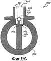
Фиг.9А - упрощенный вид в поперечном сечении электронной системы диагностики разрыва, выполненной с возможностью обнаружения утончения или разрыва части утонченной стенки вихревого расходомера согласно варианту осуществления настоящего изобретения.9A is a simplified cross-sectional view of an electronic fracture diagnostic system configured to detect thinning or tearing of a portion of a refined wall of a vortex flowmeter according to an embodiment of the present invention.
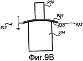
Фиг.9В - расширенное изображение поперечного сечения части утонченной стенки вихревого расходомера по фиг.9А.FIG. 9B is an enlarged cross-sectional view of a portion of the refined wall of the vortex flowmeter of FIG. 9A.
Детальное описаниеDetailed description
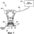
На фиг.1 показана упрощенная диаграмма передатчика промышленного процесса с функцией обнаружения разрыва, согласно варианту осуществления настоящего изобретения. Система 100 содержит передатчик 102, коммуникативно связанный с центром 104 управления посредством канала 106 связи, который может быть проводным или беспроводным. Канал 106 связи связывает электронные схемы, находящиеся внутри корпуса передатчика 102, для контроля и управления, осуществляемого системами в центре 104 управления.1 is a simplified diagram of an industrial process transmitter with a burst detection function according to an embodiment of the present invention.
Дополнительно часть 108 основания передатчика 102 связана со стенкой 110 резервуара производственного процесса с помощью привариваемой опоры 112, которая приварена к стенке 110 резервуара в месте 114 сварного соединения. Передатчик 102 связан резьбовым соединением с привариваемой опорой 112, так что изолирующая диафрагма 116 непосредственно открыта действию технологического флюида в резервуаре через отверстие в стенке 110 резервуара.Additionally, the
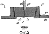
На фиг.2 представлен увеличенный вид поперечного сечения части 108 основания передатчика 102 на фиг.1. Часть 108 основания смонтирована на стенке 110 резервуара посредством привариваемой опоры 112, которая прикреплена к стенке 110 резервуара в месте 114 сварного соединения. Изолирующая диафрагма 116 непосредственно открыта действию технологического флюида в резервуаре через отверстие 118 в стенке 110 резервуара, с одной стороны, и материалу 120 заполнителя-флюида в заполненной флюидом полости 122, с другой стороны. В типовом случае изменения в давлении технологического флюида по отношению к изолирующей диафрагме 116 переносятся через заполнитель-флюид 120 в полости 122 к дистанционному датчику давления (не показан), который связан с изолирующей диафрагмой 116 через заполненный флюидом капилляр 124.Figure 2 presents an enlarged cross-sectional view of
Изолирующая диафрагма 116 представляет собой многослойную емкостную структуру (детально показана на фиг.3). В общем случае многослойная изолирующая диафрагма 116 является достаточно тонкой и гибкой для отклонения в ответ на давление технологического флюида. Многослойная диафрагма 116 связана с электронными схемами, находящимися в корпусе передатчика и адаптированными для обеспечения электронной индикации разрыва, согласно варианту осуществления настоящего изобретения.The
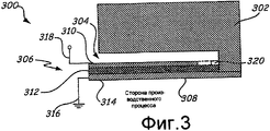
На фиг.3 представлен увеличенный вид поперечного сечения структуры 300 изолирующей диафрагмы, согласно варианту осуществления настоящего изобретения. Следует иметь в виду, что структура 300 изолирующей диафрагмы на фиг.3 показана не в масштабе, а в сильно увеличенном виде в целях пояснения.3 is an enlarged cross-sectional view of an
Структура 300 изолирующей диафрагмы включает в себя передатчик 302 с заполненной флюидом полостью 304 и структуру 306 изолирующей диафрагмы. Структура 306 изолирующей диафрагмы является многослойной структурой, содержащей первый проводящий слой 308 и второй проводящий слой 310, разделенные диэлектрическим материалом 312, который предпочтительно является твердым диэлектрическим материалом.The
Предпочтительно первый проводящий слой 308 имеет поверхность 314, которая непосредственно открыта действию технологического флюида (смоченная поверхность). В типовом случае первый проводящий слой 308 электрически связан с технологической магистралью, трубопроводом или резервуаром, который, в свою очередь, связан с электрическим заземлением 316. Второй проводящий слой 310 снабжен одним или более выводами 318 для измерения изменения емкости или комплексного импеданса структуры 306 диафрагмы.Preferably, the first
В общем случае емкость является отношением заряда к потенциалу напряжения. В конденсаторе с параллельными пластинами, который является одним типом конденсатора, рассматриваемого в настоящем изобретении, емкость определяется по следующей формуле:In general, capacitance is the ratio of charge to voltage potential. In a parallel plate capacitor, which is one type of capacitor considered in the present invention, the capacitance is determined by the following formula:
![]()
![]()
где ε0 - диэлектрическая проницаемость (диэлектрическая постоянная), А представляет площадь пластины и d представляет расстояние между двумя пластинами. Если, как в предпочтительном варианте осуществления настоящего изобретения, диэлектрик образован твердым материалом, то расстояние (d) и диэлектрическая постоянная (ε0) остаются, по существу, постоянными. Однако если площадь (А) пластин изменяется (например, вследствие коррозии или износа), то емкость изменяется. Следовательно, если непроводящий материал, протекающий по трубопроводу, вызывает коррозию первой проводящей пластины 308, то площадь (А) первой проводящей пластины 308 изменяется, вызывая тем самым измеримое изменение в емкости изолирующей диафрагмы 306. Изменение в емкости изолирующей диафрагмы 306 может обеспечить индикацию того, что изолирующая диафрагма 306 требует обслуживания или замены.where ε 0 is the dielectric constant (dielectric constant), A represents the area of the plate and d represents the distance between the two plates. If, as in a preferred embodiment of the present invention, the dielectric is formed by solid material, then the distance (d) and the dielectric constant (ε 0 ) remain essentially constant. However, if the area (A) of the plates changes (for example, due to corrosion or wear), then the capacity changes. Therefore, if the non-conductive material flowing through the pipeline corrodes the first
Если технологический флюид в трубопроводе является непроводящим или находится в неконденсированном газовом состоянии (или если технологический трубопровод является пустым, как в случае, когда система отключена), обнаружение разрыва или утончения первого проводящего слоя 308 может быть обеспечено (как описано выше) путем контроля емкости второго проводящего слоя 310 относительно первого проводящего слоя 308 (или относительно электрического заземления). В принципе система 300 согласно настоящему изобретению обеспечена средством диагностики (показанным на фиг.5), которое адаптировано для приложения напряжения или сигнала к одному или более слоев емкостной диафрагмы 306 и для измерения изменения. Например, в одном варианте осуществления напряжение прикладывается к емкостной диафрагме 306, и постоянная времени оценивается для определения емкости. Если напряжение является периодическим таким, как в случае сигнала ступенчатого напряжения, то изменение в емкости обнаруживается по изменению постоянной времени выходного сигнала. В этом варианте осуществления система 300 адаптирована для обнаружения утончения первого проводящего слоя 308 вследствие износа или коррозии, на основе измеренной емкости диафрагмы 306.If the process fluid in the pipeline is non-conductive or is in a non-condensed gas state (or if the process fluid is empty, as in the case when the system is turned off), the detection of a break or thinning of the first
Однако во многих случаях технологический флюид является проводящим, и коррозию первого проводящего слоя 308 невозможно обнаружить путем прямого измерения емкости. Более конкретно технологический флюид производственного процесса может заполнять любые пустоты или разрывы в первом проводящем слое 308, тем самым поддерживая видимым образом надлежащую площадь поверхности, так что емкость изолирующей диафрагмы 306 не изменяется заметными образом. Тем не менее коррозия может быть обнаружена из измеренного изменения комплексного импеданса на втором проводящем слое 310. Например, уравнение для оценивания состояния емкости может соответствовать следующему уравнению:However, in many cases, the process fluid is conductive, and corrosion of the first
![]()
![]()
где Z представляет отношение величины напряжения к току, умноженное на экспоненту, которое включает в себя как действительную, так и мнимую части. При условии изменения площади первой проводящей пластины 308 импеданс на конденсаторе с параллельными пластинами (структуре изолирующей диафрагмы 306) может изменяться во времени, даже если технологический флюид является проводящим. Измерительная схема (такая как системы 514 анализа сигнала на фиг.5) может быть связана с первой проводящей пластиной 308 и второй проводящей пластиной 310 для измерения электрического параметра емкостной диафрагмы 306 такого, как комплексный импеданс, реактивное сопротивление или другой электрический параметр. Путем приложения ко второй проводящей пластине изменяющегося во времени сигнала (или сигнала, содержащего диапазон частот) изменение в одном или более электрических параметрах может использоваться для вывода состояния первого проводящего слоя.where Z represents the ratio of voltage to current multiplied by the exponential, which includes both the real and imaginary parts. Provided that the area of the first
В одном варианте осуществления диэлектрический материал 312 содержит пористый материал, так что если технологический флюид вызывает коррозию первого проводящего слоя 308, то технологический флюид проходит через диэлектрический материал 312, закорачивая второй проводящий слой 310 на электрическое заземление. В случае пористого диэлектрика дефект первого проводящего слоя 308 может быть обнаружен по резкому изменению в одном или более электрических параметрах диафрагмы 306. В другом варианте осуществления диэлектрический материал 312 может быть выбран так, чтобы вызванная коррозия позволяла притоку технологического флюида контактировать со вторым проводящим слоем 310 и закорачивать второй проводящий слой 310 на электрическое заземление. Если диэлектрический материал 312 выбран как пористый или корродируемый, то второй проводящий слой 310 может быть сконструирован так, чтобы продолжаться, по существу, на всей протяженности диэлектрического слоя 312 (как показано пунктиром). Дополнительно непроводящее уплотнение 320 (показано пунктиром) может быть размещено между вторым проводящим слоем 310 и передатчиком 302 для того, чтобы предотвращать утечку технологического флюида через второй проводящий слой 310 и для электрической изоляции второго проводящего слоя 310 от стенки передатчика 302.In one embodiment, the
В некоторых случаях технологический флюид может быть летучим, и из обычных соображений безопасности емкостная диафрагма 306 может быть адаптирована для предотвращения возникновения искр или электрического разряда в просачивающийся технологический флюид. Например, устройство ограничения напряжения может быть связано с конденсатором для ограничения потенциала напряжения на конденсаторе, чтобы предотвратить воспламенение летучего технологического флюида за счет искр или разряда электрического потенциала.In some cases, the process fluid may be volatile, and for normal safety reasons, the capacitive diaphragm 306 may be adapted to prevent sparks or electrical discharge from leaking into the process fluid. For example, a voltage limiting device may be coupled to a capacitor to limit the voltage potential across the capacitor in order to prevent ignition of the volatile process fluid due to sparks or the discharge of an electric potential.
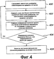
На фиг.4 представлена упрощенная блок-схема процесса принятия решения об утончении или разрыве диафрагмы на основе измеренного электрического параметра. Емкостная диафрагма сканируется изменяющимся во времени сигналом (блок 400). Один или более электрических параметров емкостной диафрагмы измеряются, когда прикладывается изменяющийся во времени сигнал (блок 402). Измеренные электрические параметры сравниваются с сохраненными опорными значениями (блок 404). Если измеренное значение изменяется относительно опорного значения на величину, превышающую предварительно определенный предел (блок 406), то на основе отклонения может быть сделан вывод о разрыве или утончении диафрагмы (блок 408). Если измеренное значение не изменяется относительно опорного значения на величину, превышающую предварительно заданный предел (блок 406), то этапы 400 и последовательность повторяются.Figure 4 presents a simplified flowchart of the decision-making process on thinning or rupture of the diaphragm based on the measured electrical parameter. The capacitive diaphragm is scanned by a time-varying signal (block 400). One or more electrical parameters of the capacitive diaphragm is measured when a time-varying signal is applied (block 402). The measured electrical parameters are compared with the stored reference values (block 404). If the measured value changes relative to the reference value by an amount exceeding the predefined limit (block 406), then based on the deviation, a conclusion can be made about the rupture or thinning of the diaphragm (block 408). If the measured value does not change relative to the reference value by an amount exceeding the predefined limit (block 406), then steps 400 and the sequence are repeated.
В принципе измеряемый электрический параметр может представлять собой емкость или может быть любым числом комплексных электрических параметров (таких как импеданс, реактивное сопротивление, полная проводимость и т.п.). Если установлено утончение или разрыв на основе отклонения от сохраненного опорного значения, то может генерироваться сигнал тревоги, указывающий на выведенное рабочее состояние емкостной диафрагмы, который посылается в центр управления. Следует иметь в виду, что рабочее состояние может находиться в пределах от недействующего или неисправного состояния до полностью действующего состояния. Кроме того, понятно, что величина или степень отклонения может указывать на степень коррозии, износа или повреждения емкостной диафрагмы. Альтернативным образом степень отклонения может указывать на тип коррозии, износа или повреждения (такой как питтинг (точечная коррозия), трещинообразование, равномерный износ, коррозия и т.д.), в зависимости от того, какой из электрических параметров изменяется относительно опорного значения. Треснувшая или полностью разорванная диафрагма может быть обнаружена как разомкнутая цепь или бесконечный импеданс, в то время как отклонения от опорного значения могут указывать на ухудшившееся состояние изолирующей диафрагмы.In principle, the measured electrical parameter can be a capacitance or can be any number of complex electrical parameters (such as impedance, reactance, impedance, etc.). If a thinning or rupture is established based on a deviation from the stored reference value, an alarm may be generated indicating the displayed operating state of the capacitive diaphragm, which is sent to the control center. It should be borne in mind that the operating state can range from an inactive or malfunctioning state to a fully operational state. In addition, it is understood that the magnitude or degree of deviation may indicate the degree of corrosion, wear, or damage to the capacitive diaphragm. Alternatively, the degree of deviation may indicate the type of corrosion, wear or damage (such as pitting (pitting), cracking, uniform wear, corrosion, etc.), depending on which of the electrical parameters changes relative to the reference value. A cracked or completely broken diaphragm can be detected as an open circuit or infinite impedance, while deviations from the reference value may indicate a deteriorated condition of the insulating diaphragm.
В одном варианте осуществления свипирующий сигнал инициируется центром управления. В альтернативном варианте осуществления анализ свипирующего сигнала запускается схемами диагностики и выполняется периодически. Хотя способ по фиг.4 использует изменяющийся во времени сигнал, в некоторых случаях также может использоваться приложенное напряжение постоянного тока. Кроме того, экспертные системы, такие как системы с нечеткой логикой, системы искусственного интеллекта, нейронные сети и т.п., могут использоваться для анализа электрических параметров изолирующей диафрагмы для определения рабочего состояния диафрагмы.In one embodiment, the sweep signal is initiated by a control center. In an alternative embodiment, the sweep signal analysis is triggered by diagnostic circuits and is performed periodically. Although the method of FIG. 4 uses a time-varying signal, in some cases, the applied DC voltage may also be used. In addition, expert systems, such as fuzzy logic systems, artificial intelligence systems, neural networks, etc., can be used to analyze the electrical parameters of an insulating diaphragm to determine the working state of the diaphragm.
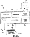
На фиг.5 представлена упрощенная блок-схема системы 500 диагностики согласно варианту ее осуществления в настоящее время. Система 500 диагностики содержит структуру 502 изолирующей диафрагмы, коммуникативно связанную со средством 504 диагностики (которое может быть реализовано в схемах), которое в типовом случае помещено в корпус. Структура диафрагмы включает в себя первый проводящий слой 506 и второй проводящий слой 508, разделенные диэлектрическим материалом 510. Первый проводящий слой 506 открыт действию технологического флюида внутри магистрали или трубопровода производственного процесса. В одном варианте осуществления первый проводящий слой 506 электрически заземлен путем соединения с проводящей стенкой трубопровода. Второй проводящий слой 508 изолирован от технологического флюида и электрически изолирован от первого проводящего слоя 506.5 is a simplified block diagram of a
Средство 504 диагностики включает в себя генератор 512 сигнала, системы 514 анализа комплексного сигнала, микропроцессор 516, приемопередатчик 518, генератор 519 сигнала тревоги и, факультативно, экспертные системы 540, такие как системы искусственного интеллекта, системы с нечеткой логикой, нейронные сети и т.п. Генератор 512 сигнала выполнен в виде схемы, предназначенной для передачи электрического сигнала, такого как изменяющийся во времени сигнал или периодический сигнал. Генератор 512 сигнала передает электрический сигнал по второму проводящему слою 508, для которого могут проводиться измерения и анализ системами 514 анализа комплексного сигнала для обнаружения изменения в одном или более комплексных параметрах системы. Экспертные системы 540 могут использоваться для анализа одного или более электрических параметров и для вывода рабочего состояния изолирующей диафрагмы на основе изменений одного или более электрических параметров относительно сохраненного опорного измерения. Понятно, что системы 514 анализа комплексного сигнала могут содержать один процессор, схемы, предназначенные для обработки измеренных сигналов, емкостной сенсор или любой другой элемент, адаптированный для получения диагностического измеренного значения на основе измеренной емкости.
В одном варианте осуществления настоящего изобретения контролируемый технологический флюид является непроводящим, и системы 514 анализа комплексного сигнала содержат сенсор, адаптированный для измерения емкости изолирующей диафрагмы 502 относительно электрического заземления. В условиях, где технологический флюид является электропроводным, генератор 512 сигналов предпочтительно выполнен с возможностью свипирования второго проводящего слоя 508 электрическими сигналами, имеющими диапазон частот. Системы 514 анализа комплексного сигнала адаптированы для определения комплексного импеданса изолирующей диафрагмы 502 в диапазоне частот свипирования.In one embodiment of the present invention, the monitored process fluid is non-conductive and the complex
Микропроцессор 516 может использоваться для дальнейшей обработки измеренного комплексного импеданса и/или для сравнения измеренного комплексного импеданса с сохраненными значениями, чтобы определить условия тревожной сигнализации. Условие тревожной сигнализации может быть выведено из обнаруженного отклонения, которое изменяется относительно опорного измерения более чем на предварительно заданную величину. Микропроцессор 516 предпочтительно адаптирован для сравнения измеренного изменения импеданса относительно предварительно заданного предела и генерации сигнала тревоги для передачи приемопередатчиком 518 в центр 520 управления по линии связи 522, если измеренное изменение превышает предел. Альтернативно отдельный генератор 519 сигнала тревоги (или схемы генерации сигнала тревоги) может быть использован для генерации сигнала тревоги для передачи приемопередатчиком 518. В одном варианте осуществления, если технологический флюид является непроводящим, системы 514 анализа комплексного сигнала могут просто измерять емкость изолирующего конденсатора 502, и изменение емкости, которое превышает предварительно заданный предел, может вызвать генерацию процессором 516 сигнала тревоги.
Понятно, что элементы системы 500 диагностики могут использоваться совместно с другими компонентами электронных схем 504 передатчика. Например, приемопередатчик 518 также может использоваться сенсорным элементом или системами 514 анализа комплексного сигнала непосредственно, например, для передачи исходных (необработанных) данных в центр управления. Аналогичным образом центр 520 управления может посылать сигнал управления через приемопередатчик 518 для инициирования выполнения нового измерения сенсорным элементом (таким как системы 514 анализа комплексного сигнала). Различные компоненты, такие как генератор 512 сигнала, системы 514 анализа комплексного сигнала и генератор 519 сигнала тревоги, могут быть реализованы полностью или частично в микропроцессоре 516.It is understood that elements of the
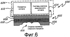
На фиг.6 представлена упрощенная блок-схема системы 600 диагностики согласно варианту осуществления настоящего изобретения. Система 600 диагностики содержит изолирующую емкостную диафрагму 602, связанную со средством 604 диагностики. Диафрагма 602 включает в себя первый проводящий слой 606 и второй проводящий слой 608, разделенные диэлектрическим материалом 610. Генератор 612 сигнала и системы 614 анализа комплексного сигнала электрически связаны со вторым проводящим слоем 608.6 is a simplified block diagram of a
В этом варианте осуществления технологические флюиды в резервуаре привели к коррозии первого проводящего слоя 606 с образованием язв или отверстий 616 в первом проводящем слое 606, частично открывающих диэлектрик 610 действию технологического флюида. Диэлектрик 610 предпочтительно образован твердым материалом, так что повреждение первого проводящего слоя 606 не пропускает диэлектрическую жидкость в технологический флюид. Дополнительно твердый диэлектрик 610 служит в качестве слоя защиты от утечки флюида, заполняющего капилляр, в технологический флюид (например, в дистанционной системе герметизации). Кроме того, твердый диэлектрик 610 служит в качестве слоя защиты от утечки технологического флюида в корпус с электронными схемами (например, если электронные схемы находятся рядом с производственным процессом).In this embodiment, the process fluids in the reservoir corroded the first
Генератор 612 сигналов связан со вторым проводящим слоем 608 и предназначен для передачи электрического сигнала в конкретном диапазоне частот во второй проводящий слой 508. Система 614 анализа комплексного сигнала связана со вторым проводящим слоем 608 и предназначена для обнаружения изменений в свипирующем сигнале на основе изменения в первом проводящем слое 606.A
В одном варианте осуществления, если технологический флюид является непроводящим, то коррозия первого проводящего слоя 606 может быть обнаружена по изменению емкости (или электрического потенциала) между первым и вторым проводящими слоями 606, 608. Однако если, что является более частым, технологический флюид является электропроводным, то генератор 612 сигналов может сканировать второй проводящий слой 608 в диапазоне частот (или изменяющимся во времени сигналом), и системы 614 анализа комплексного сигнала могут быть использованы для обнаружения коррозии на основе изменений в комплексном импедансе. В любом случае, если измеренное изменение превышает предварительно заданный предел, может генерироваться сигнал тревоги для передачи в центр управления.In one embodiment, if the process fluid is non-conductive, then corrosion of the first
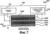
На фиг.7 представлена упрощенная блок-схема системы 700 диагностики согласно варианту осуществления настоящего изобретения. Система 700 диагностики содержит многослойную изолирующую структуру 702 диафрагмы, связанную с передатчиком 704. Изолирующая структура 702 диафрагмы образована из трех слоев 706, 708А и 708В проводящего материала, разделенных друг от друга слоями 710А, 710В диэлектрического материала. Генератор 712 сигналов связан со вторым и третьим слоями 708А и 708В проводящего материала соответственно, в то время как первый слой 706 проводящего материала связан с трубопроводом производственного процесса и поэтому заземлен. Система 714 анализа комплексного сигнала связана со вторым и третьим слоями 708А и 708В проводящего материала соответственно, чтобы контролировать изменения в комплексном импедансе или емкости между каждым из первого и второго проводящих слоев 706 и 708 соответственно и второго и третьего проводящих слоев 708А и 708В соответственно. Дифференциальное изменение в емкости или комплексном импедансе может указывать на разрыв первого проводящего слоя 706.7 is a simplified block diagram of a
В одном варианте осуществления технологический флюид является непроводящим или находится в газообразном состоянии, и коррозия первого проводящего слоя 706 обнаруживается на основе изменения в емкости диафрагмы 702, измеряемой непосредственно. Альтернативно, если технологический флюид является проводящим, то вывод о коррозии первого проводящего слоя 706 может быть сделан исходя из изменения комплексного импеданса структуры 702 диафрагмы. Более конкретно генератор 712 сигнала может сканировать изолированные проводящие слои 708А и 708В в диапазоне частот, и системы 714 анализа комплексного сигнала адаптируются для обнаружения изменений в комплексном импедансе диафрагмы 702. Утончение, износ или коррозия первого проводящего слоя 706 могут обнаруживаться по изменению комплексного импеданса.In one embodiment, the process fluid is non-conductive or in a gaseous state, and corrosion of the first
В целом настоящее изобретение обеспечивает ряд преимуществ по сравнению с уровнем техники. Во-первых, путем замены тонкой пленочной изолирующей диафрагмы многослойной диафрагмой, адаптированной для обеспечения емкостной индикации (или электронной индикации) утончения или разрыва, передатчик может быть адаптирован для диагностики самого себя и для обеспечения сигнала тревоги, указывающего на необходимость обслуживания изолирующей диафрагмы, прежде чем произойдет разрыв диафрагмы и загрязнение процесса. Во-вторых, диэлектрический материал может быть твердым непроводящим материалом, таким как керамика, который поддерживает изоляцию между заполняющим флюидом (таким как тот, который используется в изолирующей диафрагме) и флюидом производственного процесса даже после того, как смоченная поверхность изолирующего элемента разрывается. В-третьих, различные реализации диагностики изолирующего элемента могут обеспечить дополнительные детали о статусе изолирующего элемента. В частности, система диагностики с двумя пластинами может обеспечить исходную индикацию разрыва или утончения, в то время как система диагностики с тремя или более пластинами может обеспечить более сложную и содержательную индикацию степени повреждения изолирующего элемента на основе, частично, дифференциальной емкости. Дополнительно настоящее изобретение применимо к любому производственному оборудованию, которое имеет тонкую область, восприимчивую к коррозии или повреждению под воздействием технологического флюида. Таким образом, настоящее изобретение обеспечивает изолирующий элемент, адаптированный для генерации электрического сигнала, указывающего на потенциальное повреждение изолирующего элемента, прежде чем такое повреждение станет слишком заметным.In General, the present invention provides several advantages compared with the prior art. First, by replacing a thin film insulating diaphragm with a multilayer diaphragm adapted to provide a capacitive indication (or electronic indication) of thinning or rupture, the transmitter can be adapted to diagnose itself and to provide an alarm indicating the need to maintain the insulating diaphragm before diaphragm rupture and process fouling will occur. Secondly, the dielectric material may be a solid, non-conductive material, such as ceramic, which maintains insulation between the filling fluid (such as that used in the insulating diaphragm) and the fluid of the manufacturing process even after the wetted surface of the insulating element is torn. Thirdly, various diagnostic implementations of an insulating element can provide additional details about the status of the insulating element. In particular, a diagnostic system with two plates can provide an initial indication of a gap or thinning, while a diagnostic system with three or more plates can provide a more complex and meaningful indication of the degree of damage to an insulating element based, in part, on differential capacitance. Additionally, the present invention is applicable to any manufacturing equipment that has a thin area susceptible to corrosion or damage due to the process fluid. Thus, the present invention provides an insulating element adapted to generate an electrical signal indicative of potential damage to the insulating element before such damage becomes too noticeable.
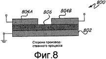
На фиг.8 представлена упрощенная блок-схема альтернативной структуры 800 изолирующей диафрагмы соответственно варианту осуществления настоящего изобретения. Структура 800 изолирующей диафрагмы содержит первый проводящий слой 802 и второй проводящий слой 804, разделенный на две электрически отдельные пластины 804А и 804В и отделенный от первого проводящего слоя 802 диэлектриком 806. В этом варианте осуществления изменение в площади первого проводящего слоя 802, например, из-за коррозии, может быть обнаружено на основе дифференциальной емкости, измеренной на пластинах 804А и 804В. В альтернативном варианте осуществления может использоваться измерение комплексного импеданса, как описано выше. В этом случае комплексный импеданс измеряется на обеих пластинах 804А и 804В отдельно, на основе генерируемых сигналов. В одном варианте осуществления разность фаз, измеренная на двух пластинах 804А и 804В, основанная на одном и том же сигнале, может быть указателем коррозии.FIG. 8 is a simplified block diagram of an alternative isolating diaphragm structure 800 according to an embodiment of the present invention. The insulating diaphragm structure 800 comprises a first
В этом варианте осуществления емкость может измеряться на или между этими двумя полупластинами 804А и 804В. Измеряемая емкость может изменяться при изменении площади, обусловленной коррозией первого проводящего слоя 802. Однако если технологический флюид является проводящим, то прямое измерение емкости может не выявить какой-либо информации о состоянии первого проводящего слоя 802. В этом случае, если технологический флюид является проводящим, первая полупластина 804А может сканироваться в диапазоне частот. Вторая полупластина 804В может контролироваться на изменение в фазе или амплитуде измеряемого сигнала в конкретном диапазоне частот. Изменение в измеренном выходном сигнале может указывать на изменение в площади первого проводящего слоя 802. Процесс, связанный с коррозией, утончением или износом, может быть выявлен в зависимости от конкретного изменения в измеренном выходном сигнале.In this embodiment, the capacitance can be measured on or between the two half-
На фиг.9А показан упрощенный вид в поперечном сечении системы вихревого расходомера, включающей в себя емкостную изолирующую диафрагму согласно настоящему изобретению в тонкостенной части стенки трубопровода. Трубопровод 902 разделен на два пути потока с помощью обтекаемой планки 904. Обтекаемая планка 904 продолжается от тонкостенной части 912 стенки трубопровода и связана со стойкой 906, так что движение обтекания или колебательное движение обтекаемой планки 904, обусловленное флюидными вихрями в трубопроводе 902, может обнаруживаться на основе движения или вибрации стойки 906. Сенсор 908 (показан пунктиром) в типовом случае связан со стойкой 906 для измерения скорости флюида в трубопроводе 902 на основе движения стойки 906. В общем случае сенсор 908 и другие электронные схемы процесса расположены вне трубопровода 902 и в корпусе 910 передатчика.FIG. 9A shows a simplified cross-sectional view of a vortex flowmeter system including a capacitive insulating diaphragm according to the present invention in a thin-walled portion of a pipe wall.
В общем случае обтекаемая планка 904 связана со стойкой 906 через тонкостенную часть 912. Тонкостенная часть 912 предпочтительно достаточно тонка для передачи движения обтекаемой планки через стенку трубопровода на стойку 906, где сенсор 908 адаптирован для измерения скорости потока флюида в трубопроводе 902 на основе движения стойки 906. Проблема, возникающая, в частности, в средах с высоким давлением, связана с поддержанием достаточной толщины в тонкостенной части 912, чтобы предотвратить разрыв стенки при высоком давлении и при этом обеспечить достаточную гибкость для движения. Выводы 914 могут быть предусмотрены для соединения со схемой диагностики.In general, the
Многослойная изолирующая диафрагма согласно настоящему изобретению может быть использована в таких применениях для обеспечения изоляции от технологического флюида, а также диагностики разрыва.The multilayer insulating diaphragm according to the present invention can be used in such applications to provide isolation from the process fluid, as well as fracture diagnostics.
На фиг.9В представлен увеличенный вид в поперечном сечении элемента 900 расходомера с тонкостенной частью 912, образованной из любой из структур изолирующих емкостных диафрагм, описанных выше со ссылками на фиг.3 и 5-7. В этом варианте осуществления структура 912 диафрагмы представляет собой емкостную структуру 926. Емкостная структура 926 образована из первого емкостного слоя 920, связанного со стенкой трубопровода и обращенного к технологическому флюиду непосредственно рядом с обтекаемой планкой 904. Второй проводящий слой 924 отделен от первого проводящего слоя 920 диэлектрическим материалом 922. Второй проводящий слой 924 изолирован от технологического флюида вне трубопровода и рядом со стойкой 906. Выводы 914 могут быть обеспечены от второго проводящего слоя, чтобы обнаружить изменение в комплексном импедансе и/или в емкости емкостной структуры 926.FIG. 9B is an enlarged cross-sectional view of a
В этом варианте осуществления диэлектрик 922 предпочтительно является твердым непроводящим материалом. Слои емкостной структуры 926 обеспечивают дополнительную прочность, обеспечивая средство для обнаружения коррозии или износа первого проводящего слоя 920. В частности, путем контроля комплексного импеданса и/или емкости емкостной структуры 926, коррозия или износ тонкостенной части 912 могут быть обнаружены прежде, чем произойдет разрыв или повреждение, тем самым предотвращая внеплановые отключения и/или открытие чувствительных электронных схем в передатчике воздействию технологического флюида из трубопровода.In this embodiment, the dielectric 922 is preferably a solid non-conductive material. The layers of the capacitive structure 926 provide additional strength by providing a means for detecting corrosion or wear of the first
В целом, настоящее изобретение использует установленную закономерность, что емкость пропорциональна площади поверхности пластин, в конфигурации с параллельными пластинами. Если слой пленки, ближайший к производственному процессу, начинает утончаться или разрываться, то эффективная площадь диафрагмы изменяется на величину разрыва или в степени утончения. Это изменение в эффективной площади диафрагмы обуславливает изменение в измеряемой емкости параллельных пластин.In General, the present invention uses the established pattern that the capacity is proportional to the surface area of the plates, in a configuration with parallel plates. If the film layer closest to the production process begins to thin or rupture, the effective aperture area changes by the amount of gap or the degree of thinning. This change in the effective diaphragm area causes a change in the measured capacitance of the parallel plates.
Это предполагает, что технологический флюид, для которого проводятся измерения, является непроводящим. В таком случае, если емкость диафрагмы непрерывно контролируется, то коррозия, износ, эрозия или питтинг приведут к измеряемому изменению в емкости. Это измеряемое изменение обеспечивает своевременную индикацию потенциальных проблем, имеющих место для изолирующей диафрагмы или тонкостенной части. Схемы, связанные с емкостным изолирующим элементом, могут затем незамедлительно оповестить центр управления о том, что возник разрыв или что изолирующая диафрагма или тонкостенная часть могут потребовать обслуживания.This suggests that the process fluid for which measurements are being made is non-conductive. In this case, if the capacity of the diaphragm is continuously monitored, then corrosion, wear, erosion or pitting will lead to a measurable change in capacity. This measurable change provides a timely indication of potential problems that occur for an insulating diaphragm or thin-walled portion. Circuits associated with a capacitive insulating element can then immediately notify the control center that a gap has occurred or that the insulating diaphragm or thin-walled part may require maintenance.
Во многих производственных процессах технологический флюид, контактирующий с изолирующей диафрагмой, сам является проводящим. В таком случае непосредственное измерение емкости между слоями пленки может не позволить выявить измеряемое изменение в емкости, когда обращенная к технологическому флюиду пленка подвергается коррозии. Более конкретно проводящий технологический флюид может протечь в зону коррозии пленки, тем самым заполняя или заменяя корродированные зоны пленки проводящим флюидом. В таком случае измеряемая емкость может остаться неизменной. Однако может быть использована схема, адаптированная для измерения комплексных электрических параметров, таких как комплексный импеданс, реактивное сопротивление и т.п., для измерения свипирующей частоты. Изменения в одном или более комплексных электрических параметрах могут отражать наличие полости, утончения или иных изменений в пленке изолирующей диафрагмы, открытой влиянию производственного процесса при различных рабочих условиях. Одна схема генерации может быть использована для сканирования одного из слоев пленки, и схема измерения может быть использована для измерения свипирующей частоты, что может демонстрировать изменения в случае, когда один или более пленочных слоев повреждены технологическим флюидом.In many manufacturing processes, the process fluid in contact with the insulating diaphragm is itself conductive. In this case, a direct measurement of the capacitance between the layers of the film may not allow detecting the measured change in the capacitance when the film facing the process fluid is corroded. More specifically, the conductive process fluid may leak into the corrosion zone of the film, thereby filling or replacing the corroded zones of the film with the conductive fluid. In this case, the measured capacitance may remain unchanged. However, a circuit adapted to measure complex electrical parameters, such as complex impedance, reactance, etc., to measure the sweep frequency can be used. Changes in one or more complex electrical parameters may reflect the presence of a cavity, thinning, or other changes in the film of the insulating diaphragm open to the influence of the manufacturing process under various operating conditions. One generation circuit can be used to scan one of the layers of the film, and a measurement circuit can be used to measure the sweep frequency, which can demonstrate changes when one or more of the film layers is damaged by the process fluid.
В принципе, системы и способы, соответствующие настоящему изобретению, контролируют электрические параметры емкостной изолирующей диафрагмы. Один или более электрических параметров могут изменяться, если изолирующая диафрагма утончается, подвергается коррозии или иным образом повреждается в процессе работы. Системы анализа сигналов могут сравнивать измеренные параметры с сохраненными опорными параметрами. Альтернативно системы анализа сигналов включают в себя экспертные системы, адаптированные для вывода рабочего состояния диафрагмы на основе изменения в электрических параметрах в зависимости от времени. Электрические параметры могут включать в себя емкость. Альтернативно электрические параметры могут включать в себя комплексные электрические параметры, такие как комплексный импеданс, реактивное сопротивление, полная проводимость и т.п. Наконец, технологический флюид может находиться в жидком состоянии или в газообразном состоянии.In principle, the systems and methods of the present invention control the electrical parameters of a capacitive insulating diaphragm. One or more electrical parameters may change if the insulating diaphragm becomes thinner, corrodes, or is otherwise damaged during operation. Signal analysis systems can compare measured parameters with stored reference parameters. Alternatively, signal analysis systems include expert systems adapted to output the operating state of the diaphragm based on a change in electrical parameters as a function of time. Electrical parameters may include capacitance. Alternatively, the electrical parameters may include complex electrical parameters such as complex impedance, reactance, impedance, and the like. Finally, the process fluid may be in a liquid state or in a gaseous state.
Хотя настоящее изобретение описано со ссылками на предпочтительные варианты осуществления, специалистам в данной области техники должно быть очевидно, что возможны изменения по форме и в деталях без отклонения от сущности и объема настоящего изобретения.Although the present invention has been described with reference to preferred embodiments, it will be apparent to those skilled in the art that changes in form and detail are possible without departing from the spirit and scope of the present invention.
Claims (35)
диафрагму, выполненную с возможностью связывания устройства производственного процесса с технологическим флюидом, причем диафрагма имеет множество слоев, первый слой из множества слоев подвергается воздействию технологического флюида производственного процесса; и
схему диагностики, связанную с диафрагмой, для контроля электрического параметра диафрагмы и определения в ответ на это рабочего состояния диафрагмы на основе изменения в контролируемом электрическом параметре, причем электрический параметр представляет собой функцию от приложенного к диафрагме изменяющегося во времени сигнала.1. The diagnostic system of multilayer diaphragms for use in the device of the production process, containing
a diaphragm configured to couple the production process device to the process fluid, the diaphragm having a plurality of layers, the first layer of the plurality of layers being exposed to the process fluid of the manufacturing process; and
a diagnostic circuit associated with the diaphragm for monitoring the electric parameter of the diaphragm and determining, in response to this, the working state of the diaphragm based on a change in the controlled electrical parameter, the electric parameter being a function of the time-varying signal applied to the diaphragm.
средство генерирования сигнала тревоги, предназначенное для генерации сигнала тревоги, указывающего на установленное рабочее состояние диафрагмы, если упомянутое изменение превышает предварительно заданный предел.2. The diagnostic system of multilayer diaphragms according to claim 1, additionally containing
alarm generating means for generating an alarm indicative of a set operational state of the diaphragm if said change exceeds a predetermined limit.
генератор сигнала, предназначенный для сканирования изолирующей диафрагмы изменяющимся во времени сигналом, причем электрический параметр включает в себя комплексный электрический параметр диафрагмы.4. The diagnostic system of multilayer diaphragms according to claim 1, additionally containing
a signal generator for scanning an insulating diaphragm with a time-varying signal, the electric parameter including a complex electric parameter of the diaphragm.
системы анализа комплексного сигнала, предназначенные для контроля диафрагмы для обнаружения изменений в электрическом параметре относительно сохраненного опорного сигнала на основе изменяющегося во времени сигнала.5. The diagnostic system of multilayer diaphragms according to claim 4, further comprising
complex signal analysis systems designed to control the diaphragm to detect changes in the electrical parameter relative to the stored reference signal based on a time-varying signal.
по меньшей мере, два электропроводных слоя и
по меньшей мере, один диэлектрический слой, разделяющий, по меньшей мере, два электропроводных слоя.8. The system for diagnosing multilayer diaphragms according to claim 1, in which many layers contain
at least two electrically conductive layers and
at least one dielectric layer separating at least two electrically conductive layers.
обеспечивают изолирующую диафрагму, содержащую множество слоев, причем первый слой из множества слоев непосредственно подвергается воздействию технологического флюида производственного процесса;
прикладывают электрический сигнал к изолирующей диафрагме; и
определяют в ответ на это рабочее состояние диафрагмы на основе измеренного изменения в электрическом параметре изолирующей диафрагмы относительно приложенного электрического сигнала, причем электрический параметр представляет собой функцию от приложенного к диафрагме изменяющегося во времени сигнала.12. The method of determining the operating state of the multilayer insulating diaphragm, which consists in the fact that
provide an insulating diaphragm containing many layers, and the first layer of the many layers is directly exposed to the process fluid of the production process;
applying an electrical signal to the insulating diaphragm; and
determining in response to this operating state of the diaphragm based on the measured change in the electrical parameter of the insulating diaphragm relative to the applied electrical signal, the electrical parameter being a function of the time-varying signal applied to the diaphragm.
по меньшей мере, два электропроводных слоя и
по меньшей мере, один диэлектрический слой, разделяющий, по меньшей мере, два электропроводных слоя.22. The method of claim 12, wherein the plurality of layers comprises
at least two electrically conductive layers and
at least one dielectric layer separating at least two electrically conductive layers.
емкостной элемент, выполненный с возможностью связывания устройства производственного процесса с технологическим флюидом, причем емкостной элемент имеет множество слоев, первый слой из множества слоев подвергается воздействию технологического флюида производственного процесса; и
схему диагностики, связанную с емкостным элементом, для контроля электрического параметра емкостного элемента и определения в ответ на это рабочего состояния емкостного элемента на основе изменения в контролируемом электрическом параметре, причем электрический параметр представляет собой функцию от приложенного к диафрагме изменяющегося во времени сигнала.23. The diagnostic system of multilayer diaphragms for use in the device of the production process, containing
a capacitive element configured to couple the production process device to the process fluid, the capacitive element having a plurality of layers, the first layer of the plurality of layers being exposed to the process fluid of the manufacturing process; and
a diagnostic circuit associated with the capacitive element for monitoring the electric parameter of the capacitive element and determining in response to this the operational state of the capacitive element based on a change in the controlled electric parameter, the electric parameter being a function of the time-varying signal applied to the diaphragm.
генератор сигнала, предназначенный для сканирования емкостного элемента электрическим сигналом, имеющим изменяющийся во времени компонент; и
системы анализа комплексного сигнала, адаптированные для контроля емкостного элемента и для вывода рабочего состояния емкостного элемента на основе изменения в одном или более электрических параметрах емкостного элемента относительно сохраненного опорного измерения.29. The diagnostic system of multilayer diaphragms according to item 23, in which the diagnostic circuit further comprises
a signal generator for scanning a capacitive element with an electric signal having a time-varying component; and
complex signal analysis systems adapted to monitor a capacitive element and to derive the operational state of a capacitive element based on a change in one or more electrical parameters of the capacitive element relative to the stored reference measurement.
по меньшей мере, два электропроводных слоя и
по меньшей мере, один диэлектрический слой, разделяющий, по меньшей мере, два электропроводных слоя.33. The diagnostic system of multilayer diaphragms according to item 23, in which many layers contain
at least two electrically conductive layers and
at least one dielectric layer separating at least two electrically conductive layers.
Applications Claiming Priority (2)
| Application Number | Priority Date | Filing Date | Title |
|---|---|---|---|
| US11/031,953 US7295131B2 (en) | 2005-01-07 | 2005-01-07 | Diagnostic system for detecting rupture or thinning of diaphragms |
| US11/031,953 | 2005-01-07 |
Publications (2)
| Publication Number | Publication Date |
|---|---|
| RU2007130123A RU2007130123A (en) | 2009-02-20 |
| RU2397484C2 true RU2397484C2 (en) | 2010-08-20 |
Family
ID=36123390
Family Applications (1)
| Application Number | Title | Priority Date | Filing Date |
|---|---|---|---|
| RU2007130123/28A RU2397484C2 (en) | 2005-01-07 | 2005-12-15 | Diagnostic system for determining diaphragm rapture or thinning |
Country Status (6)
| Country | Link |
|---|---|
| US (1) | US7295131B2 (en) |
| EP (1) | EP1834174B1 (en) |
| JP (1) | JP5398990B2 (en) |
| CN (1) | CN101099083B (en) |
| RU (1) | RU2397484C2 (en) |
| WO (1) | WO2006073752A1 (en) |
Families Citing this family (19)
| Publication number | Priority date | Publication date | Assignee | Title |
|---|---|---|---|---|
| US8633825B2 (en) * | 2006-08-08 | 2014-01-21 | Wessels Company | Expansion tank with a predictive sensor |
| US20080035647A1 (en) * | 2006-08-08 | 2008-02-14 | James Fuller | Expansion tank with a predictive sensor |
| DE102011002900A1 (en) * | 2011-01-20 | 2012-07-26 | Siemens Aktiengesellschaft | Pressure Transmitter |
| US8466696B2 (en) * | 2011-03-30 | 2013-06-18 | GM Global Technology Operations LLC | System and method for detecting a likelihood of corrosion |
| US9244033B2 (en) * | 2013-01-24 | 2016-01-26 | GM Global Technology Operations LLC | Method for online detection of liner buckling in a storage system for pressurized gas |
| EP3117202B1 (en) | 2014-03-14 | 2019-01-02 | Rosemount Inc. | Corrosion rate measurement |
| US10830689B2 (en) | 2014-09-30 | 2020-11-10 | Rosemount Inc. | Corrosion rate measurement using sacrificial probe |
| DE102014118616A1 (en) * | 2014-12-15 | 2016-06-16 | Endress + Hauser Gmbh + Co. Kg | pressure transducers |
| US10190968B2 (en) | 2015-06-26 | 2019-01-29 | Rosemount Inc. | Corrosion rate measurement with multivariable sensor |
| JP6842328B2 (en) * | 2017-03-23 | 2021-03-17 | エドワーズ株式会社 | Vacuum pump, main sensor, and thread groove stator |
| CN107607595B (en) * | 2017-09-21 | 2020-05-12 | 京东方科技集团股份有限公司 | Optical filter detection device and method |
| CN108375629A (en) * | 2018-01-30 | 2018-08-07 | 昆明理工大学 | A kind of pulsed eddy-current nondestructive test system based on flexible PCB technology |
| WO2019222598A1 (en) | 2018-05-17 | 2019-11-21 | Rosemount Inc. | Measuring element and measuring device comprising the same |
| DE102018118645B3 (en) | 2018-08-01 | 2019-11-07 | Ifm Electronic Gmbh | Method for monitoring the function of a pressure measuring cell of a capacitive pressure sensor |
| US11061064B2 (en) * | 2019-05-15 | 2021-07-13 | Nanya Technology Corporation | Semiconductor device and method for detecting cracks |
| US11243134B2 (en) | 2019-09-30 | 2022-02-08 | Rosemount Inc. | Pressure sensing device isolation cavity seal monitoring |
| CN111678957A (en) * | 2020-06-03 | 2020-09-18 | 福州瑞芯微电子股份有限公司 | Crack detection device and method and electronic equipment |
| CN112947136A (en) * | 2021-01-16 | 2021-06-11 | 河南检亿科技有限公司 | Intelligent monitoring device for aging degree of steel lining storage tank, monitoring process and method |
| CN114659698B (en) * | 2022-03-06 | 2024-04-09 | 淮安市格洋浩瑞电子科技有限公司 | Impact-resistant high-stability flat membrane type pressure sensor |
Family Cites Families (40)
| Publication number | Priority date | Publication date | Assignee | Title |
|---|---|---|---|---|
| BE628704A (en) * | 1962-02-22 | |||
| US3946726A (en) * | 1974-08-07 | 1976-03-30 | Puriton-Bennett Corporation | Pulmonary diagnostic instrument including breath transducer |
| US3968693A (en) * | 1975-05-21 | 1976-07-13 | Fischer & Porter Co. | Open-loop differential-pressure transmitter |
| US4653508A (en) * | 1976-06-21 | 1987-03-31 | Cosman Eric R | Pressure-balanced telemetric pressure sensing system and method therefore |
| US4660568A (en) * | 1976-06-21 | 1987-04-28 | Cosman Eric R | Telemetric differential pressure sensing system and method therefore |
| US4281666A (en) * | 1976-06-21 | 1981-08-04 | Cosman Eric R | Single diaphragm pressure-balanced telemetric pressure sensing system |
| US4206761A (en) * | 1976-06-21 | 1980-06-10 | Cosman Eric R | Pressure-balanced telemetric pressure sensing method |
| JPS58109779A (en) * | 1981-12-23 | 1983-06-30 | Matsushita Electric Ind Co Ltd | Gas pressure regulator |
| BE893660A (en) | 1982-06-25 | 1982-10-18 | Centre Rech Metallurgique | Continuous monitoring of converter tuyere wear - using capacitor positioned in tuyere |
| US4571537A (en) * | 1982-07-02 | 1986-02-18 | Nartron Corporation | Condition monitoring means |
| US4934902A (en) * | 1984-09-27 | 1990-06-19 | Myron Mantell | Failure sensing device for a diaphragm pump |
| JPS61237053A (en) * | 1985-04-15 | 1986-10-22 | Nippon Telegr & Teleph Corp <Ntt> | Corrosion life diagnosing apparatus for zinc galvanized steel |
| US4777826A (en) * | 1985-06-20 | 1988-10-18 | Rosemount Inc. | Twin film strain gauge system |
| US4971523A (en) * | 1988-09-13 | 1990-11-20 | Nordson Corporation | Dual diaphragm apparatus with diaphragm assembly and rupture detection methods |
| DE3932443C1 (en) * | 1989-09-28 | 1990-12-20 | Endress U. Hauser Gmbh U. Co, 7864 Maulburg, De | |
| US5208162A (en) * | 1990-05-08 | 1993-05-04 | Purafil, Inc. | Method and apparatus for monitoring corrosion |
| JPH04194718A (en) * | 1990-11-28 | 1992-07-14 | Yokogawa Electric Corp | Differential pressure measuring device |
| JPH05288706A (en) * | 1992-04-06 | 1993-11-02 | Sumitomo Metal Ind Ltd | Monitoring system of defect of metal member |
| JP2822816B2 (en) * | 1992-10-29 | 1998-11-11 | 株式会社日立製作所 | Semiconductor sensor, transmitter and process status display device |
| CA2169824A1 (en) * | 1993-09-24 | 1995-03-30 | Roger L. Frick | Pressure transmitter isolation diaphragm |
| AU4110596A (en) * | 1994-11-30 | 1996-06-19 | Rosemount Inc. | Pressure transmitter with fill fluid loss detection |
| US6484585B1 (en) * | 1995-02-28 | 2002-11-26 | Rosemount Inc. | Pressure sensor for a pressure transmitter |
| US5734098A (en) * | 1996-03-25 | 1998-03-31 | Nalco/Exxon Energy Chemicals, L.P. | Method to monitor and control chemical treatment of petroleum, petrochemical and processes with on-line quartz crystal microbalance sensors |
| JPH10148591A (en) * | 1996-09-19 | 1998-06-02 | Fuji Koki Corp | Pressure detector |
| US6029525A (en) * | 1998-02-04 | 2000-02-29 | Mks Instruments, Inc. | Capacitive based pressure sensor design |
| US6120033A (en) * | 1998-06-17 | 2000-09-19 | Rosemount Inc. | Process diaphragm seal |
| CA2359230A1 (en) * | 1999-01-27 | 2000-08-03 | Richard A. Wenman | Method and device for measuring the acidity or basicity of insulating fluids, particularly mineral and synthetic oils |
| US6295875B1 (en) * | 1999-05-14 | 2001-10-02 | Rosemount Inc. | Process pressure measurement devices with improved error compensation |
| BR0014361A (en) * | 1999-09-28 | 2002-06-11 | Rosemount Inc | Environmentally sealed instrument circuit adapter, and, process transmitter |
| US6508129B1 (en) * | 2000-01-06 | 2003-01-21 | Rosemount Inc. | Pressure sensor capsule with improved isolation |
| US6425290B2 (en) * | 2000-02-11 | 2002-07-30 | Rosemount Inc. | Oil-less differential pressure sensor |
| US6662662B1 (en) * | 2000-05-04 | 2003-12-16 | Rosemount, Inc. | Pressure transmitter with improved isolator system |
| DE10024118A1 (en) * | 2000-05-18 | 2001-11-29 | Freudenberg Carl Fa | Device for monitoring the integrity of a membrane |
| US6518880B2 (en) * | 2000-06-28 | 2003-02-11 | Denso Corporation | Physical-quantity detection sensor |
| US6782754B1 (en) * | 2000-07-07 | 2004-08-31 | Rosemount, Inc. | Pressure transmitter for clean environments |
| JP2002156301A (en) * | 2000-11-20 | 2002-05-31 | Yokogawa Electric Corp | Differential pressure/pressure transmitter |
| US6684711B2 (en) * | 2001-08-23 | 2004-02-03 | Rosemount Inc. | Three-phase excitation circuit for compensated capacitor industrial process control transmitters |
| JP2003247943A (en) * | 2002-02-26 | 2003-09-05 | Mitsubishi Heavy Ind Ltd | Nondestructive inspection method for ceramic coating material |
| DE10233561B4 (en) * | 2002-07-24 | 2008-02-21 | Prominent Dosiertechnik Gmbh | Safety diaphragm for a diaphragm pump |
| US6941853B2 (en) * | 2003-12-02 | 2005-09-13 | Wanner Engineering, Inc. | Pump diaphragm rupture detection |
-
2005
- 2005-01-07 US US11/031,953 patent/US7295131B2/en active Active
- 2005-12-15 RU RU2007130123/28A patent/RU2397484C2/en not_active IP Right Cessation
- 2005-12-15 EP EP05854450.3A patent/EP1834174B1/en active Active
- 2005-12-15 JP JP2007550383A patent/JP5398990B2/en not_active Expired - Fee Related
- 2005-12-15 CN CN200580046260.1A patent/CN101099083B/en active Active
- 2005-12-15 WO PCT/US2005/045734 patent/WO2006073752A1/en active Application Filing
Also Published As
| Publication number | Publication date |
|---|---|
| EP1834174A1 (en) | 2007-09-19 |
| JP5398990B2 (en) | 2014-01-29 |
| JP2008527347A (en) | 2008-07-24 |
| US7295131B2 (en) | 2007-11-13 |
| EP1834174B1 (en) | 2017-06-21 |
| US20060152380A1 (en) | 2006-07-13 |
| WO2006073752A1 (en) | 2006-07-13 |
| CN101099083A (en) | 2008-01-02 |
| CN101099083B (en) | 2010-12-08 |
| RU2007130123A (en) | 2009-02-20 |
Similar Documents
| Publication | Publication Date | Title |
|---|---|---|
| RU2397484C2 (en) | Diagnostic system for determining diaphragm rapture or thinning | |
| US10156480B2 (en) | Thermowell vibration frequency diagnostic | |
| RU2636408C1 (en) | Measurement of corrosion rate | |
| RU2407997C2 (en) | Pressure sensor fault detection | |
| JP5323848B2 (en) | Process control transmitter with vibration sensor | |
| CA2878920C (en) | Thermal diagnostic for single-crystal process fluid pressure sensor | |
| CN102243124A (en) | Resonant frequency based pressure sensor | |
| JP2005181317A (en) | Seal for remote processing with improved stability in specific use | |
| US20160341623A1 (en) | Pressure Transducer and Method for Operating the Pressure Transducer | |
| JP2008527347A5 (en) | ||
| WO1993024819A1 (en) | Detecting degradation of non-conductive inert wall layers in fluid containers | |
| CN1280639C (en) | Diagnostics for piezoelectric sensor | |
| JP2017501406A (en) | Leak monitoring system for objects surrounding a space and their joints and associated method | |
| US20160290560A1 (en) | Monitoring of a condensate drain | |
| JP2004530910A (en) | Prediction device for corrosion monitoring | |
| CN211904570U (en) | Industrial process differential pressure sensing device and pressure sensor isolation device | |
| US11391698B2 (en) | Dome-shape tuning fork transducers for corrosion monitoring | |
| US10883951B2 (en) | Arrangement and method for detecting damage to an inner coating of a container | |
| Feydo et al. | Non-intrusive ultrasonic corrosion-rate measurement in lieu of manual and intrusive methods | |
| WO2019160987A2 (en) | Dipstick and electronic fluid level sensor | |
| JPH09210946A (en) | Water-cooled bearing |
Legal Events
| Date | Code | Title | Description |
|---|---|---|---|
| MM4A | The patent is invalid due to non-payment of fees |
Effective date: 20191216 |