RU2397076C2 - System and method of power accumulation in hybrid propulsion system - Google Patents
System and method of power accumulation in hybrid propulsion system Download PDFInfo
- Publication number
- RU2397076C2 RU2397076C2 RU2007103196/11A RU2007103196A RU2397076C2 RU 2397076 C2 RU2397076 C2 RU 2397076C2 RU 2007103196/11 A RU2007103196/11 A RU 2007103196/11A RU 2007103196 A RU2007103196 A RU 2007103196A RU 2397076 C2 RU2397076 C2 RU 2397076C2
- Authority
- RU
- Russia
- Prior art keywords
- power
- electric motor
- link
- energy storage
- electric
- Prior art date
Links
Images


Classifications
-
- B—PERFORMING OPERATIONS; TRANSPORTING
- B60—VEHICLES IN GENERAL
- B60L—PROPULSION OF ELECTRICALLY-PROPELLED VEHICLES; SUPPLYING ELECTRIC POWER FOR AUXILIARY EQUIPMENT OF ELECTRICALLY-PROPELLED VEHICLES; ELECTRODYNAMIC BRAKE SYSTEMS FOR VEHICLES IN GENERAL; MAGNETIC SUSPENSION OR LEVITATION FOR VEHICLES; MONITORING OPERATING VARIABLES OF ELECTRICALLY-PROPELLED VEHICLES; ELECTRIC SAFETY DEVICES FOR ELECTRICALLY-PROPELLED VEHICLES
- B60L50/00—Electric propulsion with power supplied within the vehicle
- B60L50/50—Electric propulsion with power supplied within the vehicle using propulsion power supplied by batteries or fuel cells
- B60L50/60—Electric propulsion with power supplied within the vehicle using propulsion power supplied by batteries or fuel cells using power supplied by batteries
-
- B—PERFORMING OPERATIONS; TRANSPORTING
- B60—VEHICLES IN GENERAL
- B60L—PROPULSION OF ELECTRICALLY-PROPELLED VEHICLES; SUPPLYING ELECTRIC POWER FOR AUXILIARY EQUIPMENT OF ELECTRICALLY-PROPELLED VEHICLES; ELECTRODYNAMIC BRAKE SYSTEMS FOR VEHICLES IN GENERAL; MAGNETIC SUSPENSION OR LEVITATION FOR VEHICLES; MONITORING OPERATING VARIABLES OF ELECTRICALLY-PROPELLED VEHICLES; ELECTRIC SAFETY DEVICES FOR ELECTRICALLY-PROPELLED VEHICLES
- B60L2200/00—Type of vehicles
- B60L2200/26—Rail vehicles
-
- B—PERFORMING OPERATIONS; TRANSPORTING
- B60—VEHICLES IN GENERAL
- B60L—PROPULSION OF ELECTRICALLY-PROPELLED VEHICLES; SUPPLYING ELECTRIC POWER FOR AUXILIARY EQUIPMENT OF ELECTRICALLY-PROPELLED VEHICLES; ELECTRODYNAMIC BRAKE SYSTEMS FOR VEHICLES IN GENERAL; MAGNETIC SUSPENSION OR LEVITATION FOR VEHICLES; MONITORING OPERATING VARIABLES OF ELECTRICALLY-PROPELLED VEHICLES; ELECTRIC SAFETY DEVICES FOR ELECTRICALLY-PROPELLED VEHICLES
- B60L2210/00—Converter types
- B60L2210/20—AC to AC converters
-
- Y—GENERAL TAGGING OF NEW TECHNOLOGICAL DEVELOPMENTS; GENERAL TAGGING OF CROSS-SECTIONAL TECHNOLOGIES SPANNING OVER SEVERAL SECTIONS OF THE IPC; TECHNICAL SUBJECTS COVERED BY FORMER USPC CROSS-REFERENCE ART COLLECTIONS [XRACs] AND DIGESTS
- Y02—TECHNOLOGIES OR APPLICATIONS FOR MITIGATION OR ADAPTATION AGAINST CLIMATE CHANGE
- Y02T—CLIMATE CHANGE MITIGATION TECHNOLOGIES RELATED TO TRANSPORTATION
- Y02T10/00—Road transport of goods or passengers
- Y02T10/60—Other road transportation technologies with climate change mitigation effect
- Y02T10/70—Energy storage systems for electromobility, e.g. batteries
-
- Y—GENERAL TAGGING OF NEW TECHNOLOGICAL DEVELOPMENTS; GENERAL TAGGING OF CROSS-SECTIONAL TECHNOLOGIES SPANNING OVER SEVERAL SECTIONS OF THE IPC; TECHNICAL SUBJECTS COVERED BY FORMER USPC CROSS-REFERENCE ART COLLECTIONS [XRACs] AND DIGESTS
- Y02—TECHNOLOGIES OR APPLICATIONS FOR MITIGATION OR ADAPTATION AGAINST CLIMATE CHANGE
- Y02T—CLIMATE CHANGE MITIGATION TECHNOLOGIES RELATED TO TRANSPORTATION
- Y02T10/00—Road transport of goods or passengers
- Y02T10/60—Other road transportation technologies with climate change mitigation effect
- Y02T10/72—Electric energy management in electromobility
Abstract
Description
Уровень техникиState of the art
Изобретение относится, в целом, к гибридным движительным системам и, в частности, к системе и способу для распределенного накопления энергии в гибридных движительных приложениях большой мощности.The invention relates, in General, to hybrid propulsion systems and, in particular, to a system and method for distributed energy storage in high-power hybrid propulsion applications.
Некоторые транспортные средства используют тяговые электродвигатели для приведения в движение транспортного средства. Как правило, тяговые электродвигатели присоединены к звену, такому как шина, которое предоставляет двигателям мощность. Один или более бортовых генераторов переменного тока (ПерТ) могут быть использованы для предоставления мощности звену. В определенных рабочих состояниях, таких, когда транспортное средство тормозит или поддерживает скорость при движении вниз по уклону, производимая электродвигателями обратная ЭДС больше, чем напряжение, предоставляемое генераторами ПерТ с приводом от двигателя. В таких состояниях тяговые электродвигатели перестают действовать как двигатели и переходят в режим генераторов ПерТ. Этот процесс, известный как динамическое торможение, является формой электрического торможения, которая используется для сокращения износа механических компонентов тормозной системы транспортного средства. В случае, когда транспортным средством является локомотив, динамическое торможение сокращает износ локомотива, а также всех рельсовых тележек в составе поезда. Как правило, для рассеивания электроэнергии, производимой электродвигателями в течение динамического торможения, в форме теплоты используется резистор.Some vehicles use traction motors to propel the vehicle. Typically, traction motors are connected to a link, such as a tire, that provides motors with power. One or more on-board alternators (PER) can be used to provide power to the link. In certain operating conditions, such as when the vehicle slows down or maintains speed when driving downhill, the reverse emf produced by the electric motors is greater than the voltage provided by the PerT generators driven by the engine. In such states, traction motors cease to act as engines and switch to the PerT generator mode. This process, known as dynamic braking, is a form of electrical braking that is used to reduce wear on the mechanical components of a vehicle’s brake system. In the case where the vehicle is a locomotive, dynamic braking reduces the wear of the locomotive, as well as all rail cars in the train. Typically, a resistor is used in the form of heat to dissipate the electricity produced by electric motors during dynamic braking.
Гибридные движительные системы были разработаны с целью рекуперации части энергии, которая бесполезно расходуется в форме теплоты во время динамического торможения. Рекуперация этой бесполезно расходуемой энергии известна как регенеративное торможение. Транспортные средства, имеющие мощные гибридные движительные системы, такие как автобусы, большегрузные грузовики, транспортные средства для горной промышленности и локомотивы, могут привести к необходимости массивных модулей накопления энергии, которые, как правило, содержат батареи, ультра-конденсаторы, маховик или комбинации из одной или более этих технологий. Одним из примеров является гибридная движительная система для локомотива с мощной тягой. В подобных применениях движущая сила обычно предоставляется первичным двигателем, таким как дизельный двигатель, который непосредственно соединен с генератором ПерТ и связанным мощным выпрямителем, который преобразовывает выходную мощность генератора из переменного тока (ПерТ) в постоянный ток (ПосТ). Выход выпрямителя соединен с главным звеном ПосТ, которое может снабжать мощностью несколько двигателей. Как правило, модуль накопления энергии электрически соединен с главным звеном ПосТ через электронный преобразователь ПосТ/ПосТ, который контролируется системой энергоуправления и связанными управляющими блоками системы транспортного средства. Преобразователь ПосТ/ПосТ предоставляет двунаправленный интерфейс ПосТ/ПосТ для модуля накопления энергии так, что модуль накопления энергии действует, чтобы снабжать мощностью тяговые двигатели и чтобы получать мощность от тяговых двигателей в течение регенеративного торможения. Мощность от тяговых двигателей используется для частичной зарядки модуля накопления энергии. Таким образом, энергия, которая обычно рассеивается в реостате в форме теплоты в течение динамического торможения, рекуперируется и используется для частичной зарядки модулей накопления энергии. Позже модуль накопления энергии может быть разряжен для снабжения тяговых двигателей мощностью. При наличии соответствующих системных средств управления гибридная движительная система может быть использована для предоставления ускорения транспортному средству с уменьшенной выходной мощностью от дизельного двигателя, таким образом сокращая количество топлива, необходимое для данной задачи, по сравнению с обычным негибридным локомотивом.Hybrid propulsion systems have been developed to recover some of the energy that is wasted in the form of heat during dynamic braking. The recovery of this useless energy is known as regenerative braking. Vehicles with powerful hybrid propulsion systems such as buses, heavy trucks, mining vehicles and locomotives can necessitate massive energy storage modules that typically contain batteries, ultra-capacitors, a flywheel, or combinations of one or more of these technologies. One example is a hybrid propulsion system for a locomotive with powerful traction. In such applications, the driving force is usually provided by a prime mover, such as a diesel engine, which is directly connected to the PerT generator and a connected powerful rectifier that converts the generator output from AC (PerT) to direct current (POS). The rectifier output is connected to the main POST link, which can supply several motors with power. As a rule, the energy storage module is electrically connected to the main POST link through the PosT / PosT electronic converter, which is controlled by the energy management system and the associated control units of the vehicle system. The PosT / PosT converter provides a bi-directional PosT / PosT interface for the energy storage module so that the energy storage module acts to provide power to the traction motors and to receive power from the traction motors during regenerative braking. The power from the traction motors is used to partially charge the energy storage module. Thus, energy, which is usually dissipated in the rheostat in the form of heat during dynamic braking, is recovered and used to partially charge the energy storage modules. Later, the energy storage module may be discharged to provide power to the traction motors. With the appropriate system controls, a hybrid propulsion system can be used to provide acceleration to a vehicle with reduced output from a diesel engine, thereby reducing the amount of fuel needed for a given task compared to a conventional non-hybrid locomotive.
Несмотря на это, существует ряд проблем, связанных с существующими гибридными движительными системами. Для мощных транспортных средств, как правило, требуется двунаправленный интерфейс ПосТ/ПосТ для накопителя энергии, вследствие меньшей номинальной мощности модулей накопления энергии в сравнении с номинальной мощностью первичного двигателя. Однако электронные компоненты, необходимые для двунаправленного преобразователя Пост/Пост, значительно увеличивают стоимость оборудования силовой электроники. Например, в течение нормального режима работы мощного транспортного средства, напряжение главного звена ПосТ, как правило, варьирует в пределах приблизительно от 250 В до 1500 В. Для снижения стоимости преобразователя ПосТ/ПосТ выходное напряжение модуля накопления энергии, как правило, выбирается либо больше, либо меньше значения напряжения звена ПосТ в течение гибридного режима работы. Тем не менее, когда требуется, чтобы система накопления энергии в гибридной движительной системе работала и на напряжении, которое выше напряжения звена ПосТ, и на напряжении, которое ниже напряжения звена ПосТ, в преобразователе ПосТ/ПосТ, как правило, используется Н-образная конфигурация моста. Однако Н-образная конфигурация моста требует, по меньшей мере, в два раза больше силовых электронных переключателей, что приводит к значительному увеличению стоимости преобразователя ПосТ/ПосТ. Также, преобразователь ПосТ/ПосТ большой номинальной мощности представляет потенциальную проблему надежности. Более того, вследствие требований большей мощности, модули накопления энергии обычных гибридных движительных систем требуют работы в параллельном режиме многочисленных меньших модулей накопления энергии. Однако разделение мощности в параллельно соединенных модулях накопления энергии может вызвать проблему в течение работы по широкому диапазону крайних значений температуры окружающей среды. Если разделение мощности не контролируется соответствующим образом, срок службы модулей накопления энергии может сократиться.Despite this, there are a number of problems associated with existing hybrid propulsion systems. Powerful vehicles typically require a bi-directional PosT / PosT interface for energy storage, due to the lower rated power of the energy storage modules compared to the rated power of the prime mover. However, the electronic components required for a bidirectional Post / Post converter significantly increase the cost of power electronics equipment. For example, during the normal mode of operation of a powerful vehicle, the voltage of the main POST link usually varies from approximately 250 V to 1500 V. To reduce the cost of the POST / POST converter, the output voltage of the energy storage module is usually selected either more or or less than the voltage of the PosT link during the hybrid operating mode. Nevertheless, when it is required that the energy storage system in the hybrid propulsion system operate at a voltage that is higher than the voltage of the PosT link, and at a voltage that is lower than the voltage of the PosT link, the H-configuration is usually used in the PosT / PosT converter the bridge. However, the H-shaped bridge configuration requires at least two times more power electronic switches, which leads to a significant increase in the cost of the PosT / PosT converter. Also, a PosT / PosT converter with high rated power presents a potential reliability problem. Moreover, due to higher power requirements, the energy storage modules of conventional hybrid propulsion systems require the parallel operation of many smaller energy storage modules. However, power sharing in parallel connected energy storage modules can cause a problem during operation over a wide range of extreme ambient temperature values. If power sharing is not adequately controlled, the life of the energy storage modules may be reduced.
В дополнение, в обычных мощных гибридных транспортных средствах различные электрические устройства (такие как электроосвещение, вентиляторы, воздушный компрессор) снабжаются мощностью от двигателя. Это означает, что для снабжения электрических устройств мощностью двигатель должен работать даже тогда, когда транспортное средство тормозит или движется вниз по уклону. Это приводит к значительно уменьшенной экономии топлива.In addition, in conventional high-power hybrid vehicles, various electrical devices (such as electric lights, fans, an air compressor) are powered by the engine. This means that in order to supply electrical devices with power, the engine must operate even when the vehicle is braking or moving downhill. This results in significantly reduced fuel economy.
Соответственно, желательны методы для снижения стоимости и/или улучшения энергоэффективности гибридных движительных систем. В особенности, желательны методы для увеличения количества регенеративной тормозной мощности, которая производится гибридными движительными системами мощных транспортных средств и которая может быть рекуперирована.Accordingly, methods for reducing cost and / or improving energy efficiency of hybrid propulsion systems are desirable. In particular, methods are desirable for increasing the amount of regenerative braking power that is produced by the hybrid propulsion systems of powerful vehicles and which can be recovered.
Раскрытие изобретенияDisclosure of invention
В одной особенности настоящего метода предоставлена движительная система, которая имеет один или более гибридных движительных тяговых приводов. Гибридные движительные тяговые приводы имеют в своем составе электродвигатель, который действует, чтобы производить механическую мощность для движения и чтобы генерировать электрическую мощность в течение динамического торможения электродвигателя. Гибридный движительный тяговый привод содержит модуль накопления энергии, который действует, чтобы снабжать электродвигатель мощностью для выработки механической мощности для движения и чтобы получать электрическую мощность от электродвигателя в течение динамического торможения электродвигателя. Предоставлен переключатель, который действует, чтобы выборочно присоединять модуль накопления энергии к электродвигателю на основании рабочего параметра движительной системы.In one aspect of the present method, a propulsion system is provided that has one or more hybrid propulsion traction drives. Hybrid propulsion traction drives incorporate an electric motor that acts to produce mechanical power for movement and to generate electrical power during dynamic braking of the electric motor. The hybrid propulsion traction drive comprises an energy storage module that operates to provide electric power to the motor to generate mechanical power for movement and to receive electric power from the electric motor during dynamic braking of the electric motor. A switch is provided that acts to selectively attach an energy storage module to an electric motor based on an operating parameter of the propulsion system.
ЧертежиBlueprints
Эти и другие функциональные особенности, отличительные признаки и преимущества настоящего изобретения будет легче понять после изучения следующего подробного описания, со ссылкой на сопутствующие чертежи, на которых одинаковые символы представляют одинаковые части во всех чертежах, где:These and other functional features, features and advantages of the present invention will be easier to understand after studying the following detailed description, with reference to the accompanying drawings, in which the same symbols represent the same parts in all the drawings, where:
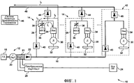
на фиг.1 показана схема гибридной движительной системы, иллюстрирующая поток мощности в режиме работы системы на малой мощности, в соответствии с иллюстративным вариантом осуществления настоящего метода;figure 1 shows a diagram of a hybrid propulsion system illustrating the power flow in the mode of operation of the system at low power, in accordance with an illustrative embodiment of the present method;
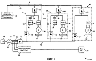
на фиг.2 показана схема гибридной движительной системы с фиг.1, иллюстрирующая поток мощности в режиме работы системы на большой мощности;figure 2 shows a diagram of the hybrid propulsion system of figure 1, illustrating the power flow in the mode of operation of the system at high power;
на фиг.3 показана схема альтернативного варианта осуществления гибридной движительной системы, в соответствии с иллюстративным вариантом осуществления настоящего метода;figure 3 shows a diagram of an alternative embodiment of a hybrid propulsion system, in accordance with an illustrative embodiment of the present method;
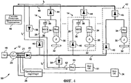
на фиг.4 показана схема альтернативного варианта осуществления системы с фиг.3, иллюстрирующая снабжение вспомогательного оборудования мощностью в течение режима торможения на большой мощности;figure 4 shows a diagram of an alternative embodiment of the system of figure 3, illustrating the supply of auxiliary equipment with power during braking at high power;
на фиг.5 показана схема второго альтернативного варианта осуществления гибридной движительной системы, иллюстрирующая зарядку модуля накопления энергии посредством тягового двигателя в течение режима торможения на большой мощности;5 is a diagram of a second alternative embodiment of a hybrid propulsion system illustrating charging a power storage module by a traction motor during a high power braking mode;
на фиг.6 показана схема третьего альтернативного варианта осуществления гибридной движительной системы.6 shows a diagram of a third alternative embodiment of a hybrid propulsion system.
Осуществление изобретенияThe implementation of the invention
Настоящий метод предоставляет распределенную систему накопления энергии и способ для использования в гибридных движительных системах. Этот метод будет особенно полезен в мощных транспортных средствах, таких как междугородные автобусы, грузовики, локомотивы, внедорожные транспортные средства и т.п.The present method provides a distributed energy storage system and method for use in hybrid propulsion systems. This method will be especially useful in powerful vehicles, such as intercity buses, trucks, locomotives, off-road vehicles, etc.
На фиг.1 и 2 проиллюстрирована гибридная движительная система 10 в соответствии с особенностями настоящего метода. Система 10 содержит бортовую систему 12 генерации мощности, которая действует для снабжения мощностью, по меньшей мере, одного гибридного движительного тягового привода 14. Гибридные движительные тяговые приводы 14 электрически соединены с бортовой системой 12 генерации мощности посредством главного звена 16 постоянного тока (ПосТ). Термин «звено ПосТ» используется здесь для указания положительных и отрицательных шин ПосТ, части которых работают на различных напряжениях вследствие наличия различных компонентов в системе 10. Иллюстрированная бортовая система 12 генерации мощности использует тепловой двигатель 18, такой как бензиновый двигатель, дизельный двигатель, газотурбина и т.п. Тепловой двигатель 18 соединен с генератором 20 переменного тока (ПерТ) с возможностью передачи приводного усилия. Генератор 20 ПерТ преобразует механическую выходную мощность теплового двигателя 18 в трехфазную электрическую мощность ПерТ. Трехфазная выходная мощность ПерТ генератора 20 ПерТ соединена с шиной или звеном 21 ПерТ. Выпрямитель 22 используется для преобразования выходной мощности ПерТ генератора 20 ПерТ в выходную мощность ПосТ. Выход выпрямителя 22 соединен с главным звеном 16 ПосТ. В этом варианте осуществления генератор 20 ПерТ действует, чтобы снабжать мощностью вспомогательное оборудование 24 посредством преобразователя 26 ПерТ/ПерТ. Вспомогательное оборудование 24 может включать бортовую систему электроосвещения, вентиляторы, воздушный компрессор и т.п. Тем не менее, специалист в данной области техники оценит, что вспомогательное оборудование 24 может работать на постоянном токе, предоставляемом главным звеном 16 ПосТ.1 and 2, a
Каждый из иллюстрированных гибридных движительных тяговых приводов 14 имеет локальное звено 28 ПосТ, которое соединяет мощность с тяговым двигателем 30. В иллюстрированном варианте осуществления, тяговые двигатели являются двигателями ПерТ. Однако также могут быть использованы двигатели ПосТ. Предоставлен инвертер 34 для преобразования ПосТ на локальном звене 28 ПосТ в ПерТ. Гибридный движительный тяговый привод 14, кроме того, содержит модуль 36 накопления энергии, соединенный с локальным звеном 28 ПосТ. В различных вариантах осуществления модуль 36 накопления энергии может быть в форме батареи, ультра-конденсатора, маховика или иного типа устройства накопления энергии. В дополнение, между модулем 36 накопления энергии и локальным звеном 28 ПосТ расположен переключатель 38. Переключатель 38 может быть контактом реле или иным типом устройства управления электрическим потоком. В этом варианте осуществления переключатели 38 автоматически замыкаются, когда тепловой двигатель 18 работает на малой мощности, и размыкаются, когда тепловой двигатель 18 работает на большей мощности. Однако, для управления работой переключателей 38 может быть использован другой критерий, такой как напряжение, производимое генератором 20 ПерТ. В еще одном варианте осуществления один или более гибридных движительных тяговых приводов 14 могут содержать множество электродвигателей 30 вместе со связанными инвертерами 34. А в еще одном варианте осуществления один или более гибридных движительных тяговых приводов 14 могут содержать множество модулей 36 накопления энергии.Each of the illustrated hybrid propulsion traction drives 14 has a
Напряжение на локальном звене 28 ПосТ может сильно меняться. Между главным звеном 16 ПосТ и каждым локальным звеном 28 ПосТ расположен блокировочный диод 40 для того, чтобы предотвратить поток тока от каждого локального звена 28 ПосТ к главному звену 16 ПосТ, когда напряжение на локальном звене 28 ПосТ больше напряжения на главном звене 16 ПосТ. В соответствии с настоящим методом, множество гибридных движительных тяговых приводов 14 могут быть параллельно соединены с главным звеном 16 ПосТ.The voltage at the local 28 POS link can vary greatly. A blocking
Система 10 также может содержать один или более обычных тяговых приводов 42, которые не используют гибридный движительный принцип. Количество гибридных движительных тяговых приводов 14 может варьировать от, по меньшей мере, одного до всех тяговых приводов, использованных в движительной системе. Также как и гибридные движительные тяговые приводы 14, обычные тяговые приводы 42 могут быть соединены с главным звеном ПосТ посредством блокировочного диода 43.
В нормальном режиме работы мощность подается в каждый из гибридных движительных тяговых приводов 14 посредством бортовой системы 12 генерации мощности через главное звено 16 ПосТ. Однако, в течение режима работы двигателя 18 на малой мощности, такого как при ускорении транспортного средства из пускового положения, напряжение главного звена 16 ПосТ меньше, чем напряжение модулей 36 накопления энергии. Например, в локомотиве, работающем на малой мощности, напряжение на главном звене 16 ПосТ может быть приблизительно 200 В, тогда как рабочее напряжение модуля 36 накопления энергии может быть примерно 600 В. В таком случае переключатель 38 замыкается, как показано на фиг.1, и модуль 36 накопления энергии соединяется с локальным звеном 28 ПосТ, чтобы предоставить модулю 36 накопления энергии возможность снабжать двигатель 30 мощностью. Электрический ток, обозначенный стрелкой I1, протекает от модуля 36 накопления энергии к двигателю 30.In normal operation, power is supplied to each of the hybrid propulsion traction drives 14 through the on-board
В течение режима торможения на малой мощности электродвигатели 30 работают как генераторы ПерТ. Каждый инвертер 34 преобразует выходную мощность ПерТ двигателя 30 в выходную мощность ПосТ, обозначенную стрелкой I2, которая подается к локальному звену 28 ПосТ для того, чтобы частично зарядить модуль 36 накопления энергии. Когда модуль 36 накопления энергии полностью заряжен или когда мощность, производимая тяговым двигателем 30, превосходит способности модулей 36 накопления энергии принять ее, электрический ток от двигателя 30 направляется через дополнительные блокировочные диоды 44 и 45 к системе 46 резистора динамического торможения посредством звена 48 ПосТ динамического торможения. Система 46 резистора динамического торможения содержит резистор, как правило, имеющий большую номинальную мощность, который используется для рассеивания производимой тяговыми двигателями 30 регенеративной тормозной мощности в форме теплоты.During the low-power braking mode, the
Как показано на фиг.2, при увеличении скорости двигателя 18, выходная мощность генератора 20 ПерТ также увеличивается. В течение такой работы двигателя 18 на большой скорости и большой мощности, напряжение главного звена ПосТ может быть больше, чем напряжение модуля 36 накопления энергии. Например, при работе на большой мощности, напряжение на главном звене 16 ПосТ может быть приблизительно 1400-1500 В, тогда как рабочее напряжение модуля 36 накопления энергии может быть приблизительно 600 В. Поток мощности от главного звена 16 ПосТ к модулю 36 накопления энергии при работе на большой мощности может привести к состоянию перенапряжения в модуле 36 накопления энергии. Соответственно, переключатель 38 размыкается, тем самым отсоединяя модуль 36 накопления энергии от локального звена 28 ПосТ. Как результат, в течение работы на больших мощностях, регенеративная мощность от тяговых двигателей 30 не направляется к модулю 36 накопления энергии. Вместо того, регенеративная мощность направляется к системе 46 резистора динамического торможения через второй блокировочный диод 44 посредством звена 48 динамического торможения. Поток тока от двигателя 30 к системе 46 резистора в целом обозначен стрелкой I3.As shown in figure 2, with increasing speed of the
Система 10 может работать с различными напряжениями на локальных звеньях 28 ПосТ. Когда присутствуют один или более обычных приводов 42, предоставляется либо блокировочный диод 43, либо блокировочный диод 45 для того, чтобы предотвратить бесконтрольную циркуляцию токов между разными модулями 36 накопления энергии через блокировочный диод 44 одного гибридного тягового привода или блокировочный диод 40 другого гибридного тягового привода 14.
Предпочтительно, блокировочный диод 43 имеет номинал, достаточный для того, чтобы проводить максимальную величину тока, которая потребляется системой 42 негибридного тягового привода. В течение работы двигателя 18 на малой мощности может быть возможно замкнуть один или более из переключателей 38 и предоставить мощности возможность протекать от одного или более соответствующих модулей 36 накопления энергии через блокировочные диоды 44 для того, чтобы снабжать мощностью негибридную тяговую систему 42. Однако в течение динамического торможения, мощность динамического торможения, вырабатываемая системой 42 негибридного тягового привода, не сможет быть использована для зарядки какого-либо модуля 36 накопления энергии, так как она будет блокирована блокировочным диодом 43 негибридного звена ПосТ.Preferably, the blocking
Блокировочный диод 45 негибридного звена ПосТ динамического торможения желательно имеет номинал, достаточный для того, чтобы проводить максимальный ток динамического торможения, генерируемый системой 42 негибридного тягового привода. В течение режима динамического торможения транспортного средства будет возможно замкнуть один или более из переключателей 38 и предоставить мощности динамического торможения возможность протекать от негибридной тяговой системы 42 для того, чтобы зарядить один или более из соответствующих модулей 36 накопления энергии через блокировочные диоды 40. Тем не менее, в течение работы двигателя 18 на малой мощности, будет невозможно передать мощность к системе 42 негибридного тягового привода от какого-либо модуля 36 накопления энергии, так как она будет блокирована блокировочным диодом 45 негибридного звена ПосТ динамического торможения.The blocking
Иллюстрированный выше вариант осуществления настоящего метода, таким образом, исключает использование дорогих преобразователей ПосТ/ПосТ и может быть полезно использован во многих применениях, таких как локомотив сортировочного парка, который, как правило, работает на довольно малых скоростях и малых мощностях в пределах сортировочного парка.The embodiment of the present method illustrated above, thus, eliminates the use of expensive PosT / PosT converters and can be useful in many applications, such as a locomotive of the sorting fleet, which, as a rule, operates at rather low speeds and low capacities within the sorting fleet.
На фиг.3 и 4 иллюстрирован и в целом обозначен цифрой 50 альтернативный вариант осуществления гибридной движительной системы, которая действует, чтобы рекуперировать регенеративную мощность в течение торможения транспортного средства на большой мощности. Иллюстрированная система 50 содержит вспомогательное оборудование 51, которое может быть запитано либо от бортовой системы 12 генерации мощности посредством главного звена 16 ПосТ, либо регенеративной тормозной мощностью, снабжаемой двигателем 30 посредством звена 28 ПосТ динамического торможения.3 and 4, an alternative embodiment of a hybrid propulsion system that is operative to recover regenerative power during vehicle braking at high power is illustrated and generally indicated by the numeral 50. The illustrated
В иллюстрированном варианте осуществления вспомогательное оборудование получает мощность от вспомогательного звена 52 ПосТ через инвертер 53. Между главным звеном 16 ПосТ и вспомогательным звеном 52 ПосТ предоставлен блокировочный диод 54. Еще один блокировочный диод 56 предоставлен между звеном 48 ПосТ динамического торможения и вспомогательным звеном 52 ПосТ. В течение нормального режима работы системы 50 напряжение на главном звене 16 ПосТ смещает блокировочный диод 54 в прямом направлении. Ток, обозначенный стрелкой I4, протекает через блокировочный диод 54 к инвертеру 53 и дальше к вспомогательному электрическому оборудованию 51.In the illustrated embodiment, the auxiliary equipment receives power from the POST
Как показано на фиг.4, в течение режима торможения на большой мощности динамическое торможение двигателей 30 в гибридных движительных приводах 14 повышает напряжение на локальных звеньях 28 ПосТ сверх величины напряжения на главном звене 16 ПосТ, что приводит к протеканию тока, обозначенного в целом стрелкой I5, через блокировочный диод 44 в звено 48 динамического торможения. Так как обратная ЭДС, производимая тяговыми двигателями 30 гибридных движительных приводов 14, больше напряжения на главном звене 16 ПосТ, блокировочный диод 56, соединяющий звено 48 динамического торможения с вспомогательным звеном 52 ПосТ, смещается в прямом направлении. Это позволяет мощности протекать к вспомогательному звену 52 ПосТ от тяговых двигателей 30. От вспомогательного звена 52 ПосТ мощность протекает к вспомогательному оборудованию 51. Это также приводит к обратному смещению блокировочного диода 54, который блокирует поток мощности от главного звена 16 ПосТ к вспомогательному оборудованию 24.As shown in FIG. 4, during high-power braking, the dynamic braking of
В альтернативном варианте осуществления один или более из блокировочных диодов 40, 43 и 54 замещены одним или более переключателями, которые могут быть контактом реле или любым другим типом устройства управления электрическим потоком. Эти переключатели могут управляться так, чтобы они не проводили ток, когда желательно, чтобы мощность не протекала от звена 16 ПосТ согласно вышеописанной управляющей логике соответствующего диода 40, 43 и 54. В еще одном варианте осуществления один или более из блокировочных диодов 44, 45 и 56 замещены одним или более переключателями, которые управляются так, чтобы они не проводили ток, когда желательно, чтобы мощность не протекала к звену 48 ПосТ динамического торможения согласно вышеописанной управляющей логике соответствующего диода 44, 45 и 56. Использование переключателя может снизить потери на электропроводность диэлектрика по сравнению с использованием диода на том же месте.In an alternative embodiment, one or more of the blocking
На фиг.5 иллюстрирована гибридная движительная система 58 согласно еще одному альтернативному варианту осуществления настоящего метода. Система 58 дополнительно содержит преобразователь 60 ПосТ/ПосТ, который используется для подачи регенеративной тормозной мощности от двигателя 30 в модуль 36 накопления энергии в течение режима торможения на большой мощности и, как правило, на большой скорости. Производимая тяговыми двигателями 30 обратная ЭДС больше, когда двигатели 30 тормозятся на большей мощности и большей скорости, чем на меньшей мощности и меньшей скорости. При уровнях меньшей мощности и, как правило, меньшей скорости регенеративная тормозная мощность от электродвигателя 30 подается на модули 36 накопления энергии через переключатель 38. Однако в течение режима торможения на большой мощности, как было показано ранее, переключатели 38 разомкнуты. Поэтому регенеративная мощность, генерируемая тяговыми двигателями 30, не подается через переключатели 38 для зарядки модулей 36 накопления энергии. Вместо этого, регенеративная мощность направляется через блокировочный диод 44 к звену 48 ПосТ динамического торможения. От звена 48 ПосТ динамического торможения ток, генерируемый тяговыми двигателями 30, обозначенный в целом стрелкой I6, соединяется с преобразователем 60 ПосТ/ПосТ. Как правило, преобразователь 60 ПосТ/ПосТ используется для понижения напряжения звена 48 ПосТ динамического торможения до уровня напряжения в рабочем диапазоне модулей 36 накопления энергии. Выходная мощность преобразователя 60 ПосТ/ПосТ направляется к модулям 36 накопления энергии через блокировочный диод 62. Часть выходной мощности преобразователя 60 ПосТ/ПосТ может быть направлена для снабжения вспомогательного оборудования 51 посредством диода 64 через вспомогательное звено 52 ПосТ, соединенное с инвертером 53.5 illustrates a
Система 58 полезна, так как преобразователь 60 ПосТ/ПосТ может иметь меньшую номинальную мощность, чем преобразователи ПосТ/ПосТ, используемые в обычных гибридных движительных системах. Кроме того, преобразователь 60 ПосТ/ПосТ не должен быть двунаправленным, то есть электрический ток протекает через преобразователь 60 ПосТ/ПосТ только в одном направлении, а не в двух. Более того, преобразователь 60 ПосТ/ПосТ обходится (то есть ток проходит не через него), когда электродвигатель 30 работает на меньшей мощности и, как правило, меньшей скорости, тем самым, увеличивая эффективность процесса зарядки модулей 36 накопления энергии.
На фиг.6 иллюстрирован альтернативный вариант осуществления движительной системы, которая в целом обозначена ссылочным номером 66. В этом варианте осуществления гибридные движительные тяговые приводы 68 напрямую соединены со звеном 21 ПерТ посредством выпрямителя 70. Также используется выпрямитель 72 для предоставления мощности обычным движительным тяговым приводам 74. Однако выпрямитель 72 меньше выпрямителя 22 с фиг.1, так как для передачи электричества от звена 21 ПерТ к локальному звену 28 ПосТ используется более одного выпрямителя. В дополнение, выпрямитель 72 блокирует циркуляцию тока от одного модуля 36 накопления энергии к другому, без блокировочных диодов 43 и 45.6 illustrates an alternative embodiment of the propulsion system, which is generally designated 66. In this embodiment, the hybrid propulsion traction drives 68 are directly connected to the
Таким образом, настоящий метод предоставляет рекуперацию регенеративной тормозной энергии в широком диапазоне мощности и скорости транспортного средства. В дополнение, используемые аппаратные средства несложны и относительно недороги. Несмотря на то что здесь были иллюстрированы и описаны только определенные функциональные особенности изобретения, специалисты в данной области техники могут осуществить многочисленные возможные модификации и изменения. Таким образом, прилагаемая формула изобретения охватывает все подобные модификации и изменения, которые также относятся к настоящему изобретению.Thus, this method provides regenerative braking energy recovery over a wide range of vehicle power and speed. In addition, the hardware used is simple and relatively inexpensive. Although only certain functional features of the invention have been illustrated and described herein, those skilled in the art can make numerous possible modifications and changes. Thus, the appended claims cover all such modifications and changes that also apply to the present invention.
Claims (31)
Applications Claiming Priority (2)
| Application Number | Priority Date | Filing Date | Title |
|---|---|---|---|
| US10/878,804 | 2004-06-28 | ||
| US10/878,804 US7190133B2 (en) | 2004-06-28 | 2004-06-28 | Energy storage system and method for hybrid propulsion |
Publications (2)
| Publication Number | Publication Date |
|---|---|
| RU2007103196A RU2007103196A (en) | 2008-08-10 |
| RU2397076C2 true RU2397076C2 (en) | 2010-08-20 |
Family
ID=34978617
Family Applications (1)
| Application Number | Title | Priority Date | Filing Date |
|---|---|---|---|
| RU2007103196/11A RU2397076C2 (en) | 2004-06-28 | 2005-06-21 | System and method of power accumulation in hybrid propulsion system |
Country Status (11)
| Country | Link |
|---|---|
| US (1) | US7190133B2 (en) |
| EP (1) | EP1763451B1 (en) |
| CN (1) | CN1976828B (en) |
| AT (1) | ATE534546T1 (en) |
| AU (2) | AU2005267432B2 (en) |
| BR (1) | BRPI0512448A (en) |
| CA (1) | CA2570827C (en) |
| MX (1) | MXPA06015114A (en) |
| RU (1) | RU2397076C2 (en) |
| WO (1) | WO2006012089A2 (en) |
| ZA (1) | ZA200700380B (en) |
Families Citing this family (64)
| Publication number | Priority date | Publication date | Assignee | Title |
|---|---|---|---|---|
| FR2866607A1 (en) * | 2004-02-23 | 2005-08-26 | Herve Benjamin Afriat | Urban transmission line for streetcar, has power supply unit supplying average power, and one supply rail electrically joined with running rail, while other supply rail is electrically distinct from running rails |
| US7940016B2 (en) * | 2004-08-09 | 2011-05-10 | Railpower, Llc | Regenerative braking methods for a hybrid locomotive |
| WO2007010326A1 (en) * | 2005-07-20 | 2007-01-25 | Ecosol Solar Technologies, Inc. | A photovoltaic power output-utilizing device |
| DE102006000788A1 (en) * | 2006-01-04 | 2007-07-12 | Siemens Ag | Method and device for transporting goods by rail |
| US7992662B2 (en) * | 2006-01-18 | 2011-08-09 | General Electric Company | Vehicle and method of assembling same |
| CA2655334C (en) * | 2006-06-13 | 2014-08-05 | Railpower Technologies Corp. | Load-lifting apparatus and method of storing energy for the same |
| US8244419B2 (en) * | 2006-10-24 | 2012-08-14 | Mi-Jack Canada, Inc. | Marine power train system and method of storing energy in a marine vehicle |
| US7812555B2 (en) * | 2007-04-30 | 2010-10-12 | Caterpillar Inc | Electric powertrain system having bidirectional DC generator |
| US8001906B2 (en) * | 2007-05-07 | 2011-08-23 | General Electric Company | Electric drive vehicle retrofit system and associated method |
| US7723932B2 (en) * | 2007-05-07 | 2010-05-25 | General Electric Company | Propulsion system |
| US9073448B2 (en) * | 2007-05-07 | 2015-07-07 | General Electric Company | Method of operating propulsion system |
| US9061680B2 (en) | 2007-07-12 | 2015-06-23 | Odyne Systems, Llc | Hybrid vehicle drive system and method for fuel reduction during idle |
| US8408341B2 (en) | 2007-07-12 | 2013-04-02 | Odyne Systems, Llc | Hybrid vehicle drive system and method and idle reduction system and method |
| US20120207620A1 (en) | 2007-07-12 | 2012-08-16 | Odyne Systems, LLC. | Hybrid vehicle drive system and method and idle reduction system and method |
| US9878616B2 (en) | 2007-07-12 | 2018-01-30 | Power Technology Holdings Llc | Hybrid vehicle drive system and method using split shaft power take off |
| US8978798B2 (en) | 2007-10-12 | 2015-03-17 | Odyne Systems, Llc | Hybrid vehicle drive system and method and idle reduction system and method |
| US8818588B2 (en) * | 2007-07-12 | 2014-08-26 | Odyne Systems, Llc | Parallel hybrid drive system utilizing power take off connection as transfer for a secondary energy source |
| US7889524B2 (en) * | 2007-10-19 | 2011-02-15 | Illinois Institute Of Technology | Integrated bi-directional converter for plug-in hybrid electric vehicles |
| US20110064706A1 (en) * | 2008-01-11 | 2011-03-17 | U.S. Nutraceuticals, Llc D/B/A Valensa International | Method of preventing, controlling and ameliorating urinary tract infections and supporting digestive health by using a synergistic cranberry derivative, a d-mannose composition and a proprietary probiotic blend |
| ES2429105T3 (en) * | 2008-05-27 | 2013-11-13 | Iveco S.P.A. | Method and braking device with energy recovery in particular for a vehicle equipped with hybrid traction system |
| FR2933356B1 (en) * | 2008-07-04 | 2010-12-17 | Peugeot Citroen Automobiles Sa | ENERGY STORAGE DEVICE FOR MOTOR VEHICLES OF THE HYBRID OR ELECTRIC TYPE AND METHOD FOR MANAGING ELECTRICAL ENERGY THEREFOR |
| US7862943B2 (en) * | 2008-08-01 | 2011-01-04 | Gm Global Technology Operations, Inc. | Method and apparatus for starting a fuel cell engine in a vehicle equipped with an ultracapacitor |
| KR101361782B1 (en) | 2008-09-04 | 2014-02-11 | 삼성테크윈 주식회사 | Hybrid power apparatus |
| ES2334628B1 (en) * | 2008-09-11 | 2011-01-07 | Ingeteam Technology, S.A | DEVICE AND CONTROL PROCEDURE FOR RECOVERY OF KINETIC ENERGY IN RAILWAY SYSTEMS. |
| US8188692B2 (en) * | 2008-11-21 | 2012-05-29 | General Electric Company | Propulsion system |
| US8486570B2 (en) * | 2008-12-02 | 2013-07-16 | General Electric Company | Apparatus for high efficiency operation of fuel cell systems and method of manufacturing same |
| JP5010645B2 (en) * | 2009-07-07 | 2012-08-29 | 株式会社東芝 | Electric vehicle control device |
| EP2473364B1 (en) | 2009-08-31 | 2019-09-25 | Multiple Electric Systems, L.L.C. | Multiple induction electric motor and vehicle |
| US20110056194A1 (en) * | 2009-09-10 | 2011-03-10 | Bucyrus International, Inc. | Hydraulic system for heavy equipment |
| US20110056192A1 (en) * | 2009-09-10 | 2011-03-10 | Robert Weber | Technique for controlling pumps in a hydraulic system |
| CA2783724C (en) * | 2009-12-28 | 2016-04-05 | Sandvik Mining And Construction Oy | Mining vehicle and method for its energy supply |
| US8362629B2 (en) * | 2010-03-23 | 2013-01-29 | Bucyrus International Inc. | Energy management system for heavy equipment |
| US8310083B2 (en) | 2010-07-21 | 2012-11-13 | General Electric Company | Apparatus and system for power conversion |
| US8395335B2 (en) | 2010-08-20 | 2013-03-12 | Caterpillar Inc. | Method and system for eliminating fuel consumption during dynamic braking of electric drive machines |
| US8606451B2 (en) | 2010-10-06 | 2013-12-10 | Caterpillar Global Mining Llc | Energy system for heavy equipment |
| US8626403B2 (en) | 2010-10-06 | 2014-01-07 | Caterpillar Global Mining Llc | Energy management and storage system |
| US8718845B2 (en) | 2010-10-06 | 2014-05-06 | Caterpillar Global Mining Llc | Energy management system for heavy equipment |
| EP2640594A2 (en) * | 2010-11-17 | 2013-09-25 | BRUSA Elektronik AG | Energy supply unit for an electric vehicle and electric vehicle |
| US11225240B2 (en) | 2011-12-02 | 2022-01-18 | Power Technology Holdings, Llc | Hybrid vehicle drive system and method for fuel reduction during idle |
| CN104125902B (en) | 2011-12-02 | 2018-04-06 | 电力科技控股有限责任公司 | System and method for the fuel optimization in hybrid vehicle |
| US8857542B2 (en) | 2011-12-08 | 2014-10-14 | Caterpillar Inc. | Method and apparatus to eliminate fuel use for electric drive machines during trolley operation |
| US9120390B2 (en) * | 2012-03-08 | 2015-09-01 | General Electric Company | Apparatus for transferring energy using onboard power electronics and method of manufacturing same |
| US9190852B2 (en) | 2012-09-21 | 2015-11-17 | Caterpillar Global Mining Llc | Systems and methods for stabilizing power rate of change within generator based applications |
| US9024551B2 (en) * | 2012-12-31 | 2015-05-05 | General Electric Company | Braking and auxiliary power converter |
| US9174525B2 (en) | 2013-02-25 | 2015-11-03 | Fairfield Manufacturing Company, Inc. | Hybrid electric vehicle |
| US9806587B2 (en) | 2013-08-26 | 2017-10-31 | Robert Ross | System and method for stator construction of an electric motor |
| WO2015074074A1 (en) | 2013-11-18 | 2015-05-21 | Odyne Systems, Llc | Hybrid vehicle drive system and method using split shaft power take off |
| DE102014110669A1 (en) * | 2014-07-29 | 2016-02-04 | Dr. Ing. H.C. F. Porsche Aktiengesellschaft | Protective device for a plug-in electric vehicle, pallet, high-voltage cable and plug-in electric vehicle |
| US20160082844A1 (en) * | 2014-09-23 | 2016-03-24 | General Electric Company | Methods and systems for multiple source energy storage, management, and control |
| CN105298447B (en) * | 2015-03-26 | 2018-02-27 | 上海海光电机有限公司 | A kind of oil for saving delivery is kowtowed machine |
| CN105313710B (en) * | 2015-04-15 | 2018-02-16 | 西南交通大学 | A kind of energy management method for hybrid power tramcar |
| EP3303046A4 (en) | 2015-05-28 | 2019-06-26 | Joy Global Longview Operations LLC | Mining machine and energy storage system for same |
| DE102015007629A1 (en) * | 2015-06-15 | 2016-12-15 | GM Global Technology Operations LLC (n. d. Ges. d. Staates Delaware) | On-board network for a motor vehicle |
| US10389128B2 (en) | 2016-01-25 | 2019-08-20 | Rolls-Royce Corporation | Power control system |
| US9994117B2 (en) | 2016-04-20 | 2018-06-12 | Artisan Vehicle Systems Inc. | System and method for providing power to a mining operation |
| EP3407459A1 (en) * | 2017-05-25 | 2018-11-28 | Siemens Aktiengesellschaft | Power supply system and method |
| US10476417B2 (en) * | 2017-08-11 | 2019-11-12 | Rolls-Royce North American Technologies Inc. | Gas turbine generator torque DC to DC converter control system |
| US10483887B2 (en) | 2017-08-11 | 2019-11-19 | Rolls-Royce North American Technologies, Inc. | Gas turbine generator temperature DC to DC converter control system |
| US10491145B2 (en) | 2017-08-11 | 2019-11-26 | Rolls-Royce North American Technologies Inc. | Gas turbine generator speed DC to DC converter control system |
| DE102018204561B3 (en) * | 2018-03-26 | 2019-09-12 | Zf Friedrichshafen Ag | Drum drive for a truck mixer |
| SE542927C2 (en) * | 2018-09-28 | 2020-09-15 | Scania Cv Ab | Power supply arrangement for a vehicle with separated power links and method thereof |
| US11485615B2 (en) | 2018-10-19 | 2022-11-01 | Paceco Corp. | Battery-powered rubber-tired gantry crane with onboard charging system |
| US11028723B1 (en) | 2019-11-21 | 2021-06-08 | Rolls-Royce Marine North America Inc. | Gas turbine generator load level control system |
| US10833616B1 (en) * | 2019-11-22 | 2020-11-10 | Rolls-Royce Marine North America Inc. | Gas turbine engine generator power management control system |
Citations (5)
| Publication number | Priority date | Publication date | Assignee | Title |
|---|---|---|---|---|
| RU2048309C1 (en) * | 1992-11-02 | 1995-11-20 | Иван Федорович Маслянцев | Electric vehicle |
| EP0972668A2 (en) * | 1998-07-16 | 2000-01-19 | Toyota Jidosha Kabushiki Kaisha | Fuel cell system capable of reducing electric power loss |
| RU2184660C1 (en) * | 2001-01-29 | 2002-07-10 | Леонов Владимир Семенович | Method of recuperation of kinetic energy and vehicle with recuperator (design versions) |
| DE10230384A1 (en) * | 2002-07-05 | 2004-01-29 | Siemens Ag | Circuit arrangement and method for operating this circuit arrangement |
| RU2223183C2 (en) * | 1997-11-21 | 2004-02-10 | Бае Системс Контролс, Инк. | Method of operation opf combination electric vehicle (versions) |
Family Cites Families (29)
| Publication number | Priority date | Publication date | Assignee | Title |
|---|---|---|---|---|
| GB1374279A (en) * | 1970-11-17 | 1974-11-20 | Fiat Spa | Electric traction systems |
| JPS5262616A (en) * | 1975-11-19 | 1977-05-24 | Hitachi Ltd | Electric car braking controller |
| JPS586002A (en) | 1981-07-02 | 1983-01-13 | Takashi Kondo | Practical electric vehicle |
| US4479080A (en) * | 1983-04-25 | 1984-10-23 | General Electric Company | Electrical braking control for DC motors |
| US4597463A (en) * | 1984-01-23 | 1986-07-01 | Richard Barnard | Electric vehicle using the vehicle's kinetic and mechanical power to regenerate it's energy storage device |
| US4675585A (en) * | 1984-09-07 | 1987-06-23 | Outboard Marine Corporation | Electric vehicle speed control |
| US5291960A (en) * | 1992-11-30 | 1994-03-08 | Ford Motor Company | Hybrid electric vehicle regenerative braking energy recovery system |
| US5563479A (en) * | 1993-10-29 | 1996-10-08 | Aisin Seiki Kabushiki Kaisha | Power supply apparatus for electric vehicle |
| US5589743A (en) * | 1995-03-03 | 1996-12-31 | General Electric Company | Integrated cranking inverter and boost converter for a series hybrid drive system |
| US5704440A (en) * | 1995-05-31 | 1998-01-06 | New York Institute Of Technology | Energy distribution method for hydrid electric vehicle |
| US5710699A (en) * | 1996-05-28 | 1998-01-20 | General Electric Company | Power electronic interface circuits for batteries and ultracapacitors in electric vehicles and battery storage systems |
| CN2273666Y (en) * | 1996-10-06 | 1998-02-04 | 杨华春 | Propulsion unit for electrical vehicle |
| US6462976B1 (en) * | 1997-02-21 | 2002-10-08 | University Of Arkansas | Conversion of electrical energy from one form to another, and its management through multichip module structures |
| JPH10271611A (en) * | 1997-03-25 | 1998-10-09 | Nissan Diesel Motor Co Ltd | Power supply system for electric vehicle |
| US5999864A (en) * | 1997-04-23 | 1999-12-07 | Chrysler Corporation | Method of power management for a hybrid powertrain system |
| US6308639B1 (en) * | 2000-04-26 | 2001-10-30 | Railpower Technologies Corp. | Hybrid battery/gas turbine locomotive |
| JP3736300B2 (en) * | 2000-06-19 | 2006-01-18 | 株式会社日立製作所 | Automobile and power supply device thereof |
| US6683389B2 (en) * | 2000-06-30 | 2004-01-27 | Capstone Turbine Corporation | Hybrid electric vehicle DC power generation system |
| JP4206630B2 (en) * | 2000-10-04 | 2009-01-14 | トヨタ自動車株式会社 | DC power supply with fuel cell |
| US6378636B1 (en) * | 2000-10-11 | 2002-04-30 | Ford Global Technologies, Inc. | Method and system for providing for vehicle drivability feel after accelerator release in an electric or hybrid electric vehicle |
| US20020070556A1 (en) * | 2000-12-08 | 2002-06-13 | Patel Bhanuprasad S. | Energy conversion system |
| DE10108909B4 (en) * | 2001-02-23 | 2010-11-04 | Linde Material Handling Gmbh | Method for operating a vehicle with an electric drive motor |
| US6441581B1 (en) * | 2001-03-20 | 2002-08-27 | General Electric Company | Energy management system and method |
| US6615118B2 (en) * | 2001-03-27 | 2003-09-02 | General Electric Company | Hybrid energy power management system and method |
| US6612246B2 (en) * | 2001-03-27 | 2003-09-02 | General Electric Company | Hybrid energy locomotive system and method |
| US6612245B2 (en) * | 2001-03-27 | 2003-09-02 | General Electric Company | Locomotive energy tender |
| WO2004042887A2 (en) * | 2002-09-18 | 2004-05-21 | Sure Power Corporation | Dc power system for marine vessels |
| US20050048335A1 (en) * | 2003-08-26 | 2005-03-03 | Fields Robert E. | Apparatus and method for regulating hybrid fuel cell power system output |
| WO2005086910A2 (en) * | 2004-03-08 | 2005-09-22 | Railpower Technologies Corp. | Hybrid locomotive configuration |
-
2004
- 2004-06-28 US US10/878,804 patent/US7190133B2/en active Active
-
2005
- 2005-06-21 MX MXPA06015114A patent/MXPA06015114A/en active IP Right Grant
- 2005-06-21 CN CN2005800215657A patent/CN1976828B/en active Active
- 2005-06-21 AT AT05762310T patent/ATE534546T1/en active
- 2005-06-21 CA CA2570827A patent/CA2570827C/en active Active
- 2005-06-21 EP EP05762310A patent/EP1763451B1/en active Active
- 2005-06-21 AU AU2005267432A patent/AU2005267432B2/en active Active
- 2005-06-21 WO PCT/US2005/021769 patent/WO2006012089A2/en active Application Filing
- 2005-06-21 RU RU2007103196/11A patent/RU2397076C2/en active
- 2005-06-21 BR BRPI0512448-4A patent/BRPI0512448A/en not_active IP Right Cessation
-
2007
- 2007-01-12 ZA ZA200700380A patent/ZA200700380B/en unknown
-
2010
- 2010-12-16 AU AU2010257243A patent/AU2010257243B2/en active Active
Patent Citations (5)
| Publication number | Priority date | Publication date | Assignee | Title |
|---|---|---|---|---|
| RU2048309C1 (en) * | 1992-11-02 | 1995-11-20 | Иван Федорович Маслянцев | Electric vehicle |
| RU2223183C2 (en) * | 1997-11-21 | 2004-02-10 | Бае Системс Контролс, Инк. | Method of operation opf combination electric vehicle (versions) |
| EP0972668A2 (en) * | 1998-07-16 | 2000-01-19 | Toyota Jidosha Kabushiki Kaisha | Fuel cell system capable of reducing electric power loss |
| RU2184660C1 (en) * | 2001-01-29 | 2002-07-10 | Леонов Владимир Семенович | Method of recuperation of kinetic energy and vehicle with recuperator (design versions) |
| DE10230384A1 (en) * | 2002-07-05 | 2004-01-29 | Siemens Ag | Circuit arrangement and method for operating this circuit arrangement |
Also Published As
| Publication number | Publication date |
|---|---|
| CN1976828B (en) | 2012-03-07 |
| BRPI0512448A (en) | 2008-03-04 |
| WO2006012089A2 (en) | 2006-02-02 |
| AU2005267432A1 (en) | 2006-02-02 |
| CN1976828A (en) | 2007-06-06 |
| US20050285554A1 (en) | 2005-12-29 |
| WO2006012089A3 (en) | 2006-03-23 |
| CA2570827C (en) | 2015-03-17 |
| AU2005267432B2 (en) | 2011-02-03 |
| EP1763451A2 (en) | 2007-03-21 |
| AU2010257243B2 (en) | 2013-03-07 |
| CA2570827A1 (en) | 2006-02-02 |
| MXPA06015114A (en) | 2007-02-08 |
| AU2010257243A1 (en) | 2011-01-13 |
| EP1763451B1 (en) | 2011-11-23 |
| ATE534546T1 (en) | 2011-12-15 |
| ZA200700380B (en) | 2008-09-25 |
| RU2007103196A (en) | 2008-08-10 |
| US7190133B2 (en) | 2007-03-13 |
Similar Documents
| Publication | Publication Date | Title |
|---|---|---|
| RU2397076C2 (en) | System and method of power accumulation in hybrid propulsion system | |
| US7960855B2 (en) | System and method for providing power control of an energy storage system | |
| AU2008247961B2 (en) | Propulsion system | |
| US7940016B2 (en) | Regenerative braking methods for a hybrid locomotive | |
| CA2576856C (en) | Locomotive power train architecture | |
| AU2008247963B2 (en) | Electric drive vehicle retrofit system and associated method | |
| US9073448B2 (en) | Method of operating propulsion system | |
| US8047317B2 (en) | System, vehicle, and method | |
| Izvarin et al. | Increasing the efficiency of existing systems of rheostatic braking of diesel locomotives | |
| US20230106803A1 (en) | Hybrid system to overhaul a dc locomotive | |
| RU2732816C1 (en) | Traction converter of locomotive | |
| AU2014246607B2 (en) | Method of operating propulsion system |