RU2396643C2 - High-frequency rotation connection with quarter-wave circuit between stator and rotor - Google Patents
High-frequency rotation connection with quarter-wave circuit between stator and rotor Download PDFInfo
- Publication number
- RU2396643C2 RU2396643C2 RU2008122449/09A RU2008122449A RU2396643C2 RU 2396643 C2 RU2396643 C2 RU 2396643C2 RU 2008122449/09 A RU2008122449/09 A RU 2008122449/09A RU 2008122449 A RU2008122449 A RU 2008122449A RU 2396643 C2 RU2396643 C2 RU 2396643C2
- Authority
- RU
- Russia
- Prior art keywords
- stator
- rotor
- frequency
- radial
- frequency rotating
- Prior art date
Links
Images

Classifications
-
- H—ELECTRICITY
- H01—ELECTRIC ELEMENTS
- H01R—ELECTRICALLY-CONDUCTIVE CONNECTIONS; STRUCTURAL ASSOCIATIONS OF A PLURALITY OF MUTUALLY-INSULATED ELECTRICAL CONNECTING ELEMENTS; COUPLING DEVICES; CURRENT COLLECTORS
- H01R13/00—Details of coupling devices of the kinds covered by groups H01R12/70 or H01R24/00 - H01R33/00
- H01R13/646—Details of coupling devices of the kinds covered by groups H01R12/70 or H01R24/00 - H01R33/00 specially adapted for high-frequency, e.g. structures providing an impedance match or phase match
-
- H—ELECTRICITY
- H01—ELECTRIC ELEMENTS
- H01P—WAVEGUIDES; RESONATORS, LINES, OR OTHER DEVICES OF THE WAVEGUIDE TYPE
- H01P1/00—Auxiliary devices
- H01P1/06—Movable joints, e.g. rotating joints
- H01P1/062—Movable joints, e.g. rotating joints the relative movement being a rotation
-
- F—MECHANICAL ENGINEERING; LIGHTING; HEATING; WEAPONS; BLASTING
- F16—ENGINEERING ELEMENTS AND UNITS; GENERAL MEASURES FOR PRODUCING AND MAINTAINING EFFECTIVE FUNCTIONING OF MACHINES OR INSTALLATIONS; THERMAL INSULATION IN GENERAL
- F16C—SHAFTS; FLEXIBLE SHAFTS; ELEMENTS OR CRANKSHAFT MECHANISMS; ROTARY BODIES OTHER THAN GEARING ELEMENTS; BEARINGS
- F16C32/00—Bearings not otherwise provided for
- F16C32/06—Bearings not otherwise provided for with moving member supported by a fluid cushion formed, at least to a large extent, otherwise than by movement of the shaft, e.g. hydrostatic air-cushion bearings
- F16C32/0603—Bearings not otherwise provided for with moving member supported by a fluid cushion formed, at least to a large extent, otherwise than by movement of the shaft, e.g. hydrostatic air-cushion bearings supported by a gas cushion, e.g. an air cushion
- F16C32/0614—Bearings not otherwise provided for with moving member supported by a fluid cushion formed, at least to a large extent, otherwise than by movement of the shaft, e.g. hydrostatic air-cushion bearings supported by a gas cushion, e.g. an air cushion the gas being supplied under pressure, e.g. aerostatic bearings
- F16C32/0622—Bearings not otherwise provided for with moving member supported by a fluid cushion formed, at least to a large extent, otherwise than by movement of the shaft, e.g. hydrostatic air-cushion bearings supported by a gas cushion, e.g. an air cushion the gas being supplied under pressure, e.g. aerostatic bearings via nozzles, restrictors
-
- F—MECHANICAL ENGINEERING; LIGHTING; HEATING; WEAPONS; BLASTING
- F16—ENGINEERING ELEMENTS AND UNITS; GENERAL MEASURES FOR PRODUCING AND MAINTAINING EFFECTIVE FUNCTIONING OF MACHINES OR INSTALLATIONS; THERMAL INSULATION IN GENERAL
- F16C—SHAFTS; FLEXIBLE SHAFTS; ELEMENTS OR CRANKSHAFT MECHANISMS; ROTARY BODIES OTHER THAN GEARING ELEMENTS; BEARINGS
- F16C32/00—Bearings not otherwise provided for
- F16C32/06—Bearings not otherwise provided for with moving member supported by a fluid cushion formed, at least to a large extent, otherwise than by movement of the shaft, e.g. hydrostatic air-cushion bearings
- F16C32/0681—Construction or mounting aspects of hydrostatic bearings, for exclusively rotary movement, related to the direction of load
- F16C32/0696—Construction or mounting aspects of hydrostatic bearings, for exclusively rotary movement, related to the direction of load for both radial and axial load
-
- H—ELECTRICITY
- H01—ELECTRIC ELEMENTS
- H01R—ELECTRICALLY-CONDUCTIVE CONNECTIONS; STRUCTURAL ASSOCIATIONS OF A PLURALITY OF MUTUALLY-INSULATED ELECTRICAL CONNECTING ELEMENTS; COUPLING DEVICES; CURRENT COLLECTORS
- H01R35/00—Flexible or turnable line connectors, i.e. the rotation angle being limited
- H01R35/02—Flexible line connectors without frictional contact members
-
- H—ELECTRICITY
- H01—ELECTRIC ELEMENTS
- H01R—ELECTRICALLY-CONDUCTIVE CONNECTIONS; STRUCTURAL ASSOCIATIONS OF A PLURALITY OF MUTUALLY-INSULATED ELECTRICAL CONNECTING ELEMENTS; COUPLING DEVICES; CURRENT COLLECTORS
- H01R39/00—Rotary current collectors, distributors or interrupters
- H01R39/64—Devices for uninterrupted current collection
Landscapes
- Engineering & Computer Science (AREA)
- General Engineering & Computer Science (AREA)
- Mechanical Engineering (AREA)
- Magnetic Bearings And Hydrostatic Bearings (AREA)
- Waveguide Connection Structure (AREA)
- Water Treatment By Electricity Or Magnetism (AREA)
- Inductance-Capacitance Distribution Constants And Capacitance-Resistance Oscillators (AREA)
- Branch Pipes, Bends, And The Like (AREA)
- Variable-Direction Aerials And Aerial Arrays (AREA)
- Control Of Motors That Do Not Use Commutators (AREA)
- Reciprocating, Oscillating Or Vibrating Motors (AREA)
Abstract
Description
Настоящее изобретение относится к высокочастотному вращающему соединению, включающему в себя статор, который посредством по меньшей мере одной четвертьволновой линии связан для передачи высокочастотных колебаний по меньшей мере с одним ротором.The present invention relates to a high-frequency rotational connection, including a stator, which is connected through at least one quarter-wave line to transmit high-frequency oscillations to at least one rotor.
Высокочастотные вращающиеся (поворотные) соединения вышеуказанного типа могут выполняться одно- или многоканальными и применяться в технике как коаксиальных, так и волноводных линий передачи. Из публикации DE-A-10037747 известно устройство для широкополосной передачи электрических сигналов по меньшей мере между двумя поворачивающимися относительно друг друга компонентами. Пространство между соединяемыми поверхностями заполнено диэлектриком, который может представлять собой газовую пленку, что позволяет выдерживать очень малое расстояние между соединяемыми поверхностями.High-frequency rotating (rotary) connections of the above type can be performed single- or multi-channel and used in the technique of both coaxial and waveguide transmission lines. From DE-A-10037747, a device is known for broadband transmission of electrical signals between at least two components that rotate relative to each other. The space between the joined surfaces is filled with a dielectric, which can be a gas film, which allows you to withstand a very small distance between the joined surfaces.
Коаксиальная, многоканальная конструкция вращающегося соединения известна из публикации ЕР-В-0951110. Ротор или роторы вращающегося соединения установлены в подшипниках качения, часто тонкокольцевых в интересах компактности и малого веса. Эти подшипники как в механическом, так и в электрическом отношении или в отношении высокочастотной техники являются самой проблематичной составной частью каждого вращающегося соединения. Поскольку ротор и подшипники качения выполнены из различных материалов (в большинстве случаев из алюминия и стали), вследствие различного теплового расширения этих материалов в зависимости от температуры возникают повышенное трение или увеличенный зазор. Повышенное трение регулярно приводит к повреждению подшипников, увеличенный зазор - к изменению качества передачи электрических сигналов. Другими недостатками являются утечка смазочного материала при высоких температурах, низкая стойкость к коррозии подшипников качения и неудовлетворительная герметизация относительно высокочастотной камеры, в которой для повышения электрической прочности посредством предварительно осушенного воздуха создается повышенное внутреннее давление. Поэтому высокочастотные вращающиеся соединения требуют частого проведения дорогостоящих и трудоемких профилактических работ, включая новую настройку электрических параметров после каждой профилактики. В эти периоды вся высокочастотная система, составной частью которой является вращающееся соединение, например гражданская или военная радиолокационная система, не функционирует.The coaxial, multi-channel design of a rotating joint is known from EP-B-0951110. The rotor or rotors of the rotary joint are mounted in rolling bearings, often thin ring in the interests of compactness and light weight. These bearings, both mechanically and electrically or in relation to high-frequency technology, are the most problematic component of every rotating joint. Since the rotor and rolling bearings are made of various materials (in most cases aluminum and steel), due to the different thermal expansion of these materials, depending on temperature, increased friction or increased clearance occurs. Increased friction regularly leads to damage to bearings, increased clearance - to a change in the quality of transmission of electrical signals. Other disadvantages are leakage of the lubricant at high temperatures, low resistance to corrosion of rolling bearings and poor sealing against a high-frequency chamber, in which increased internal pressure is created to increase the electrical strength by means of pre-dried air. Therefore, high-frequency rotating joints require frequent expensive and time-consuming preventive maintenance, including a new adjustment of electrical parameters after each preventive maintenance. During these periods, the entire high-frequency system, of which the rotating connection is an integral part, for example, a civilian or military radar system, does not function.
Задача изобретения состоит в том, чтобы предложить по меньшей мере практически не требующее обслуживания вращающееся соединение с большим сроком службы.The objective of the invention is to offer at least a virtually maintenance-free rotating joint with a long service life.
Эта задача решается изобретением за счет того, что ротор установлен в статоре бесконтактно посредством по меньшей мере одного радиального аэростатического подшипника и по меньшей мере одного упорного аэростатического подшипника.This problem is solved by the invention due to the fact that the rotor is mounted in the stator non-contact by means of at least one radial aerostatic bearing and at least one thrust aerostatic bearing.
Аэростатические подшипники (в общем случае - подшипники с воздушной смазкой или воздушные подшипники) в принципе известны. Для предлагаемого высокочастотного вращающегося соединения особенно пригодны аэростатические подшипники, у которых воздух нагнетается в зазор между подвижными относительно друг друга деталями через большое число микроотверстий, как это известно из публикаций DE-A-4403340 и DE-C-4436156.Aerostatic bearings (generally air-lubricated bearings or air bearings) are known in principle. Aerostatic bearings are especially suitable for the proposed high-frequency rotating joint, in which air is pumped into the gap between parts moving relative to each other through a large number of microholes, as is known from DE-A-4403340 and DE-C-4,436,156.
Благодаря отсутствию подшипников качения устраняются и обусловленные ими недостатки, а именно проблематичная температурная характеристика, зависящая от температуры колебания вязкости смазочного материала, радиальное биение, изменения крутящего момента привода. При одинаковом материале статора и ротора, как правило, легком сплаве, также теряет актуальность проблема различий теплового расширения этого материала и материала подшипников, обычно стали, поэтому зазор аэростатического подшипника между статором и ротором, а следовательно, и качество высокочастотной передачи остаются практически постоянными. При работе высокочастотной камеры под избыточным давлением, как правило, очень узкий зазор аэростатического подшипника может служить как уплотнительный зазор. Крутящий момент для приведения ротора во вращения невелик и, прежде всего, постоянен в широком диапазоне температур. По всем этим причинам высокочастотное вращающееся соединение практически не требует обслуживания.Due to the absence of rolling bearings, the disadvantages caused by them are also eliminated, namely, the problematic temperature characteristic, depending on the temperature, fluctuations in the viscosity of the lubricant, radial runout, changes in the drive torque. With the same material of the stator and rotor, as a rule, a light alloy, the problem of differences in the thermal expansion of this material and the material of bearings, usually steel, also loses its relevance, therefore, the clearance of the aerostatic bearing between the stator and the rotor, and therefore the quality of the high-frequency transmission, remain almost constant. When operating a high-frequency chamber under excessive pressure, as a rule, a very narrow gap of an aerostatic bearing can serve as a sealing gap. The torque for bringing the rotor into rotation is small and, above all, constant over a wide temperature range. For all these reasons, a high-frequency rotating connection is virtually maintenance-free.
Бесконтактная передача сигналов между ротором или роторами и статором может осуществляться по вытянутым или сложенным четвертьволновым линиям.Contactless signal transmission between the rotor or rotors and the stator can be carried out along elongated or folded quarter-wave lines.
Аэростатические подшипники могут быть расположены за пределами высокочастотной камеры. В этом случае существующая конструкция высокочастотной связи между статором и ротором может оставаться, по меньшей мере практически, неизменной.Aerostatic bearings can be located outside the high-frequency chamber. In this case, the existing high-frequency coupling between the stator and the rotor can remain at least practically unchanged.
Вместе с тем узкий и постоянный воздушный зазор шириной около 30 мкм, предпочтительно меньше 15 мкм, позволяет располагать аэростатические подшипники также внутри высокочастотной камеры. В этом случае воздух, проходящий через аэростатический подшипник, одновременно служит для охлаждения деталей, связанных для передачи высокочастотных колебаний (сигналов) и заметно нагревающихся в зависимости от передаваемой мощности. Кроме того, малая и постоянная ширина зазора значительно улучшает коэффициент стоячей волны по напряжению (КСВН) во всей полезной полосе частот соединения.However, a narrow and constant air gap of a width of about 30 microns, preferably less than 15 microns, allows aerostatic bearings to also be placed inside the high-frequency chamber. In this case, the air passing through the aerostatic bearing simultaneously serves to cool the parts connected to transmit high-frequency oscillations (signals) and noticeably heated depending on the transmitted power. In addition, a small and constant gap width significantly improves the standing wave voltage coefficient (VSWR) in the entire useful frequency band of the connection.
Радиальный аэростатический подшипник может быть образован боковой поверхностью полого цилиндрического участка статора, снабженной радиальными отверстиями для прохода воздуха, и окружной поверхностью цилиндрического участка ротора. Радиальные отверстия для прохода воздуха в статоре лучше всего распределять как по окружности, так и по осевой длине полого цилиндрического участка статора.The radial aerostatic bearing can be formed by the lateral surface of the hollow cylindrical section of the stator, provided with radial holes for the passage of air, and the circumferential surface of the cylindrical section of the rotor. Radial openings for the passage of air in the stator are best distributed both around the circumference and along the axial length of the hollow cylindrical section of the stator.
Радиальные отверстия для прохода воздуха могут иметь диаметр от 10 до 100 мкм и очень небольшую осевую длину. Для создания устойчивой воздушной подушки эти отверстия для прохода воздуха сообщаются по меньшей мере с одним кольцевым каналом в статоре, соединенным с источником сжатого воздуха.Radial openings for the passage of air can have a diameter of 10 to 100 μm and a very small axial length. To create a stable air cushion, these air passage openings communicate with at least one annular channel in the stator connected to a compressed air source.
Аналогичным образом упорный аэростатический подшипник может быть образован кольцевой поверхностью статора, снабженной осевыми отверстиями для прохода воздуха, и кольцевой поверхностью на торце ротора. В частности, во вращающемся соединении большой конструктивной длины ротор может быть установлен в двух таких упорных аэростатических подшипниках, расположенных на расстоянии друг от друга в осевом направлении. В случае кольцевых поверхностей ротора речь может идти о его соответствующих торцах.Similarly, a thrust aerostatic bearing may be formed by an annular surface of the stator provided with axial openings for the passage of air, and an annular surface at the end of the rotor. In particular, in a rotating joint of a large structural length, the rotor can be mounted in two such thrust aerostatic bearings located axially apart from each other. In the case of annular surfaces of the rotor, we can talk about its respective ends.
Осевые отверстия для прохода воздуха на кольцевой поверхности статора также могут быть распределены как по окружности, так и по радиусу кольцевой поверхности.Axial openings for the passage of air on the annular surface of the stator can also be distributed both around the circumference and along the radius of the annular surface.
Как и радиальные, осевые отверстия для прохода воздуха могут сообщаться по меньшей мере с одним кольцевым каналом в статоре, соединенным с источником сжатого воздуха. Один и тот же источник сжатого воздуха может питать как радиальные, так и осевые отверстия для прохода воздуха.Like radial, axial openings for the passage of air can communicate with at least one annular channel in the stator connected to a source of compressed air. The same source of compressed air can feed both radial and axial openings for air passage.
Особенно предпочтителен, прежде всего для поворотных муфт малой конструктивной длины, вариант исполнения, в котором ротор имеет по меньшей мере один кольцевой участок из магнитомягкого материала, а статор в зоне упорного аэростатического подшипника содержит средства для магнитного притяжения ротора. Для этого варианта исполнения достаточно одного упорного аэростатического подшипника, так как в зазоре радиального аэростатического подшипника устанавливается равновесие сил между реакцией воздушной подушки и силами магнитного притяжения между статором и ротором.Especially preferred, especially for rotary couplings of small constructional length, an embodiment in which the rotor has at least one annular portion of soft magnetic material, and the stator in the area of the thrust aerostatic bearing contains means for magnetic attraction of the rotor. For this embodiment, one thrust aerostatic bearing is sufficient, since in the gap of the radial aerostatic bearing, a balance of forces is established between the reaction of the air cushion and the forces of magnetic attraction between the stator and rotor.
В усовершенствованном варианте этого исполнения кольцевой участок ротора может быть выполнен из магнитомягкого материала, а остальной ротор - из мягкого сплава. В частности, в этом исполнении предпочтительно, чтобы и статор был выполнен из легкого сплава, так как это дает в целом значительную экономию в весе.In an improved version of this embodiment, the annular portion of the rotor can be made of soft magnetic material, and the rest of the rotor is made of soft alloy. In particular, in this embodiment, it is preferable that the stator is also made of light alloy, since this gives overall significant savings in weight.
Чтобы учесть различие коэффициентов теплового расширения материала ротора и магнитомягкого материала кольца, последнее по меньшей мере в одном месте своей окружности разделено в радиальном направлении и сопряжено с ротором с возможностью скольжения по нему в окружном направлении.In order to take into account the difference in the thermal expansion coefficients of the rotor material and the magnetically soft material of the ring, the latter is separated in the radial direction at least at one point of its circumference and mates with the rotor to slide along it in the circumferential direction.
В качестве средств магнитного притяжения целесообразно использовать постоянные магниты, равномерно распределенные по окружности статора и поляризованные в осевом направлении.As means of magnetic attraction, it is advisable to use permanent magnets uniformly distributed around the circumference of the stator and polarized in the axial direction.
По меньшей мере обращенные к ротору поверхности полюсов постоянных магнитов могут быть магнитно связаны между собой кольцом распределения поля, чтобы сделать силу притяжения между ротором и статором, противодействующую реакции воздушной подушки в зазоре подшипника, более равномерной в окружном направлении.At least the surfaces of the poles of the permanent magnets facing the rotor can be magnetically coupled to each other by a field distribution ring to make the attractive force between the rotor and the stator counteracting the reaction of the air cushion in the bearing clearance more uniformly in the circumferential direction.
По меньшей мере четвертьволновая линия, связывающая для передачи высокочастотных колебаний статор с ротором, может располагаться радиально и может быть сложена для уменьшения диаметра соединения.At least a quarter-wave line connecting the stator to the rotor to transmit high-frequency oscillations can be radially arranged and can be folded to reduce the diameter of the connection.
Дальнейшее уменьшение диаметра за счет увеличения длины высокочастотного вращающегося соединения достигается, если вместо этого использовать осевое расположение четвертьволновой линии.A further reduction in diameter by increasing the length of the high-frequency rotating joint is achieved by using the axial location of the quarter-wave line instead.
Компромисс между длиной и диаметром вращающегося соединения состоит в использовании расположенной по оси, но сложенной четвертьволновой линии.The trade-off between the length and diameter of a rotating joint is to use an axially but folded quarter-wave line.
Краткое описание чертежейBrief Description of the Drawings
Два примера исполнения высокочастотного вращающегося соединения, предлагаемого в изобретении, поясняются чертежами, где в схематически упрощенном виде показаны:Two examples of the high-frequency rotating connection proposed in the invention are illustrated by drawings, where in a schematic simplified form are shown:
на фиг.1 - вид в перспективе и частичном разрезе статора и ротора в первом варианте исполнения соединения;figure 1 is a perspective view and a partial section of the stator and rotor in the first embodiment of the connection;
на фиг.2 - частичный продольный разрез по линии А-А статора и ротора на фиг.1;figure 2 is a partial longitudinal section along the line aa of the stator and rotor in figure 1;
на фиг.3 - увеличенный фрагмент вида в разрезе по линии В-В статора и ротора на фиг.1;figure 3 is an enlarged fragment of a sectional view along the line BB of the stator and rotor in figure 1;
на фиг.3а - еще более увеличенный фрагмент фиг.3;on figa - an even more enlarged fragment of figure 3;
на фиг.4 - увеличенный вид в разрезе по линии С-С статора и ротора на фиг.2;figure 4 is an enlarged sectional view along the line CC of the stator and rotor in figure 2;
на фиг.5 - вид в перспективе и частичном разрезе статора и ротора во втором варианте исполнения соединения;figure 5 is a perspective view and a partial section of the stator and rotor in the second embodiment of the connection;
на фиг.6 - частичный продольный разрез по линии D-D статора и ротора на фиг.5;in Fig.6 is a partial longitudinal section along the line D-D of the stator and rotor in Fig.5;
на фиг.7 - увеличенный фрагмент вида в разрезе по линии Е-Е статора и ротора на фиг.5.Fig.7 is an enlarged fragmentary view in section along the line EE of the stator and rotor in Fig.5.
Осуществление изобретенияThe implementation of the invention
На всех чертежах показаны только необходимые для понимания изобретения детали высокочастотного вращающегося соединения.All drawings show only the details necessary for understanding the invention of a high-frequency rotating joint.
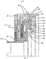
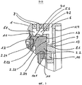
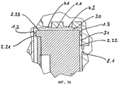
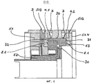
В варианте осуществления изобретения, показанном на фиг.1-4, ротор 2 установлен в статоре 1 посредством радиального аэростатического подшипника и упорного аэростатического подшипника. Как показано на фиг.1, ротор 2 имеет соединительные выступы 2а и соединительные впадины 2b для соединения с не показанным на чертеже вращательным приводом и, например, с радиолокационной антенной.In the embodiment of the invention shown in figures 1-4, the
С точки зрения высокочастотной техники статор 1 образует внешний проводник для коаксиального соединения с внутренним проводником 3. Статор 1 двумя радиальными, сложенными четвертьволновыми линиями известным способом соединен с ротором 2 без гальванического контакта. Ротор 2 в одном месте своей окружности имеет коаксиальное подключение для соединения с внутренним проводником 30 для съема или ввода высокочастотных сигналов.From the point of view of high-frequency technology, the
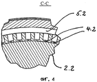
Ротор 2 имеет фланцевое кольцо 2.2. Фланцевое кольцо 2.2 входит в полый цилиндрический участок статора 1 и имеет кольцевую торцовую поверхность 2.21, противоположную ей кольцевую торцовую поверхность 2.22 и цилиндрическую окружную поверхность 2.23. Цилиндрическая окружная поверхность 2.23 вместе с боковой поверхностью 1.1 полого цилиндрического участка статора 1 ограничивает радиальный аэростатический подшипник. Как показано в увеличенном масштабе на фиг.3, в боковой поверхности 1.1 полого цилиндрического участка статора предусмотрены радиальные отверстия 4.1 и 4.2 для прохода воздуха, имеющие диаметр от 60 до 80 мкм и соединенные с вращающимися кольцевыми каналами 5.1 и 5.2, которые в свою очередь сообщаются с общим патрубком 6, по которому сжатый воздух подается от не показанного здесь источника. Кольцевые каналы 5.1 и 5.2 снаружи закрыты уплотнительными кольцами 7 круглого сечения или аналогичными уплотнениями.The
Радиальные отверстия 4.1 и 4.2 для прохода воздуха согласно фиг.4 равномерно распределены по окружности боковой поверхности 1.1 полого цилиндрического участка статора 1. Однако в определенных расчетных вариантах нагрузки может оказаться более предпочтительным неравномерное распределение отверстий для прохода воздуха.The radial holes 4.1 and 4.2 for the air passage according to FIG. 4 are evenly distributed around the circumference of the side surface 1.1 of the hollow cylindrical portion of the
В зависимости от толщины фланцевого кольца 2.2 в осевом направлении можно вместо двух параллельных рядов радиальных отверстий 4.1 и 4.2 для прохода воздуха предусмотреть только один ряд или более двух параллельных рядов таких радиальных отверстий для прохода воздуха.Depending on the thickness of the flange ring 2.2 in the axial direction, instead of two parallel rows of radial holes 4.1 and 4.2, for air passage, only one row or more than two parallel rows of such radial holes for air passage can be provided.
При вдувании сжатого воздуха через патрубок 6 между окружной поверхностью 2.23 фланцевого кольца 2.2 и боковой поверхностью 1.1 полого цилиндрического участка статора устанавливается по существу постоянный по окружности зазор радиального аэростатического подшипника шириной порядка 10-20 мкм.When blowing compressed air through the
Противоположные кольцевым торцовым поверхностям 2.21 и 2.22 кольцевые поверхности 1.2 и 1.3 полого цилиндрического участка статора 1 расположены на таком расстоянии друг от друга, чтобы между этими кольцевыми поверхностями и сопряженными поверхностями 2.21 и 2.22 по окружности оставался кольцевой зазор. Кольцевая торцовая поверхность 2.22 фланцевого кольца 2.2 ротора 2 вместе с противоположной кольцевой поверхностью 1.3 ограничивает в крышке 1.4 подшипника статора 1 упорный аэростатический подшипник. Для этого в кольцевой поверхности 1.3 предусмотрены осевые отверстия 8.1 для прохода воздуха согласно фиг.3, которые в данном случае равномерно распределены по окружности. Осевые отверстия 8.1 для прохода воздуха аналогично радиальным отверстиям 4.1 и 4.2 для прохода воздуха снабжаются сжатым воздухом из общего кольцевого канала 9. Кольцевой канал 9 снаружи закрыт кольцом 13 и сообщается с тем же патрубком 6 для сжатого воздуха, что и кольцевые каналы 5.1 и 5.2. Как и в случае радиального аэростатического подшипника, этот упорный аэростатический подшипник может содержать больше одного ряда отверстий для прохода воздуха. В определенных вариантах расчетных нагрузок эти отверстия могут быть также неравномерно распределены по окружности.The annular surfaces 1.2 and 1.3 of the hollow cylindrical section of the
Воздух, нагнетаемый через осевые отверстия 8.1 для прохода воздуха в зазор аэростатического подшипника, стремится переместить ротор 2 в осевом направлении. Этому перемещению противодействует набор равномерно распределенных по окружности крышки 1.4 статора 1 постоянных магнитов 10, намагниченных в осевом направлении и своей обращенной к ротору 2 поверхностью полюсов расположенных по существу заподлицо с кольцевой поверхностью 1.3 крышки 1.4 подшипника статора 1. Постоянные магниты 10 воздействуют на стальное кольцо 11, являющееся частью ротора 2, своим кольцевым пояском 11.1 входящее в расположенный по окружности фланцевого кольца паз 2.24 и соединенное геометрическим замыканием с фланцевым кольцом 2.2. Для компенсации различия в тепловом расширении материала ротора, который, в частности, может представлять собой легкий сплав, и стального кольца 11 его кольцевой поясок 11.1 свободно подвижен в проходящем по окружности пазу 2.24 и, как видно на фиг.2, разделен в одном месте своей окружности. Без стального кольца 11 можно обойтись, если сам ротор 2 или по меньшей мере его фланцевое кольцо 2.2 выполнены из ферромагнитного материала.The air pumped through the axial openings 8.1 for the passage of air into the gap of the aerostatic bearing tends to move the
На фиг.3а показан увеличенный фрагмент фиг.3, чтобы продемонстрировать утрированно увеличенную ширину зазора подшипников, а именно зазора радиального аэростатического подшипника 20 и зазора упорного аэростатического подшипника 31.Fig. 3a shows an enlarged fragment of Fig. 3 in order to demonstrate an exaggerated enlarged width of the bearing clearance, namely, the clearance of the radial
Воздух, выходящий из зазора радиального аэростатического подшипника 20 и зазора упорного аэростатического подшипника 31, отводится по общему выпускному каналу 12 (см. фиг.2).The air leaving the clearance of the radial
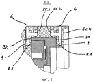
На фиг.5-7 показан второй вариант исполнения высокочастотного вращающегося соединения.5-7 show a second embodiment of a high frequency rotating joint.
Одинаковые детали имеют те же цифровые обозначения, что и на фиг.1-4, перед обозначениями деталей, имеющих соответствующее функциональное назначение, стоит цифра "5".Identical parts have the same numerical designations as in FIGS. 1-4, before the designations of parts having the corresponding functional purpose, there is a number “5”.
Второй вариант исполнения отличается от первого, с одной стороны, тем, что ротор 52 бесконтактно соединен со статором 51 не сложенной в радиальном направлении четвертьволновой линией, а прямой осевой четвертьволновой линией, и что, с другой стороны, радиальное фланцевое кольцо 52.2 ротора 52 здесь обеими сторонами установлено в аэростатические подшипники. Радиальный аэростатический подшипник с зазором 20 имеет ту же конструкцию, что и в варианте исполнения согласно фиг.1-4. Второй (левый) упорный аэростатический подшипник с зазором 32 выполнен по существу зеркально-симметричным первому (правому) упорному аэростатическому подшипнику, который в свою очередь соответствует упорному аэростатическому подшипнику в варианте, показанном на фиг.1-4. Для второго упорного аэростатического подшипника предусмотрен еще один выпускной канал 513.The second embodiment differs from the first, on the one hand, in that the
Хотя соединение в варианте исполнения по фиг.5-7 имеет большую конструктивную длину в осевом направлении, чем в варианте исполнения по фиг.1-4, но оно имеет меньший диаметр и, прежде всего, обходится без постоянных магнитов и соответствующей сопряженной детали в роторе.Although the connection in the embodiment of FIGS. 5-7 has a greater structural length in the axial direction than in the embodiment of FIGS. 1-4, it has a smaller diameter and, above all, dispenses with permanent magnets and the corresponding mating part in the rotor .
Claims (14)
Applications Claiming Priority (3)
| Application Number | Priority Date | Filing Date | Title |
|---|---|---|---|
| DE102007026431.5 | 2007-06-06 | ||
| DE102007026431A DE102007026431B4 (en) | 2007-06-06 | 2007-06-06 | HF rotary coupling with lambda / 4-line between stator and rotor |
| DE102007026431 | 2007-06-06 |
Publications (2)
| Publication Number | Publication Date |
|---|---|
| RU2008122449A RU2008122449A (en) | 2009-12-10 |
| RU2396643C2 true RU2396643C2 (en) | 2010-08-10 |
Family
ID=39719189
Family Applications (1)
| Application Number | Title | Priority Date | Filing Date |
|---|---|---|---|
| RU2008122449/09A RU2396643C2 (en) | 2007-06-06 | 2008-06-05 | High-frequency rotation connection with quarter-wave circuit between stator and rotor |
Country Status (12)
| Country | Link |
|---|---|
| US (1) | US7808346B2 (en) |
| EP (1) | EP2001076B1 (en) |
| JP (1) | JP4575971B2 (en) |
| KR (1) | KR101012179B1 (en) |
| CN (1) | CN101320824A (en) |
| AT (1) | ATE472833T1 (en) |
| CA (1) | CA2633230A1 (en) |
| DE (2) | DE102007026431B4 (en) |
| ES (1) | ES2347200T3 (en) |
| IL (1) | IL191924A (en) |
| PL (1) | PL2001076T3 (en) |
| RU (1) | RU2396643C2 (en) |
Families Citing this family (8)
| Publication number | Priority date | Publication date | Assignee | Title |
|---|---|---|---|---|
| US8636567B2 (en) * | 2008-04-29 | 2014-01-28 | Airgonomix, Llc | Damper to control fluid flow and associated methods |
| US8508320B2 (en) * | 2010-01-07 | 2013-08-13 | General Electric Company | Antenna mounting to a rotor antenna having radial and axial air bearings |
| FR2978305B1 (en) * | 2011-07-22 | 2013-07-12 | Nexter Systems | DEVICE FOR TRANSMITTING WIRELESS DATA BETWEEN A FIXED BRACKET AND A MOBILE SUPPORT AND APPLICATION OF SUCH A DEVICE FOR TRANSMITTING DATA BETWEEN A CHASSIS AND A TURRET |
| US10598222B2 (en) | 2012-01-03 | 2020-03-24 | New Way Machine Components, Inc. | Air bearing for use as seal |
| SG11201403813TA (en) | 2012-01-03 | 2014-09-26 | New Way Machine Components Inc | Air bearing for use as seal |
| CN104466306B (en) * | 2014-11-06 | 2017-04-19 | 北京遥测技术研究所 | Three-channel microwave rotary joint |
| CN105207034B (en) * | 2015-10-16 | 2018-02-13 | 中国电子科技集团公司第三十八研究所 | A kind of cable suitable for radar rotary transfer turns around device |
| PL3722668T3 (en) * | 2019-04-11 | 2022-01-10 | Dark Matter Gmbh | System comprising an illumination component |
Family Cites Families (16)
| Publication number | Priority date | Publication date | Assignee | Title |
|---|---|---|---|---|
| BE792731A (en) * | 1972-09-13 | 1973-03-30 | Elettronica Aster Srl | ROTATING JOINT WITH STEPS FOR WAVE GUIDE |
| US3914715A (en) * | 1974-06-26 | 1975-10-21 | Texas Instruments Inc | Coaxial ring rotary joint |
| US4233580A (en) * | 1976-11-23 | 1980-11-11 | Spinner Gmbh | Rotating coupler for transmitting high frequency energy |
| US4258365A (en) * | 1979-12-07 | 1981-03-24 | International Telephone And Telegraph Corporation | Around-the-mast rotary annular antenna feed coupler |
| GB2141289A (en) * | 1983-05-27 | 1984-12-12 | Marconi Co Ltd | Radars |
| JPS61105902A (en) * | 1984-10-30 | 1986-05-24 | Sony Corp | Rotary coupler |
| US5233320A (en) * | 1990-11-30 | 1993-08-03 | Evans Gary E | Compact multiple channel rotary joint |
| DE4403340A1 (en) | 1994-02-03 | 1995-08-10 | Heinzl Joachim | Method for producing at least one micro nozzle of an aerostatic bearing |
| US5748156A (en) * | 1994-02-28 | 1998-05-05 | Chaparral Communications | High-performance antenna structure |
| DE4436156C1 (en) * | 1994-10-10 | 1996-03-21 | Heinzl Joachim | Aerostatic bearing and method for manufacturing an aerostatic bearing |
| ES2235397T3 (en) * | 1998-04-15 | 2005-07-01 | Spinner Gmbh Elektrotechnische Fabrik | ROTATING COUPLING OF HF. |
| DE19953118A1 (en) * | 1999-11-04 | 2001-05-17 | Foehrenbach Manfred Gmbh | Drive module with bearing e.g. for machine tools, has coils geometrically arranged in stator so intermediate gaps are formed that are provided with air nozzles for blowing out air to produce air bearing for rotor |
| DE10037747A1 (en) | 2000-08-02 | 2002-03-07 | Schleifring Und Appbau Gmbh | Arrangement for contactless rotation transmission of high-frequency signals |
| DE10209776B3 (en) * | 2002-02-28 | 2004-04-29 | Carl Zeiss | Fluid rotary bearing for coordinate measurement device has membrane joined to bearing element by supports at distance from edge to bound volume subjected to pressure lower than fluid pressure |
| DE10210750B4 (en) * | 2002-03-12 | 2004-02-12 | Precise Präzisionsspindeln GmbH | High-speed spindle |
| US7014370B2 (en) * | 2003-04-25 | 2006-03-21 | Nuvisions International, Inc. | Bare fiber optical connecting devices |
-
2007
- 2007-06-06 DE DE102007026431A patent/DE102007026431B4/en not_active Expired - Fee Related
-
2008
- 2008-05-29 ES ES08009844T patent/ES2347200T3/en active Active
- 2008-05-29 EP EP08009844A patent/EP2001076B1/en not_active Not-in-force
- 2008-05-29 PL PL08009844T patent/PL2001076T3/en unknown
- 2008-05-29 AT AT08009844T patent/ATE472833T1/en active
- 2008-05-29 DE DE502008000860T patent/DE502008000860D1/en active Active
- 2008-06-03 IL IL191924A patent/IL191924A/en not_active IP Right Cessation
- 2008-06-03 CA CA002633230A patent/CA2633230A1/en not_active Abandoned
- 2008-06-04 JP JP2008146631A patent/JP4575971B2/en not_active Expired - Fee Related
- 2008-06-05 RU RU2008122449/09A patent/RU2396643C2/en not_active IP Right Cessation
- 2008-06-05 KR KR1020080052835A patent/KR101012179B1/en not_active IP Right Cessation
- 2008-06-06 CN CNA2008101089110A patent/CN101320824A/en active Pending
- 2008-06-06 US US12/134,407 patent/US7808346B2/en not_active Expired - Fee Related
Also Published As
| Publication number | Publication date |
|---|---|
| DE102007026431A1 (en) | 2008-12-24 |
| IL191924A (en) | 2012-04-30 |
| RU2008122449A (en) | 2009-12-10 |
| KR101012179B1 (en) | 2011-02-07 |
| US7808346B2 (en) | 2010-10-05 |
| US20080303614A1 (en) | 2008-12-11 |
| EP2001076B1 (en) | 2010-06-30 |
| PL2001076T3 (en) | 2010-09-30 |
| ES2347200T3 (en) | 2010-10-26 |
| CA2633230A1 (en) | 2008-12-06 |
| CN101320824A (en) | 2008-12-10 |
| ATE472833T1 (en) | 2010-07-15 |
| JP2009005348A (en) | 2009-01-08 |
| DE102007026431B4 (en) | 2009-04-23 |
| DE502008000860D1 (en) | 2010-08-12 |
| JP4575971B2 (en) | 2010-11-04 |
| IL191924A0 (en) | 2009-02-11 |
| KR20080107293A (en) | 2008-12-10 |
| EP2001076A1 (en) | 2008-12-10 |
Similar Documents
| Publication | Publication Date | Title |
|---|---|---|
| RU2396643C2 (en) | High-frequency rotation connection with quarter-wave circuit between stator and rotor | |
| EP1193370B1 (en) | Turbocharger rotor with alignment couplings | |
| CA2494737C (en) | Integrated oil transfer sleeve and bearing | |
| US7658545B2 (en) | Compliant foil-fluid bearing support arrangement | |
| CA2753819C (en) | Thermally decoupled bearing arrangement | |
| US20090134583A1 (en) | Dual seal assembly | |
| US20100171269A1 (en) | Monitoring of a Sealing Arrangement, Particularly of a Gas Compressor or Gas Expander | |
| CN108930776B (en) | Spur gear device, transmission mechanism and wind energy facility | |
| KR20050039660A (en) | Radial rotary transfer assembly | |
| US10260604B2 (en) | Speed increaser | |
| JP2019507853A (en) | Turbocharger sealing device | |
| WO1997005419A1 (en) | Expansion unit for piping adjustment | |
| EP3258123B1 (en) | Floating bush bearing device and supercharger provided with same | |
| US20150260194A1 (en) | Turbo Compressor | |
| US20040051604A1 (en) | Device for carrying out the non-contact rotational transmission of high-frequency | |
| JP6559717B2 (en) | mechanical seal | |
| JP2006283673A (en) | Scroll type fluid machine | |
| CN220957309U (en) | Gas-liquid slip ring | |
| CN218992349U (en) | Combined structure silicon carbide mechanical sealing device | |
| RU2696922C1 (en) | Sealed coupling device for fluid medium | |
| RU131828U1 (en) | RADIAL BEARING ASSEMBLY | |
| JP2016019396A (en) | Joint structure of superconducting motor | |
| GB2357321A (en) | Electromagnetic-pneumatic positioning device. | |
| US2126280A (en) | Air compressor | |
| CN114165437A (en) | Scroll compressor having a plurality of scroll members |
Legal Events
| Date | Code | Title | Description |
|---|---|---|---|
| MM4A | The patent is invalid due to non-payment of fees |
Effective date: 20110606 |