RU2395103C1 - Device for measuring signal spectra of response of atomic elements to penetrating radiation - Google Patents
Device for measuring signal spectra of response of atomic elements to penetrating radiation Download PDFInfo
- Publication number
- RU2395103C1 RU2395103C1 RU2009112572/28A RU2009112572A RU2395103C1 RU 2395103 C1 RU2395103 C1 RU 2395103C1 RU 2009112572/28 A RU2009112572/28 A RU 2009112572/28A RU 2009112572 A RU2009112572 A RU 2009112572A RU 2395103 C1 RU2395103 C1 RU 2395103C1
- Authority
- RU
- Russia
- Prior art keywords
- response
- filter
- signal spectra
- radiation
- elements
- Prior art date
Links
Images

Landscapes
- Measurement Of Radiation (AREA)
Abstract
Description
Изобретение относится к ядерной физике и может быть использовано в научной измерительной аппаратуре, а также при разработке средств оперативного обнаружения и идентификации контрабандных материалов при таможенном досмотре, патрулировании государственных границ.The invention relates to nuclear physics and can be used in scientific measuring equipment, as well as in the development of tools for the rapid detection and identification of contraband materials during customs inspection, patrolling state borders.
В настоящее время для экспресс-анализа контрабандных материалов развиваются методы их активного облучения с целью увеличения скорости деления и последующей регистрации сигналов откликов либо мгновенной, либо запаздывающей реакции веществ на проникающее облучение. При этом выявление сигнатурных признаков контрабандного материала базируется на измерении амплитудно-временных зависимостей между мгновенной и запаздывающей реакцией вещества на облучение. Для идентификации атомных элементов используют корреляционный анализ амплитудно-временных сигналов. Преобразование проникающей радиации в электрический сигнал осуществляют посредством детекторов-дискриминаторов.Currently, for the rapid analysis of contraband materials, methods are being developed for their active exposure in order to increase the rate of division and subsequent recording of response signals of either instant or delayed response of substances to penetrating radiation. In this case, the identification of signature features of contraband material is based on measuring the amplitude-time dependencies between the instantaneous and delayed response of the substance to radiation. To identify atomic elements, a correlation analysis of amplitude-time signals is used. The conversion of penetrating radiation into an electrical signal is carried out by means of discriminating detectors.
Известно "Устройство для регистрации гамма-нейтронного излучения" - Патент RU №2264674, H01J, 47/02, G01T, 1/185, 2003 г. - аналог. Устройство для регистрации гамма-нейтронного излучения включает цилиндрическую ионизационную камеру с экранирующей сеткой, источник высоковольтного питания, зарядочувствительный усилитель, в качестве катода использован корпус детектора с внешним изоляционным покрытием, при этом в качестве рабочего вещества использован сверхчистый ксенон, при давлении 40-50 атм и соответственно с плотностью 0.3-0.6 г/см3 с добавлением водорода в количестве 0.2-0.3% от общего содержания ксенона, кроме того, металлическая экранирующая сетка, находящаяся внутри ионизационной камеры, имеет степень неэффективности экранирования σ≈(3÷5)%.It is known "Device for detecting gamma-neutron radiation" - Patent RU No. 2264674, H01J, 47/02, G01T, 1/185, 2003 - analogue. A device for detecting gamma-neutron radiation includes a cylindrical ionization chamber with a shielding grid, a high-voltage power supply, a charge-sensitive amplifier, the detector case with an external insulating coating is used as a cathode, and ultrapure xenon is used as a working medium at a pressure of 40-50 atm and respectively, with a density of 0.3-0.6 g / cm 3 with the addition of hydrogen in an amount of 0.2-0.3% of the total xenon content, in addition, a metal shielding mesh inside ionization chamber, has a degree of screening inefficiency σ≈ (3 ÷ 5)%.
Сигнал на выходе устройства-аналога пропорционален суммарной мощности потока гамма-нейтронного излучения, что не позволяет, в последующих трактах, разделить этот поток на составляющие по энергетическому спектру отдельных гамма-квантов.The signal at the output of the analog device is proportional to the total power of the gamma-neutron radiation flux, which does not allow, in subsequent paths, to divide this flux into components according to the energy spectrum of individual gamma-rays.
Известны промышленные разработки детекторов-измерителей спектров уровней мощности гамма-излучения: блоки детектирования БДРС, БДЕГ-19П, гамма-детектор-сцинтиллятор CsJ(TI) - фотодиод ФД1001 (http://www.detector.org.ua/detectors.html) - аналоги.Known industrial developments of detectors-measuring spectra of gamma radiation power levels: BDS detection units, BDEG-19P, CsJ (TI) gamma-detector-scintillator - FD1001 photodiode (http://www.detector.org.ua/detectors.html) - analogues.
Недостатками аналогов являются:The disadvantages of analogues are:
- невозможность однозначного измерения формы энергетического спектра сигнала отклика;- the impossibility of unambiguous measurement of the shape of the energy spectrum of the response signal;
- малое эффективное сечение (размер апертуры) датчика-преобразователя и, как следствие, - недостаточная чувствительность измерителей.- small effective cross-section (aperture size) of the transducer-sensor and, as a result, - insufficient sensitivity of the meters.
Ближайшим аналогом к заявляемому техническому решению является "Сцинтилляционный детектор с оптоволоконным съемом информации" разработки ГНЦ ИФВЭ (г.Протвино и ФИАН РАН), серийно производимый ГНЦ ИФВЭ [см. материалы 30-й ВККЛ, Санкт-Петербург, 2008 г.] (http://theory.asu.ru/~raikin/Physics/PCR/2008_StPetersberg/RCRC2008/PROC/E AS/EAS_20.pdf). Он представляет собой двухслойную сборку сцинтилляционных пластин общей площадью 1 м2. Каждый слой собран из пластин 20×20×0.5 см3. Светосбор осуществляется с помощью спектросмещающих волокон - файберов. В каждой пластине имеется 4 канавки с шагом 3.6 см глубиной 2.2 мм на расстоянии 4.6 см от краев. В эти канавки вклеены файберы диаметром 1 мм. Концы файберов собраны в жгут, проклеены и отполированы. Торец жгута закреплен вплотную к фотокатоду фотоэлектронного умножителя.The closest analogue to the claimed technical solution is the “Scintillation detector with fiber optic information retrieval” developed by SSC IHEP (Protvino and LPI RAS), commercially produced by SSC IHEP [see materials of the 30th VKCL, St. Petersburg, 2008] (http://theory.asu.ru/~raikin/Physics/PCR/2008_StPetersberg/RCRC2008/PROC/E AS / EAS_20.pdf). It is a two-layer assembly of scintillation plates with a total area of 1 m 2 . Each layer is assembled from plates of 20 × 20 × 0.5 cm 3 . Light collection is carried out using spectroscopic fibers - fibers. Each plate has 4 grooves with a pitch of 3.6 cm and a depth of 2.2 mm at a distance of 4.6 cm from the edges.
Недостатком ближайшего аналога является невозможность выделить энергетический спектр исходного сигнала на выходе счетчика после усиления общего светового потока фотоэлектронным умножителем.The disadvantage of the closest analogue is the inability to select the energy spectrum of the original signal at the output of the counter after amplification of the total light flux by a photoelectronic multiplier.
Задача, решаемая заявляемым измерителем, состоит в достоверной регистрации энергетического спектра исходного сигнала отклика атомного элемента на зондирующее облучение путем последовательного пропорционального преобразования потока радиации в ультрафиолетовый спектр, а ультрафиолетового спектра в световой поток видимого диапазона с последующим измерением амплитуды спектральных составляющих пропусканием светового потока через линейно-перестраиваемый акустооптический фильтр с регулируемой длительностью импульса пилообразного напряжения развертки.The problem solved by the claimed meter consists in reliable recording of the energy spectrum of the initial signal of the response of the atomic element to probing irradiation by successive proportional conversion of the radiation flux into the ultraviolet spectrum, and the ultraviolet spectrum into the visible light flux, followed by measuring the amplitude of the spectral components by transmitting the light flux through a linear tunable acousto-optic filter with adjustable sawtooth pulse width scan voltage.
Техническое решение задачи осуществляется тем, что измеритель спектров сигналов откликов атомных элементов на проникающее облучение, содержащий сборку сцинтилляционных пластин, преобразующих поток радиации отклика в спектр ультрафиолетового излучения, волокна-файберы, уложенные в профильные канавки пластин, спектросмещающие ультрафиолетовое излучение в спектр видимого диапазона, торец жгута файберов, преобразователь светового потока в электрический сигнал, дополнительно к торцу файберов приклеена светособирающая линза, формирующая диаметр светового пучка для ввода его в акустооптический фильтр, генератор накачки фильтра с подключенными к нему реактивным элементом и генератором пилообразного напряжения для линейного изменения частоты настройки фильтра, последовательно подключенные к выходу фильтра лавинный фотодиод, аналого-цифровой преобразователь, буферное запоминающее устройство и компьютер, осуществляющий визуализацию регистрируемых спектров сигналов, а также синхронизацию работы элементов устройства и регулирование длительности импульсов генератора пилообразного напряжения путем закладываемой в компьютер телекоммуникационной программы.The technical solution of the problem is carried out by the fact that the measuring instrument for the spectra of the responses of atomic elements to penetrating radiation, containing an assembly of scintillation plates, converting the response radiation flux into the ultraviolet radiation spectrum, fiber fibers laid in profile grooves of the plates, spectrally displacing ultraviolet radiation into the visible spectrum, end a fiber bundle, a light flux to electric signal converter, in addition to a fiber end, a light-collecting lens is glued, forming the diameter of the light beam for entering it into an acousto-optic filter, a filter pump generator with a reactive element and a sawtooth voltage generator for linearly changing the filter tuning frequency, an avalanche photodiode, an analog-to-digital converter, a buffer memory and a computer, connected in series to the output of the filter visualizing the recorded spectra of signals, as well as synchronizing the operation of the elements of the device and controlling the pulse duration of the generator sawtooth voltage by inserting a telecommunication program into the computer.
Изобретение поясняется чертежами, где:The invention is illustrated by drawings, where:
фиг.1 - функциональная схема измерителя;figure 1 - functional diagram of the meter;
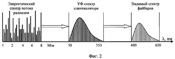
фиг.2 - последовательность спектров сигналов: 1) энергетический спектр излучения отклика, 2) спектр ультрафиолетового преобразования энергетического спектра сцинтилляционными пластинами, 3) спектр видимого диапазона на выходе файберов;figure 2 is a sequence of signal spectra: 1) the energy spectrum of the response radiation, 2) the ultraviolet conversion spectrum of the energy spectrum with scintillation plates, 3) the spectrum of the visible range at the output of the fibers;
фиг.3 - динамика перестройки акустооптического фильтра генератором накачки;figure 3 - dynamics of the tuning of the acousto-optical filter by the pump generator;
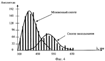
фиг.4 - реализации регистрируемых спектров атомных элементов.figure 4 - implementation of the recorded spectra of atomic elements.
Измеритель спектров сигналов откликов атомных элементов на проникающее облучение, фиг.1, содержит сборку сцинтилляционных пластин 1, волокна-файберы 2, уложенные в профильные канавки пластин, собранные в жгут 3 отводы оптического волокна от файберов, светособирающая линза 4 для ввода светового потока в акустооптический фильтр 5, генератор накачки 6 для перестройки частоты фильтра, реактивный элемент 7 генератора накачки 6, генератор пилообразного напряжения 8 для линейной девиации частоты генератора накачки, лавинный фотодиод 9, аналого-цифровой преобразователь 10, буферное запоминающее устройство 11, персональный компьютер 12 в составе элементов: процессор 13, оперативное запоминающее устройство 14, винчестер 15, дисплей 16, принтер 17, клавиатура 18. Синхронизация работы элементов измерителя осуществляется телекоммуникационной программой, записанной в винчестер 15. Телекоммуникационная программа реализует функции: запуск генератора зондирующего пучка с регулируемой длительностью и скважностью пачки зондирующих импульсов, регулирование длительности импульса пилообразного напряжения в зависимости от длительности пачки зондирующих импульсов, пересылку оцифрованных измерений из АЦП 10 и буферного ЗУ 11 в ОЗУ 14 для обработки зарегистрированных спектров сигналов на компьютере 12.The meter of the spectra of the signals of the responses of atomic elements to penetrating radiation, Fig. 1, contains an assembly of
Динамика взаимодействия элементов измерителя состоит в следующем. Атомные элементы отличаются энергией связи ядра, высвобождаемой при ядерных реакциях. Диапазон энергии излучаемых гамма-квантов и частиц занимает интервал от 1.1 МэВ до 8.8 МэВ. Энергия связи ядер атомных элементов и их изотопов иллюстрируется таблицей 1.The dynamics of the interaction of the elements of the meter is as follows. Atomic elements are distinguished by the binding energy of the nucleus released during nuclear reactions. The energy range of emitted gamma rays and particles occupies the interval from 1.1 MeV to 8.8 MeV. The binding energy of the nuclei of atomic elements and their isotopes is illustrated in table 1.
Селектируемыми признаками при идентификации атомных элементов могут быть:Selectable features in the identification of atomic elements can be:
- энергетический спектр частиц и квантов при распаде ядра;- the energy spectrum of particles and quanta in the decay of the nucleus;
- соотношение между спектрами мгновенного и запаздывающего излучения;- the ratio between the spectra of instantaneous and delayed radiation;
- форма сигнала регистрируемого спектра, т.е. амплитудные соотношения между спектральными линиями.- waveform of the recorded spectrum, i.e. amplitude relationships between spectral lines.
В заявленном измерителе для измерения формы спектра сигналов откликов атомных элементов используют последовательное пропорциональное спектросмещение (фиг.2):In the inventive meter to measure the shape of the spectrum of the signals of the responses of atomic elements using sequential proportional spectral displacement (figure 2):
- энергетического спектра сигнала отклика в спектр ультрафиолетового излучения посредством сборки (1) сцинтилляционных пластин из твердого раствора антрацена (С14Н10) в полистироле, дающих максимальный световой выход. Поскольку интенсивность световой вспышки пропорциональна энергии, потерянной частицей, то данная сборка используется в качестве первичного спектрометра;- the energy spectrum of the response signal to the ultraviolet radiation spectrum by assembling (1) scintillation plates from anthracene solid solution (C 14 H 10 ) in polystyrene, giving the maximum light output. Since the intensity of the light flash is proportional to the energy lost by the particle, this assembly is used as a primary spectrometer;
- спектра ультрафиолетового излучения в спектр видимого диапазона посредством оптического волокна-файбера 2.- the spectrum of ultraviolet radiation in the spectrum of the visible range by means of an optical fiber-
Поверхность файберов покрыта тонким слоем вещества люмогена, преобразующего УФИ в видимый диапазон. Типы файберов (конверторов), преобразующих УФИ (13-350 нм) в видимый диапазон (405-610 нм) (см. http://www.metrolux.de/contenido/cms/uv-and-ir-converter/)The surface of the fibers is covered with a thin layer of lumogen substance that converts UV radiation into the visible range. Types of fibers (converters) that convert UV light (13-350 nm) into the visible range (405-610 nm) (see http://www.metrolux.de/contenido/cms/uv-and-ir-converter/)
Спектр видимого диапазона посредством светособирающей линзы 4 преобразуют в световой пучок диаметром порядка 5 мм для ввода в перестраиваемый акустооптический фильтр 5 типа (промышленные разработки) СВ FOTF (Aurora), LAOTF (Bellcore) с полосой пропускания на уровне 3 дБ (1…1,6 нм) [см., например, Иванов А.Б. Волоконная оптика: компоненты системы передачи, измерения. - М: Компания Сайрус Системс, 1999, с.180-182].The spectrum of the visible range by means of a light-collecting
Акустооптический фильтр представляет собой кристалл (пьезоэлектрик), в котором под воздействием СВЧ-генератора накачки в диапазоне 60-70 МГц наблюдается анизотропная дифракция Брегга, т.е. формируется дифракционная решетка с изменяющимся показателем преломления, благодаря чему достигается перестраиваемая фильтрация.An acousto-optic filter is a crystal (piezoelectric) in which anisotropic Bragg diffraction is observed under the influence of a microwave pump generator in the range of 60-70 MHz, i.e. a diffraction grating is formed with a variable refractive index, due to which tunable filtration is achieved.
Линейную девиацию частоты СВЧ-генераторов метрового диапазона волн (60…70 МГц) осуществляют подключением реактивного элемента (типа реактивной лампы) по схеме [см. "Справочник по радиоэлектронике" под редакцией А.А.Куликовского, М.: Энергия, 1968. - с.50, рис.12-78, Реактивная лампа]. Девиация частоты достигается подачей дополнительного смещения на сетку в виде пилообразного напряжения развертки.The linear frequency deviation of microwave generators of the meter wavelength range (60 ... 70 MHz) is carried out by connecting a reactive element (such as a reactive lamp) according to the scheme [see "Handbook of Radio Electronics" edited by A.A. Kulikovsky, Moscow: Energia, 1968. - p.50, Fig. 12-78, Reactive lamp]. Frequency deviation is achieved by applying an additional bias to the grid in the form of a sawtooth sweep voltage.
Генератор пилообразного напряжения развертки с возможностью подачи на его вход синхронизирующих импульсов [см. там же "Справочник по радиоэлектронике", с.238, рис.15-52].A ramp voltage generator with the possibility of applying synchronizing pulses to its input [see ibid., “Handbook of Radio Electronics”, p.238, Fig. 15-52].
Динамика перестройки акустооптического фильтра накачкой его СВЧ-генератором с девиацией частоты пилообразными импульсами развертки иллюстрируется диаграммами фиг.3.The dynamics of the tuning of the acousto-optical filter by pumping it with a microwave generator with frequency deviation by sawtooth sweep pulses is illustrated by the diagrams of Fig. 3.
Другие элементы устройства выполнены на серийных промышленных разработках: лавинный фотодиод типа APD (чувствительность ~10-15 относительно темнового тока), аналого-цифровой преобразователь, микросборка П-267, буферное запоминающее устройство, микросборка ЛА-20 [см. Якубовский Б. и др. цифровые и аналоговые интегральные микросхемы. Справочник. М.: Радио и связь, 1990].Other elements of the device were made on serial industrial developments: an avalanche photodiode of the APD type (sensitivity ~ 10 -15 relative to the dark current), analog-to-digital converter, P-267 microassembly, buffer storage device, LA-20 microassembly [see Yakubovsky B. et al. Digital and analog integrated circuits. Directory. M .: Radio and communications, 1990].
Поскольку точность синхронизации элементов устройства должна составлять нс, телекоммуникационная программа реализована на специальном быстродействующем компьютере типа семейства компьютеров Ultra компании Sun Microsystems (НИИ системных исследований РАН) [см. http://www.solariscentral.org].Since the accuracy of synchronization of the elements of the device should be ns, the telecommunication program is implemented on a special high-speed computer such as the Sun Microsystems Ultra family of computers (Scientific Research Institute for System Studies of the Russian Academy of Sciences) [see http://www.solariscentral.org].
Реализации зарегистрированных спектров сигналов откликов в виде амплитудно-частотных характеристик видимого диапазона иллюстрируется графиками фиг.4.The implementation of the recorded spectra of response signals in the form of amplitude-frequency characteristics of the visible range is illustrated by the graphs of Fig. 4.
Эффективность измерителя определяется достоверностью идентификации атомного элемента. Имеется возможность набора статистических данных по формам АЧХ-спектров для создания базы эталонных сигналов. При наличии эталонной базы достоверную идентификацию атомных элементов проводят по амплитуде, длительности и форме, что превосходит известные аналоги.The effectiveness of the meter is determined by the reliability of the identification of the atomic element. There is the possibility of collecting statistical data on the forms of frequency response spectra to create a base of reference signals. In the presence of a reference base, reliable identification of atomic elements is carried out by amplitude, duration and shape, which exceeds the known analogues.
Claims (1)
Priority Applications (1)
| Application Number | Priority Date | Filing Date | Title |
|---|---|---|---|
| RU2009112572/28A RU2395103C1 (en) | 2009-04-07 | 2009-04-07 | Device for measuring signal spectra of response of atomic elements to penetrating radiation |
Applications Claiming Priority (1)
| Application Number | Priority Date | Filing Date | Title |
|---|---|---|---|
| RU2009112572/28A RU2395103C1 (en) | 2009-04-07 | 2009-04-07 | Device for measuring signal spectra of response of atomic elements to penetrating radiation |
Publications (1)
| Publication Number | Publication Date |
|---|---|
| RU2395103C1 true RU2395103C1 (en) | 2010-07-20 |
Family
ID=42686082
Family Applications (1)
| Application Number | Title | Priority Date | Filing Date |
|---|---|---|---|
| RU2009112572/28A RU2395103C1 (en) | 2009-04-07 | 2009-04-07 | Device for measuring signal spectra of response of atomic elements to penetrating radiation |
Country Status (1)
| Country | Link |
|---|---|
| RU (1) | RU2395103C1 (en) |
Citations (3)
| Publication number | Priority date | Publication date | Assignee | Title |
|---|---|---|---|---|
| RU2140092C1 (en) * | 1998-07-22 | 1999-10-20 | Научно-исследовательский институт импульсной техники | Gear recording form and spatial position of sources of ionizing radiation |
| RU2264674C2 (en) * | 2003-09-08 | 2005-11-20 | Московский инженерно-физический институт (государственный университет) | Gamma-neutron radiation recorder |
| US7297959B2 (en) * | 2003-11-07 | 2007-11-20 | Xradia, Inc. | Lens bonded X-ray scintillator system and manufacturing method therefor |
-
2009
- 2009-04-07 RU RU2009112572/28A patent/RU2395103C1/en not_active IP Right Cessation
Patent Citations (3)
| Publication number | Priority date | Publication date | Assignee | Title |
|---|---|---|---|---|
| RU2140092C1 (en) * | 1998-07-22 | 1999-10-20 | Научно-исследовательский институт импульсной техники | Gear recording form and spatial position of sources of ionizing radiation |
| RU2264674C2 (en) * | 2003-09-08 | 2005-11-20 | Московский инженерно-физический институт (государственный университет) | Gamma-neutron radiation recorder |
| US7297959B2 (en) * | 2003-11-07 | 2007-11-20 | Xradia, Inc. | Lens bonded X-ray scintillator system and manufacturing method therefor |
Similar Documents
| Publication | Publication Date | Title |
|---|---|---|
| Zhang et al. | Design of a high dynamic range photomultiplier base board for the BGO ECAL of DAMPE | |
| CN113419270B (en) | Online filter stack spectrometer | |
| Sweany et al. | Interaction position, time, and energy resolution in organic scintillator bars with dual-ended readout | |
| Stoykov et al. | A SiPM-based ZnS: 6LiF scintillation neutron detector | |
| Vitullo et al. | Developing and testing a miniature fiber-coupled scintillator for in-core neutron counting in CROCUS | |
| Chichester et al. | Comparison of BCF-10, BCF-12, and BCF-20 scintillating fibers for use in a 1-dimensional linear sensor | |
| Anfimov et al. | Study of silicon photomultiplier performance at different temperatures | |
| Mosset et al. | A 16-ch module for thermal neutron detection using ZnS: 6LiF scintillator with embedded WLS fibers coupled to SiPMs and its dedicated readout electronics | |
| Yu et al. | A prototype of the SiPM readout scintillator neutron detector for the engineering material diffractometer of CSNS | |
| EP3321714A1 (en) | Radiation monitor | |
| CN104730564A (en) | Ultrafast gamma ray energy spectrum measuring instrument based on scintillating-fiber array | |
| RU2395103C1 (en) | Device for measuring signal spectra of response of atomic elements to penetrating radiation | |
| US4542290A (en) | Apparatus for recording emissions from a rapidly generated plasma from a single plasma producing event | |
| Biller et al. | Measurements of photomultiplier single photon counting efficiency for the Sudbury Neutrino Observatory | |
| CN106772539B (en) | A scintillation detection system and method for measuring weak gamma pulses | |
| Hildebrandt et al. | Detection of thermal neutrons using ZnS (Ag): 6LiF neutron scintillator read out with WLS fibers and SiPMs | |
| Muralithar et al. | A charged particle detector array for detection of light charged particles from nuclear reactions | |
| Avvakumov et al. | Spontaneous light emission from fibers in MINOS | |
| Rosa et al. | Design solutions for the hodoscope of the magnetic proton recoil neutron spectrometer of the SPARC tokamak | |
| RU2402043C1 (en) | Method of detecting fissile materials | |
| Yu et al. | Performance test and qualification of the photomultiplier tube for the whole production of LHAASO-ED | |
| CN210803729U (en) | An experimental setup for measuring the lifetime of cosmic ray muons | |
| Tardocchi et al. | The monitoring system of a high performance fusion neutron spectrometer | |
| Pappalardo et al. | Low-cost radioactivity monitoring with scintillating fibers and silicon photomultipliers | |
| Zhang et al. | The development of a high granular crystal calorimeter prototype of VLAST |
Legal Events
| Date | Code | Title | Description |
|---|---|---|---|
| MM4A | The patent is invalid due to non-payment of fees |
Effective date: 20110408 |
|
| NF4A | Reinstatement of patent |
Effective date: 20120420 |
|
| MM4A | The patent is invalid due to non-payment of fees |
Effective date: 20140408 |