RU2394626C2 - Filtration device to filter water and other fluids - Google Patents
Filtration device to filter water and other fluids Download PDFInfo
- Publication number
- RU2394626C2 RU2394626C2 RU2007143559/15A RU2007143559A RU2394626C2 RU 2394626 C2 RU2394626 C2 RU 2394626C2 RU 2007143559/15 A RU2007143559/15 A RU 2007143559/15A RU 2007143559 A RU2007143559 A RU 2007143559A RU 2394626 C2 RU2394626 C2 RU 2394626C2
- Authority
- RU
- Russia
- Prior art keywords
- glass
- filtering device
- water
- cup
- cartridge
- Prior art date
Links
Images

Classifications
-
- C—CHEMISTRY; METALLURGY
- C02—TREATMENT OF WATER, WASTE WATER, SEWAGE, OR SLUDGE
- C02F—TREATMENT OF WATER, WASTE WATER, SEWAGE, OR SLUDGE
- C02F1/00—Treatment of water, waste water, or sewage
- C02F1/001—Processes for the treatment of water whereby the filtration technique is of importance
- C02F1/003—Processes for the treatment of water whereby the filtration technique is of importance using household-type filters for producing potable water, e.g. pitchers, bottles, faucet mounted devices
-
- C—CHEMISTRY; METALLURGY
- C02—TREATMENT OF WATER, WASTE WATER, SEWAGE, OR SLUDGE
- C02F—TREATMENT OF WATER, WASTE WATER, SEWAGE, OR SLUDGE
- C02F2307/00—Location of water treatment or water treatment device
- C02F2307/04—Location of water treatment or water treatment device as part of a pitcher or jug
Abstract
Description
Настоящее изобретение относится к фильтрующему устройству для фильтрования воды и вообще жидкостей, содержащему отличительные признаки, изложенные в ограничительной части основного пункта формулы изобретения.The present invention relates to a filtering device for filtering water and in general liquids, containing the distinguishing features set forth in the limiting part of the main claim.
Такие устройства известны и широко распространены на рынке благодаря их способности обеспечивать на бытовом уровне питьевой водой, которая имеет улучшенные свойства - как химические свойства (соленость, жесткость и т.д.), так и органолептические свойства - по сравнению с водопроводной водой.Such devices are known and widely distributed on the market due to their ability to provide drinking water at the household level, which has improved properties - both chemical properties (salinity, hardness, etc.) and organoleptic properties - compared to tap water.
Типичный пример таких устройств описан в патентном документе WO 9613318 на имя данного заявителя. Описанное в нем фильтрующее устройство относится к типу, имеющему кувшин для фильтрования самотеком, в котором вода, вводимая в верхний резервуар, медленно проходит в нижний резервуар, перемещаясь через фильтровальный патрон, который содержит фильтрующие элементы с активированным углем и ионообменным веществом.A typical example of such devices is described in patent document WO 9613318 in the name of this applicant. The filter device described therein is of a type having a gravity filter jug, in which water introduced into the upper tank slowly passes into the lower tank, moving through a filter cartridge that contains filter elements with activated carbon and an ion-exchange substance.
Фильтрующая способность патрона зависит от различных факторов, среди которых важное значение имеет время контакта между фильтрующим средством и фильтруемой водой. Прохождение воды в патрон осуществляется самотеком, и следовательно, поток, понимаемый как расход за единицу времени, изменяется в соответствии с перепадом давления до и после по ходу патрона, который, в свою очередь, зависит как от уровня воды в верхнем резервуаре для помещения фильтруемой воды, так и от уровня фильтрованной воды в нижнем резервуаре.The filtering ability of the cartridge depends on various factors, among which the contact time between the filtering agent and filtered water is important. The passage of water into the cartridge is carried out by gravity, and therefore, the flow, understood as the flow rate per unit of time, changes in accordance with the pressure drop before and after along the cartridge, which, in turn, depends on the water level in the upper reservoir for placing filtered water , and from the level of filtered water in the lower tank.
Следовательно, фильтрованная вода обладает изменяющимися свойствами во время фазы фильтрования. На рынке известен фильтровальный кувшин, в котором стакан для помещения в него фильтровального патрона закрыт снизу и имеет выпускное отверстие для фильтрованной воды, которое расположено вблизи верхнего резервуара. Таким образом, значительно исключается влияние степени наполнения нижнего резервуара на поток фильтрованной воды.Consequently, filtered water has variable properties during the filtering phase. A filter jug is known on the market in which the glass for placing the filter cartridge into it is closed from below and has an outlet for filtered water, which is located near the upper reservoir. Thus, the influence of the degree of filling of the lower reservoir on the flow of filtered water is significantly eliminated.
Однако это техническое решение имеет некоторые очевидные недостатки. Первый недостаток заключается в том, что, хотя постепенное наполнение нижнего резервуара не влияет на расход в выпускном отверстии для фильтрованной воды, тем не менее расход является неравномерным и непостоянным в отношении изменяющегося уровня в верхнем резервуаре. Кроме того, стакан для приема патрона не доступен снизу, что затрудняет удаление использованного патрона во время его замены. Следовательно, необходимо части патрона, выступающей в верхний резервуар, придавать такие размеры и формы, которые позволяли бы захватывать и удалять его, что в дополнение к определению общей конфигурации патрона влияет на его размеры и взаимозаменяемость с патронами от других изготовителей.However, this technical solution has some obvious disadvantages. The first drawback is that, although the gradual filling of the lower reservoir does not affect the flow rate in the filtered water outlet, the flow rate is non-uniform and inconsistent with respect to the changing level in the upper reservoir. In addition, the glass for receiving the cartridge is not accessible from below, which makes it difficult to remove the used cartridge during its replacement. Therefore, it is necessary to give the part of the cartridge protruding into the upper tank such dimensions and shapes that would allow it to be captured and removed, which in addition to determining the general configuration of the cartridge affects its size and interchangeability with cartridges from other manufacturers.
Другой недостаток заключается в трудности очистки гнезда под патрон во время ухода за фильтрующим устройством. Так как стакан закрыт снизу, то он подобным же образом является недоступным.Another disadvantage is the difficulty in cleaning the cartridge housing while maintaining the filter device. Since the glass is closed from below, it is likewise inaccessible.
Другой недостаток касается возможности регулирования фильтруемого потока. Это может потребоваться, например, для того, чтобы привести расход в соответствие с показателями жесткости или органолептическими свойствами фильтруемой воды. Например, в летний период вода может сильно пахнуть хлором, для нейтрализации которого может потребоваться большее время фильтрования, чем это необходимо в зимний период.Another disadvantage concerns the ability to control the filtered stream. This may be required, for example, in order to bring the flow rate in line with the hardness indicators or organoleptic properties of the filtered water. For example, in the summer, water can smell strongly of chlorine, which may require a longer filtration time to neutralize than is necessary in the winter.
Согласно настоящему изобретению эта техническая проблема решается посредством фильтрующего устройства для фильтрования воды и вообще жидкостей, которое конструктивно и функционально выполнено с возможностью устранения недостатков, изложенных со ссылкой на описанный прототип.According to the present invention, this technical problem is solved by means of a filtering device for filtering water and in general liquids, which is structurally and functionally configured to eliminate the disadvantages set forth with reference to the described prototype.
Эта проблема решается изобретением посредством фильтрующего устройства для фильтрования воды и вообще жидкостей, которое выполнено согласно прилагаемой формуле изобретения.This problem is solved by the invention by means of a filtering device for filtering water and in general liquids, which is made in accordance with the attached claims.
Отличительные признаки и преимущества изобретения будут лучше поняты из нижеследующего подробного описания некоторых из предпочтительных неограничительных вариантов его осуществления, показанных лишь в качестве примера, со ссылкой на сопровождающие чертежи, на которых:The distinguishing features and advantages of the invention will be better understood from the following detailed description of some of the preferred non-limiting embodiments thereof, shown by way of example only, with reference to the accompanying drawings, in which:
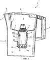
фиг.1 - продольный разрез фильтрующего устройства согласно первому варианту осуществления этого изобретения, при этом устройство встроено в кувшин;figure 1 is a longitudinal section of a filtering device according to the first embodiment of this invention, while the device is integrated in a jug;
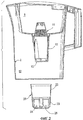
фиг.2 - вид кувшина на фиг.1 с частичным пространственным разделением деталей;figure 2 is a view of the jug in figure 1 with a partial spatial separation of parts;
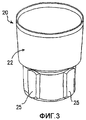
фиг.3 - вид в перспективе сверху части кувшина на фиг.1;figure 3 is a perspective view from above of a part of the jug in figure 1;
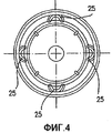
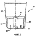
фиг.4 и 5 - соответственно поперечный и продольный разрезы части на фиг.3;4 and 5, respectively, transverse and longitudinal sections of the part in figure 3;
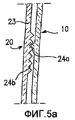
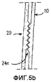
фиг.5а и 5b - виды в увеличенном масштабе соответствующих вариантов конструкции кувшина на фиг.1;FIGS. 5a and 5b are enlarged views of respective design options of the jug of FIG. 1;
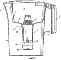
фиг.6 - продольный разрез с частичным пространственным разделением деталей фильтрующего устройства согласно второму варианту осуществления этого изобретения, при этом устройство встроено в кувшин;6 is a longitudinal section with a partial spatial separation of the parts of the filtering device according to the second embodiment of this invention, while the device is integrated in a jug;
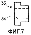
фиг.7 и 8 - соответственно виды сбоку и спереди в увеличенном масштабе части кувшина на фиг.6;Figures 7 and 8 are, respectively, side and front views on an enlarged scale of a part of the jug in Fig. 6;
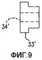
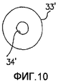
фиг.9 и 10 - виды варианта конструкции детали, сходные с видами на фиг.7 и 8;Figures 9 and 10 are views of an embodiment of a part, similar to the views of Figures 7 and 8;
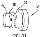
фиг.11 - вид в перспективе в увеличенном масштабе другого варианта выполнения детали на фиг.7;FIG. 11 is an enlarged perspective view of another embodiment of the component of FIG. 7;
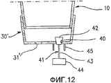
фиг.12 - схематический вид в увеличенном масштабе варианта конструкции устройства согласно изобретению;12 is a schematic enlarged view of an embodiment of a device of the invention;
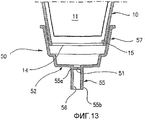
фиг.13 - схематично показанное частичное поперечное сечение в увеличенном масштабе другого варианта конструкции устройства в соответствии с изобретением;Fig - schematically shown partial cross-section on an enlarged scale of another embodiment of the design of the device in accordance with the invention;
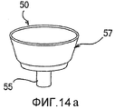
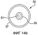
фиг.14а и 14b - соответственно виды сбоку и снизу выполнения детали на фиг.13;figa and 14b, respectively, side views and bottom views of the details of Fig.13;
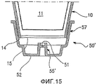
фиг.15 - схематично показанное частичное поперечное сечение в увеличенном масштабе другого варианта осуществления изобретения;FIG. 15 is a schematic enlarged partial cross-sectional view of another embodiment of the invention; FIG.
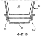
фиг.16 - схематично показанное частичное поперечное сечение в увеличенном масштабе еще одного варианта осуществления изобретения.FIG. 16 is an enlarged scale schematic view of a partial cross section of yet another embodiment of the invention. FIG.
На чертежах фильтрующее устройство согласно первому варианту осуществления изобретения в целом обозначено позицией 1. Фильтрующее устройство 1 имеет кувшинообразную форму, но изобретение могло быть подобным же образом применено к устройствам для приготовления настоев, например, чая, кофе и т.п. Устройство 1 содержит сосуд 2, который снабжен ручкой 3 и который в верхней части закрыт крышкой 4. Крышка, в свою очередь, снабжена подпружиненной створкой 5, которая с возможностью открывания автоматически закрывает выливное отверстие 6 во время выливания.In the drawings, the filter device according to the first embodiment of the invention is generally indicated by 1. The
Внутри сосуда 2 установлена емкость 7, прикрепленная к его горловине и ограничивающая первый резервуар 8 для помещения фильтруемой воды, при этом в дне 9 емкости открывается выпускной стакан 10. В стакане 10 с возможностью съема установлен фильтровальный патрон 11. Остальная часть сосуда 2 ограничивает второй резервуар 12 для сбора фильтрованной воды. Вышеописанные элементы расположены таким образом, что вода, введенная в первый резервуар 8, самотеком течет во второй резервуар 12, проходя посредством стакана 10 через фильтрующий материал, который содержится в фильтровальном патроне 11.A container 7 is installed inside the
Все вышеописанные элементы присутствуют в каждом из вариантов осуществления настоящего изобретения и, следовательно, обозначены одинаковыми позициями.All of the above elements are present in each of the embodiments of the present invention and, therefore, are denoted by the same positions.
В варианте осуществления изобретения, показанном на фиг.1 и 2, стакан 10 имеет наружную стенку 13, слегка сужающуюся по направлению к основанию 14. В наружной стенке 13 и основании 14 образовано выпускное отверстие 15, которое служит как для выпуска фильтрованной воды, так и для облегчения доступа к патрону 11, помещенному в стакане 10, для облегчения его удаления после использования, а также очистки стакана 10 по его всей протяженности.In the embodiment of the invention shown in FIGS. 1 and 2, the
Чашеобразная часть 20, имеющая закрытое основание 21 и наружную стенку 22, установлена снаружи стакана 10 в области расположения отверстия 15 так, чтобы составлять его частичное закрывающее средство, как это будет подробнее объяснено ниже. Чашеобразная часть 20 и отверстие 15 имеют такое взаимное расположение, что фильтрованная вода, выпускаемая из патрона или из нижней части выпускного отверстия 15, должна подниматься в чашеобразной части 20 и переливаться из нее во второй резервуар 12 через выпускное отверстие 22а, которое ограничено между наружной стенкой 22 и стаканом 10. Следовательно, чашеобразная часть 20 представляет собой регулятор потока для воды, вытекающей из первого резервуара во второй резервуар, для сведения к минимуму изменения в противодавлении выпускаемой из патрона воды, происходящее под влиянием изменения в уровне воды во втором резервуаре. Этот результат достигается благодаря образованию между чашеобразной частью 20 и стаканом 10 восходящего пути для воды, выпускаемой из патрона 11 и направляемой к выпускному отверстию таким образом, что выпускное отверстие 22а находится вблизи первого резервуара относительно места выпуска воды из патрона, и это определяет, что противодавление на выходе из патрона по существу не зависит от уровня воды во втором резервуаре.The cup-
Чашеобразная часть с возможностью съема прикреплена к наружной поверхности стакана 10 для осуществления очистки и облегчения удаления патрона после использования его фильтрующей способности. Предусматриваются различные средства крепления с возможностью съема: первым примером является соединение посредством незначительного натяга между нижней частью 23 наружной стенки 22 и соединенной с ней, соответствующей наружной частью стакана 10. С другой стороны, используется соединение типа защелки (см. фиг.5а) с зубьями 24а на одной из соединительных поверхностей и соответствующими выступами 24b на соответствующей другой поверхности. При другой альтернативе (см. фиг.5b) соединительные поверхности имеют соответствующие наружную и внутреннюю резьбы 24 с для образования регулируемого резьбового соединения.The cup-shaped part is removably attached to the outer surface of the
Еще с точки зрения регулирования потока предусматривается также, что наружная поверхность чашеобразной части 20 снабжена одним или несколькими резьбовыми соединениями, которые в состоянии телескопически перемещаться по наружной стенке 22 для расширения пределов ее движения вверх.From the point of view of flow control, it is also envisaged that the outer surface of the cup-
Наружная часть 23 снабжена множеством простирающихся по оси выемок 25, которые выдаются внутрь с образованием каналов для прохождения фильтрованной воды. Для этого в области основания 21 чашеобразной части образованы ребра 26, которые выступают радиально внутрь и которые ограничивают пригонку чашеобразной части к стакану 10.The
Далее излагается принцип действия фильтрующего устройства 1. Вода, вводимая в первый резервуар 8, самотеком течет ко второму резервуару 12 через фильтрующий материал патрона 11. Давление воды на входе в патрон 11 изменяется в соответствии с уровнем воды в первом резервуаре. Однако после заполнения стакана 10 и чашеобразной части давление на выходе из патрона остается постоянным во время операции фильтрования. Изменяя положение чашеобразной части 20 вдоль стакана 10, можно при желании регулировать это давление.The following describes the principle of operation of the
При втором варианте осуществления изобретения стакан 10 открыт у основания 14 и закрывается съемной крышкой 30, а выпускное отверстие выполнено в виде отверстия 31 в наружной стенке стакана 10, отдаленного по направлению оси от крышки 30 и находящегося вблизи первого резервуара 8. В этом случае путь восходящего движения воды, выпускаемой из патрона и направляемой к выпускному отверстию, образован между стаканом 10 и патроном 11, так что этот путь находится внутри стакана 10. В этом случае также предусмотрен регулятор потока, который представляет собой средство для регулируемого закрывания выпускного отверстия. В вариантах на фиг.6-10 эти закрывающие средства представляют собой средства регулирования поперечного сечения выпускного отверстия и выполнены в виде одной или нескольких пробок 33, 33', которые заменяемым образом попеременно вставляют в отверстие 31 и которые имеют калиброванные отверстия 34, 34' разного диаметра. В этом случае выпускное отверстие определяется и регулируется вышеописанными калиброванными отверстиями.In the second embodiment, the
В случае, показанном на фиг.11, средство для регулирования поперечного сечения выпускного отверстия выполнено в виде затвора 35, который имеет регулируемое поперечное сечение и который вставляют в отверстие 31. В этом случае затвор 35 содержит втулку 36, которая, в свою очередь, вставляется в отверстие 31 и снабжена внутренней резьбой и в которую ввинчивается пробка 37, при этом пробку 37, следовательно, можно постепенно вводить регулируемым образом. В пробке 37 выполнен канал 38, образующий регулируемое выпускное отверстие. Изменяя степень ввинчивания пробки 37 во втулку 35, можно, следовательно, изменять выпускное отверстие. В обоих случаях стакан 10 вместо съемной крышки 30 может быть закрыт снизу по существу сплошной стенкой 14.In the case shown in FIG. 11, the means for adjusting the cross section of the outlet is made in the form of a
В другом варианте осуществления изобретения, схематически показанном на фиг.12, закрывающее средство содержит, по меньшей мере, одно вспомогательное выпускное отверстие 40 и средство 41 для перекрытия этого отверстия. В этом случае вспомогательное отверстие расположено внизу стакана 10, который закрыт или съемной крышкой 30' (фиг.12), как в предшествующих вариантах осуществления изобретения, или нижней стенкой самого стакана. Отверстие 31, которое образует главное выпускное отверстие, может быть также выполнено в этой стенке или это отверстие может быть выполнено в любом месте.In another embodiment of the invention, schematically shown in FIG. 12, the closure means comprises at least one
Средство 41 для перекрытия вспомогательного отверстия предпочтительно является средством уровнемерного типа, которое обычно закрыто и способно открывать отверстие 40 с увеличением уровня воды во втором резервуаре. Примером такого средства является клапан 42, который стержнем 43 соединен с поплавком 44. Вокруг отверстия 40 расположены один или несколько ограничителей 45, чтобы поплавок 44 при его подъеме к патрону 11 не перекрывал вспомогательное отверстие 40. Следует отметить, что, изменяя длину стержня 43, можно изменять величину вспомогательного отверстия 40 по отношению к уровню жидкости, присутствующей во втором резервуаре 12.The means 41 for closing the auxiliary opening is preferably a level measuring device which is usually closed and capable of opening the
Таким образом, изобретение решает указанную техническую проблему с получением ряда преимуществ. Во-первых, достигается решающая стабилизация расхода по отношению к изменениям в степени наполнения обоих резервуаров. Кроме того, можно выдавливать патрон из стакана нажатием снизу, что допускает форму патрона, не определяемую с этой точки зрения. В-третьих, стакан можно легко очищать по всей протяженности стакана, что полезно в отношении гигиены фильтрующего устройства. Кроме того, можно регулировать поток воды во время фильтрования для обеспечения оптимальных результатов при этой операции.Thus, the invention solves this technical problem with a number of advantages. Firstly, a decisive stabilization of the flow rate is achieved in relation to changes in the degree of filling of both tanks. In addition, you can squeeze the cartridge out of the glass by pressing from the bottom, which allows the shape of the cartridge, not defined from this point of view. Thirdly, the glass can be easily cleaned over the entire length of the glass, which is useful in relation to the hygiene of the filter device. In addition, you can adjust the flow of water during filtration to ensure optimal results during this operation.
Claims (22)
первый резервуар (8) для помещения фильтруемой воды,
второй резервуар (12) для сбора фильтрованной воды, который наполняется при падении воды из первого резервуара (8),
стакан (10), простирающийся из первого резервуара (8) во второй резервуар,
фильтровальный элемент (11) патронного типа, размещенный с возможностью съема в этом стакане (10),
выпускное отверстие (22а, 31) для фильтрованной воды, расположенное между стаканом (10) и вторым резервуаром (12), при этом
стакан (10) имеет на дистальном конце от первого резервуара (8), по меньшей мере, одно отверстие (15) для доступа к патрону, способствующее его извлечению, отличающееся тем, что оно содержит, по меньшей мере, одно частично закрывающее стакан средство, установленное с возможностью съема на стакане (10) в области отверстия (15) для доступа к патрону, причем оно содержит регулятор потока, соединенный со стаканом (10) для регулирования потока воды, протекающей от первого резервуара во второй резервуар (12) через выпускное отверстие (22а, 31).1. A filtering device (1) for filtering water and in general liquids, comprising:
the first reservoir (8) for placing filtered water,
a second reservoir (12) for collecting filtered water, which is filled when water falls from the first reservoir (8),
a glass (10) extending from the first reservoir (8) into the second reservoir,
a filter element (11) of a cartridge type, placed with the possibility of removal in this glass (10),
an outlet (22a, 31) for filtered water, located between the glass (10) and the second tank (12), while
the glass (10) has at the distal end from the first reservoir (8) at least one opening (15) for accessing the cartridge, facilitating its extraction, characterized in that it contains at least one partially covering the glass means, installed with the possibility of removal on the glass (10) in the region of the hole (15) for access to the cartridge, and it contains a flow regulator connected to the glass (10) to regulate the flow of water flowing from the first reservoir to the second reservoir (12) through the outlet (22a, 31).
Applications Claiming Priority (4)
| Application Number | Priority Date | Filing Date | Title |
|---|---|---|---|
| ITPD2005A000153 | 2005-05-25 | ||
| ITPD20050153 ITPD20050153A1 (en) | 2005-05-25 | 2005-05-25 | FILTERING DEVICE FOR WATER AND LIQUID FILTRATION IN GENERAL |
| EP05028302.7 | 2005-12-23 | ||
| EP05028302 | 2005-12-23 |
Publications (2)
| Publication Number | Publication Date |
|---|---|
| RU2007143559A RU2007143559A (en) | 2009-05-27 |
| RU2394626C2 true RU2394626C2 (en) | 2010-07-20 |
Family
ID=37025158
Family Applications (1)
| Application Number | Title | Priority Date | Filing Date |
|---|---|---|---|
| RU2007143559/15A RU2394626C2 (en) | 2005-05-25 | 2006-05-25 | Filtration device to filter water and other fluids |
Country Status (9)
| Country | Link |
|---|---|
| US (2) | US7722761B2 (en) |
| EP (1) | EP1883607A2 (en) |
| JP (1) | JP2008542005A (en) |
| CN (1) | CN101184698B (en) |
| AU (1) | AU2006250743B2 (en) |
| CA (1) | CA2607734A1 (en) |
| IL (1) | IL187096A0 (en) |
| RU (1) | RU2394626C2 (en) |
| WO (1) | WO2006126237A2 (en) |
Families Citing this family (12)
| Publication number | Priority date | Publication date | Assignee | Title |
|---|---|---|---|---|
| RU2394626C2 (en) * | 2005-05-25 | 2010-07-20 | Лайка С.П.А. | Filtration device to filter water and other fluids |
| US8101076B2 (en) * | 2005-12-23 | 2012-01-24 | Laica S.P.A | Filter cartridge for jugs |
| ITPD20070216A1 (en) * | 2007-06-26 | 2008-12-27 | Laica Spa | FILTERING CARTRIDGE, IN PARTICULAR FOR FILTERING PASTRIES AND PERCOLATION METHOD FOR ITS MANUFACTURING |
| DE202007019085U1 (en) * | 2007-07-31 | 2010-07-01 | Selwyn Corporate Ltd., Road Town | Perkolationsfiltersystem |
| US8480882B2 (en) * | 2010-06-01 | 2013-07-09 | Protect Plus Llc | Water filter pitcher meter |
| CN103068460B (en) * | 2010-08-06 | 2015-09-09 | 贝科技术有限公司 | Cartridge oil separator |
| US20150060495A1 (en) * | 2013-09-05 | 2015-03-05 | Lincoln-Remi Group, LLC | Water Pitcher Having a Filter |
| AU201611332S (en) * | 2015-09-22 | 2016-04-26 | Brita Gmbh | Filter for water jug |
| US11713255B2 (en) | 2017-11-02 | 2023-08-01 | Aqua Chira International Incorporated | Water filter cartridge |
| US11053137B1 (en) | 2017-11-02 | 2021-07-06 | Aqua Clara International Incorporated | Water filter cartridge |
| US11872506B2 (en) * | 2018-07-07 | 2024-01-16 | Paragon Water Systems, Inc. | Water filter cartridge having an air vent |
| CN113209682A (en) * | 2021-04-22 | 2021-08-06 | 唐友慧 | Sewage treatment plant convenient for dredging urban pipeline |
Family Cites Families (10)
| Publication number | Priority date | Publication date | Assignee | Title |
|---|---|---|---|---|
| US590293A (en) * | 1897-09-21 | Gravity-filter | ||
| JPH0230071Y2 (en) * | 1984-11-01 | 1990-08-13 | ||
| DE3668880D1 (en) * | 1986-02-24 | 1990-03-15 | Leifheit Ag | DEVICE FOR FILTERING WATER. |
| GB2197647B (en) * | 1986-08-12 | 1990-03-07 | Precision Engineering Co | Improvements in or relating to water treatment devices |
| GB8815452D0 (en) * | 1988-06-29 | 1988-08-03 | Addis Ltd | Filter cartridges & filter assemblies |
| JP3856469B2 (en) * | 1994-10-28 | 2006-12-13 | ライカ・エス・ピー・エー | Container for filtering liquids, especially drinking water |
| US5882507A (en) * | 1996-04-30 | 1999-03-16 | Recovery Engineering, Inc. | Water filter cartridge end-of-life mechanism |
| GB9621637D0 (en) * | 1996-10-17 | 1996-12-11 | Robinson Thomas | A water treatment cartridge |
| US6093237A (en) * | 1998-06-04 | 2000-07-25 | Donaldson Company, Inc. | Stack filter assembly and methods |
| RU2394626C2 (en) * | 2005-05-25 | 2010-07-20 | Лайка С.П.А. | Filtration device to filter water and other fluids |
-
2006
- 2006-05-25 RU RU2007143559/15A patent/RU2394626C2/en not_active IP Right Cessation
- 2006-05-25 JP JP2008513015A patent/JP2008542005A/en active Pending
- 2006-05-25 CN CN200680018254XA patent/CN101184698B/en not_active Expired - Fee Related
- 2006-05-25 CA CA002607734A patent/CA2607734A1/en not_active Abandoned
- 2006-05-25 EP EP06756299A patent/EP1883607A2/en not_active Withdrawn
- 2006-05-25 AU AU2006250743A patent/AU2006250743B2/en not_active Ceased
- 2006-05-25 WO PCT/IT2006/000393 patent/WO2006126237A2/en not_active Application Discontinuation
-
2007
- 2007-11-01 IL IL187096A patent/IL187096A0/en unknown
- 2007-11-08 US US11/983,331 patent/US7722761B2/en not_active Expired - Fee Related
-
2010
- 2010-03-25 US US12/731,697 patent/US8298408B2/en active Active
Also Published As
| Publication number | Publication date |
|---|---|
| US20100200478A1 (en) | 2010-08-12 |
| CN101184698B (en) | 2012-08-22 |
| IL187096A0 (en) | 2008-02-09 |
| AU2006250743B2 (en) | 2010-08-19 |
| US20080073255A1 (en) | 2008-03-27 |
| CA2607734A1 (en) | 2006-11-30 |
| AU2006250743A1 (en) | 2006-11-30 |
| WO2006126237A2 (en) | 2006-11-30 |
| JP2008542005A (en) | 2008-11-27 |
| CN101184698A (en) | 2008-05-21 |
| RU2007143559A (en) | 2009-05-27 |
| EP1883607A2 (en) | 2008-02-06 |
| US7722761B2 (en) | 2010-05-25 |
| WO2006126237A3 (en) | 2007-01-18 |
| US8298408B2 (en) | 2012-10-30 |
Similar Documents
| Publication | Publication Date | Title |
|---|---|---|
| RU2394626C2 (en) | Filtration device to filter water and other fluids | |
| US5860354A (en) | Infusion machine including a water purification device | |
| US6279460B1 (en) | Tea brewing funnel | |
| EP2251305B1 (en) | Filter cartridge for jugs | |
| US20060249442A1 (en) | Water filtration system with improved performance | |
| JP2008542005A5 (en) | ||
| WO2009094549A2 (en) | Filter device | |
| EP2148839A1 (en) | Water treatment cartridges | |
| AU2012251480B2 (en) | Water treatment apparatus | |
| UA97472C2 (en) | Filtering cartridge for jugs | |
| KR200478513Y1 (en) | Dutch coffee extracting device | |
| KR101668580B1 (en) | Dutch coffee maker | |
| KR19990058602A (en) | Coffee Maker | |
| WO2006079344A1 (en) | Drip-proof pouring insert | |
| KR101701251B1 (en) | Dutch coffee maker | |
| JP2007075434A (en) | Dripper | |
| JPH0499532A (en) | Jar pot |
Legal Events
| Date | Code | Title | Description |
|---|---|---|---|
| MM4A | The patent is invalid due to non-payment of fees |
Effective date: 20120526 |