RU2384373C1 - Ultrasonic oscillating system - Google Patents
Ultrasonic oscillating system Download PDFInfo
- Publication number
- RU2384373C1 RU2384373C1 RU2008137336/28A RU2008137336A RU2384373C1 RU 2384373 C1 RU2384373 C1 RU 2384373C1 RU 2008137336/28 A RU2008137336/28 A RU 2008137336/28A RU 2008137336 A RU2008137336 A RU 2008137336A RU 2384373 C1 RU2384373 C1 RU 2384373C1
- Authority
- RU
- Russia
- Prior art keywords
- transformer
- titanium alloy
- amplitude
- cavity
- oscillation
- Prior art date
Links
- 230000010355 oscillation Effects 0.000 claims abstract description 26
- 229910001069 Ti alloy Inorganic materials 0.000 claims abstract description 21
- 239000000463 material Substances 0.000 claims abstract description 15
- 230000003534 oscillatory effect Effects 0.000 claims description 16
- 239000007788 liquid Substances 0.000 abstract description 7
- 238000000034 method Methods 0.000 abstract description 5
- 230000008569 process Effects 0.000 abstract description 5
- 230000000694 effects Effects 0.000 abstract description 2
- 238000012545 processing Methods 0.000 abstract description 2
- 239000013081 microcrystal Substances 0.000 abstract 2
- 230000003247 decreasing effect Effects 0.000 abstract 1
- 239000012530 fluid Substances 0.000 abstract 1
- 239000000126 substance Substances 0.000 abstract 1
- 229910045601 alloy Inorganic materials 0.000 description 7
- 239000000956 alloy Substances 0.000 description 7
- 238000013461 design Methods 0.000 description 5
- 230000008859 change Effects 0.000 description 3
- 230000007423 decrease Effects 0.000 description 3
- 229910000831 Steel Inorganic materials 0.000 description 2
- RTAQQCXQSZGOHL-UHFFFAOYSA-N Titanium Chemical compound [Ti] RTAQQCXQSZGOHL-UHFFFAOYSA-N 0.000 description 2
- 238000011161 development Methods 0.000 description 2
- 238000006073 displacement reaction Methods 0.000 description 2
- 238000005516 engineering process Methods 0.000 description 2
- 238000010438 heat treatment Methods 0.000 description 2
- 238000011089 mechanical engineering Methods 0.000 description 2
- 239000002609 medium Substances 0.000 description 2
- 230000005855 radiation Effects 0.000 description 2
- 239000010959 steel Substances 0.000 description 2
- 239000010936 titanium Substances 0.000 description 2
- 229910052719 titanium Inorganic materials 0.000 description 2
- 230000007704 transition Effects 0.000 description 2
- 239000012736 aqueous medium Substances 0.000 description 1
- 125000004122 cyclic group Chemical group 0.000 description 1
- 238000010586 diagram Methods 0.000 description 1
- 239000012634 fragment Substances 0.000 description 1
- 230000004927 fusion Effects 0.000 description 1
- 230000006872 improvement Effects 0.000 description 1
- 238000009434 installation Methods 0.000 description 1
- 238000005259 measurement Methods 0.000 description 1
- 229910052751 metal Inorganic materials 0.000 description 1
- 239000002184 metal Substances 0.000 description 1
- 150000002739 metals Chemical class 0.000 description 1
- 229910052759 nickel Inorganic materials 0.000 description 1
- PXHVJJICTQNCMI-UHFFFAOYSA-N nickel Substances [Ni] PXHVJJICTQNCMI-UHFFFAOYSA-N 0.000 description 1
- 230000010363 phase shift Effects 0.000 description 1
- 230000035945 sensitivity Effects 0.000 description 1
- XLYOFNOQVPJJNP-UHFFFAOYSA-N water Substances O XLYOFNOQVPJJNP-UHFFFAOYSA-N 0.000 description 1
- 238000003466 welding Methods 0.000 description 1
- 238000004804 winding Methods 0.000 description 1
Images

Landscapes
- Apparatuses For Generation Of Mechanical Vibrations (AREA)
Abstract
Description
Изобретение относится к ультразвуковой технике, а именно к колебательным системам, и может быть использовано как при разработке акустических систем различного технологического назначения, так и в существующем ультразвуковом оборудовании, созданном на базе преобразователей разных типов.The invention relates to ultrasonic technology, namely to oscillatory systems, and can be used both in the development of acoustic systems for various technological purposes, and in existing ultrasonic equipment created on the basis of transducers of various types.
Известный ультразвуковой преобразователь (RU 41648, В06В 1/00, опубл. 2004.11.10)[1] содержит волновод в виде цилиндра длиной, равной λ/2, который соединен с трансформатором продольных колебаний; трансформатор поперечных колебаний; в виде четырехугольной призмы, на основаниях которой установлен рабочий орган, две боковые поверхности соединены с волноводом, а через центры двух других боковых поверхностей выполнено отверстие, ось которого перпендикулярна оси волновода и находится на расстоянии λ/8 от торца волновода, при этом длина призмы равна λ/7, λ - длина волны в материале волновода.Known ultrasonic transducer (RU 41648,
Недостатком известного ультразвукового преобразователя является недостаточно высокая удельная акустическая мощность. Также к недостаткам известного ультразвукового преобразователя можно отнести невысокую амплитуду колебаний рабочего органа и недостаточный ресурс работы.A disadvantage of the known ultrasonic transducer is not sufficiently high specific acoustic power. Also, the disadvantages of the known ultrasonic transducer include the low amplitude of the vibrations of the working body and the insufficient resource of work.
Наиболее близким аналогом является устройство для ультразвуковых технологических комплектов (RU 41649, В06В 3/00, опубл. 10.11.2004) [2], который содержит ступенчатый концентратор продольных колебаний, выполненный из титанового сплава, соединенный с ним активный элемент в виде набора О-образных пластин из магнитострикционного сплава, имеет на торце стяжки из титанового сплава, кроме того, ступенчатый концентратор продольных колебаний соединен с активным элементом посредством сварки оплавления.The closest analogue is a device for ultrasonic technological kits (RU 41649,
Это известное устройство для ультразвуковых технологических комплектов также обладает невысокой удельной акустической мощностью. Недостатками известного устройства для ультразвуковых технологических комплектов также являются невысокая амплитуда колебаний ступенчатого концентратора продольных колебаний, недостаточный ресурс работы.This known device for ultrasonic technology kits also has a low specific acoustic power. The disadvantages of the known device for ultrasonic technological kits are also a low amplitude of the oscillations of the stepwise concentrator of longitudinal vibrations, insufficient life.
Задачей предлагаемого изобретения является разработка ультразвуковой колебательной системы технологического назначения с повышенным КПД и высокой удельной акустической мощностью. При использовании этой системы для обработки жидких сред происходит улучшение кавитационной способности жидкости.The task of the invention is the development of an ultrasonic oscillatory system for technological purposes with increased efficiency and high specific acoustic power. When using this system for processing liquid media, the cavitation ability of the liquid is improved.
Указанный технический результат достигается тем, что ультразвуковая колебательная система технологического назначения включает преобразователь, трансформатор колебаний и излучающий инструмент.The specified technical result is achieved in that the ultrasonic oscillatory system for technological purposes includes a transducer, an oscillation transformer and a radiating tool.
Новым является то, что она содержит, по крайней мере, два трансформатора, усиливающие упругие колебания и имеющие длину, кратную λ/2, где λ - длина продольной волны в материале волновода, причем, по крайней мере, трансформатор второй ступени изготовлен из титанового сплава с субмикрокристаллической структурой и выполнен в виде ступенчатого вдоль продольной оси цилиндрического стержня с полостью, расположенной соосно стержню и уменьшающей площадь его выходного сечения, и излучающий инструмент, выполненный из титанового сплава с субмикрокристаллической структурой.What is new is that it contains at least two transformers that amplify elastic vibrations and have a length that is a multiple of λ / 2, where λ is the longitudinal wavelength in the waveguide material, and at least the second-stage transformer is made of a titanium alloy with a submicrocrystalline structure and made in the form of a cylindrical rod stepwise along the longitudinal axis with a cavity located coaxially with the rod and reducing its output section area, and a radiating tool made of a titanium alloy with submicrocirc and isalic structure.
Колебательная система содержит преобразователь либо магнитострикционный, либо пьезокерамический.The oscillation system contains either a magnetostrictive or piezoceramic transducer.
В колебательной системе трансформаторы колебаний и излучающий инструмент соединены между собой посредством шпильки, выполненной из титанового сплава с субмикрокристаллической структурой.In an oscillatory system, oscillation transformers and a radiating tool are interconnected by means of a pin made of a titanium alloy with a submicrocrystalline structure.
В колебательной системе в качестве титанового сплава с субмикрокристаллической структурой используют титан марки ПТ-3В.In the oscillatory system, titanium of the PT-3V grade is used as a titanium alloy with a submicrocrystalline structure.
В колебательной системе длина второй ступени и длина полости трансформатора должны быть одинаковыми и кратными λ/4.In an oscillatory system, the length of the second stage and the length of the cavity of the transformer must be the same and a multiple of λ / 4.
В колебательной системе радиус полости трансформатора не превышает значения 0.7 от величины радиуса выходного сечения трансформатора.In an oscillatory system, the radius of the transformer cavity does not exceed a value of 0.7 of the radius of the output section of the transformer.
В колебательной системе полость трансформатора имеет с внутреннего конца сферическую форму с чистотой обработки поверхности полости Ra не более 1.25 мкм.In the oscillatory system, the transformer cavity has a spherical shape from the inner end with a surface finish Ra of no more than 1.25 μm.
Для обоснования предполагаемых технических результатов по повышению КПД и высокой удельной мощности рассмотрим основные акустические параметры ультразвуковой колебательной системы технологического назначения, которые обеспечивают заданные характеристики технологического процесса - это частота, амплитуда колебаний (удельная акустическая мощность), площадь рабочей поверхности излучающего инструмента.To substantiate the alleged technical results in increasing efficiency and high specific power, we consider the main acoustic parameters of an ultrasonic oscillatory system for technological purposes that provide the specified characteristics of the process - this is the frequency, amplitude of oscillations (specific acoustic power), and the area of the working surface of the radiating instrument.
Для процессов, связанных с кавитационной активностью жидкости, и для интенсификации технологических процессов в жидких средах известно оптимальное значение удельной акустической мощности, например для водных сред составляет ωa=1,5…2,0 Вт/см2. Этому значению удельной акустической мощности соответствует амплитуда колебательной скорости на поверхности излучателя 0,2 м/с [4].For processes associated with cavitational activity of a liquid, and for the intensification of technological processes in liquid media, the optimal value of specific acoustic power is known, for example, for aqueous media it is ω a = 1.5 ... 2.0 W / cm 2 . This value of specific acoustic power corresponds to the amplitude of the vibrational velocity on the surface of the emitter 0.2 m / s [4].
Условия работы при излучении в среду характеризуются заданной площадью излучения и удельной акустической мощностью, которая определяется для заданного технологического процесса. Заданному значению удельной акустической мощности соответствует определенная амплитуда колебательных смещений.The operating conditions for radiation into the medium are characterized by a given radiation area and specific acoustic power, which is determined for a given process. The specified value of the specific acoustic power corresponds to a certain amplitude of vibrational displacements.
Сопротивлением нагрузки называют отношение мгновенных значений силы и скорости. При гармонических колебаниях с учетом сдвига фаз это отношение имеет активную и реактивную компоненты:The resistance of the load is the ratio of the instantaneous values of force and speed. With harmonic oscillations, taking into account the phase shift, this ratio has an active and reactive components:
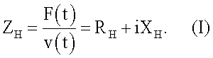
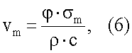
Реактивная составляющая Хн приводит к изменению частоты резонанса, активная составляющая RH связана со снижением амплитуды колебательной скорости. В линейном приближении, т.е. в случае, когда сила F(t) и скорость v(t) изменятся по гармоническому закону и амплитуда силы пропорциональна амплитуде колебательной скорости, акустическая мощность, излучаемая в нагрузку, пропорциональна произведению активной составляющей сопротивления нагрузки на квадрат амплитуды колебательной скорости:The reactive component X n leads to a change in the resonance frequency, the active component R H is associated with a decrease in the amplitude of the vibrational velocity. In the linear approximation, i.e. in the case when the force F (t) and speed v (t) change in harmonic law and the amplitude of the force is proportional to the amplitude of the vibrational velocity, the acoustic power radiated into the load is proportional to the product of the active component of the load resistance by the square of the amplitude of the vibrational velocity:
![]()
![]()
где vm - амплитуда колебательной скорости.where v m is the amplitude of the vibrational velocity.
Как известно, при малой амплитуде колебаний реактивная составляющая при излучении в воду представляет собой присоединенную массу. С увеличением амплитуды до 1-3 мкм реактивная составляющая уменьшается до нуля. Установлено, что акустическая мощность, излучаемая в жидкость, растет с увеличением амплитуды колебательной скорости. Полная акустическая мощностьAs is known, with a small amplitude of oscillations, the reactive component when emitted into water is an attached mass. With an increase in amplitude to 1-3 μm, the reactive component decreases to zero. It has been established that the acoustic power radiated into a liquid increases with an increase in the amplitude of the vibrational velocity. Total acoustic power
![]()
![]()
где S - площадь излучающей поверхности;where S is the area of the radiating surface;
ωa(ξmн) - удельная акустическая мощность, излучаемая в жидкую технологическую среду.ω a (ξ mн ) is the specific acoustic power radiated into the liquid technological medium.
Амплитуда колебаний при заданной величине напряжения на входе преобразователя:The amplitude of the oscillations at a given voltage at the input of the Converter:
![]()
![]()
где A - значение определяется выбором конструкции преобразователя;where A is the value determined by the choice of the design of the Converter;
g=l-1 для пьезокерамического преобразователя;g = l -1 for the piezoceramic transducer;
g=(2πfNS2)2 для магнитострикционного преобразователя,g = (2πfNS 2 ) 2 for the magnetostrictive transducer,
где f - частота; N - количество витков обмотки возбуждения; S2 - площадь поперечного сечения магнитопровода; Um - напряжение на входе преобразователя; RМ.П - сопротивление механических потерь преобразователя; RH - сопротивление нагрузки; l - толщина пьезоэлемента.where f is the frequency; N is the number of turns of the field winding; S 2 - the cross-sectional area of the magnetic circuit; U m is the voltage at the input of the Converter; R M.P - resistance to mechanical losses of the Converter; R H - load resistance; l is the thickness of the piezoelectric element.
При малых уровнях амплитуды входного напряжения чувствительность преобразователя можно считать величиной постоянной, что соответствует линейной зависимости амплитуды колебаний от амплитуды напряжения на входе. Однако существует предел увеличения амплитуды колебаний для данной конструкции ультразвукового преобразователя. Предельная амплитуда ξmax является основным параметром, характеризующим работу преобразователя при больших уровнях входной мощности. В зависимости от типа преобразователя, выбранного материала и характера нагрузки ограничивающими факторами могут быть: усталостная прочность, нелинейность магнитных и магнитострикционных характеристик, степень допустимого нагрева преобразователя.At low levels of the amplitude of the input voltage, the sensitivity of the converter can be considered constant, which corresponds to a linear dependence of the amplitude of the oscillations on the amplitude of the input voltage. However, there is a limit to the increase in the amplitude of oscillations for a given design of the ultrasonic transducer. The limiting amplitude ξ max is the main parameter characterizing the operation of the converter at high input power levels. Depending on the type of converter, the selected material and the nature of the load, the limiting factors can be: fatigue strength, nonlinearity of magnetic and magnetostrictive characteristics, the degree of permissible heating of the converter.
Для магнитострикционных преобразователей технологического назначения предельная амплитуда, наряду с усталостной прочностью элементов конструкции (волноводы и инструмент), ограничивается магнитным насыщением.For magnetostrictive converters for technological purposes, the limiting amplitude, along with the fatigue strength of structural elements (waveguides and tools), is limited by magnetic saturation.
Пример расчета [4] максимальной амплитуды колебательных смещений магнитострикционного преобразователя, набранного из пластин ПП-40 сплава 49КФ. Частота f=22 кГц; l1=13 мм; q=1,54; γH=0,1; Q=140 (см. табл.2).Calculation example [4] of the maximum amplitude of vibrational displacements of a magnetostrictive transducer recruited from PP-40 plates of 49KF alloy. Frequency f = 22 kHz; l 1 = 13 mm; q = 1.54; γ H = 0.1; Q = 140 (see table 2).
По формулеAccording to the formula
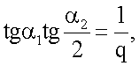
где ![]()
![]()
![]()
![]()
найдем α1=2,129 и, подставляя значения параметров в формулу (5), получаемwe find α 1 = 2,129 and, substituting the parameter values in the formula (5), we obtain
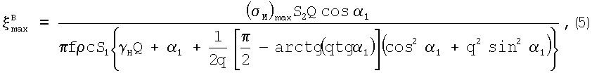
![]()
![]()
Таким образом, расчет показывает, что на магнитострикционном пакете можно получить, в зависимости от его конструкции и применяемого материала, максимальную амплитуду не выше 3-5 мкм. Измерения магнитострикционных пакетов на частоту 22 кГц с набором пластин 24×24; 35×35; 35×60 подтверждают расчетную величину амплитуды. Поэтому для повышения амплитуды инструмента, его удельной акустической мощности необходимо применять трансформаторы упругих колебаний, например, в виде ступенчатых волноводов.Thus, the calculation shows that, on a magnetostrictive bag, it is possible to obtain, depending on its design and the material used, a maximum amplitude of no higher than 3-5 microns. Measurement of magnetostrictive packets at a frequency of 22 kHz with a set of plates 24 × 24; 35 × 35; 35 × 60 confirm the calculated magnitude of the amplitude. Therefore, to increase the amplitude of the instrument, its specific acoustic power, it is necessary to use transformers of elastic vibrations, for example, in the form of stepwise waveguides.
Одним из основных факторов, ограничивающих допустимую амплитуду колебаний или допустимую мощность волноводов, является усталостная прочность материала. Допустимая амплитуда колебаний определяется надежностью ультразвуковых преобразователей и волноводов, которая характеризуется длительностью непрерывной работы преобразователя в заданном режиме до момента его усталостного разрушения. Известно, что одновременно с ростом амплитуды колебаний пропорционально увеличивается амплитуда напряжений в пучности деформаций. Введенный Эйснером фактор формы φ позволил связать амплитуду колебательной скорости на конце волновода vm с амплитудой напряжений в пучности деформаций σm через волновое сопротивление материала ρc:One of the main factors limiting the allowable vibration amplitude or allowable waveguide power is the fatigue strength of the material. The permissible vibration amplitude is determined by the reliability of the ultrasonic transducers and waveguides, which is characterized by the duration of the continuous operation of the transducer in a given mode until its fatigue failure. It is known that, simultaneously with an increase in the amplitude of oscillations, the amplitude of stresses in the antinode of strains increases proportionally. The form factor φ introduced by Eisner allowed us to relate the amplitude of the vibrational velocity at the end of the waveguide v m with the stress amplitude in the antinode of strains σ m through the wave resistance of the material ρc:
где ρ - плотность материала волновода, с - скорость звука в материале волновода.where ρ is the density of the waveguide material, and c is the speed of sound in the waveguide material.
Величина φ, называемая фактором формы, является безразмерным параметром, зависящим только от соотношения определенных размеров. Поскольку максимальное значение σm не может быть больше значения усталостной прочности для данного материала, то, подставляя в уравнение (6) вместо σm величину усталостной прочности σmax, для данной конструкции преобразователя получимThe quantity φ, called the form factor, is a dimensionless parameter that depends only on the ratio of certain sizes. Since the maximum value of σ m cannot be greater than the value of fatigue strength for a given material, substituting in the equation (6) instead of σ m the value of fatigue strength σ max , for this converter design we obtain
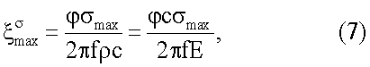
где Е - модуль Юнга; с - скорость звука.where E is Young's modulus; c is the speed of sound.
Изобретение иллюстрируется фиг.1-4.The invention is illustrated in figures 1-4.
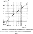
На фиг.1 приведена зависимость удельной акустической мощности от амплитуды ξmн колебаний излучающего инструмента под нагрузкой [4].Figure 1 shows the dependence of the specific acoustic power on the amplitude ξ mn of oscillations of the radiating instrument under load [4].
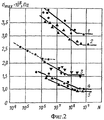
На фиг.2 приведена усталостная кривая, полученная для различных материалов [5] на частоте f=20 кГц, гдеFigure 2 shows the fatigue curve obtained for various materials [5] at a frequency f = 20 kHz, where
1 - титановый сплав ОТ4-1; 2 - сталь 45; 3 - сплав Д16Т; 4 - пермендюр 49КФ; 5 - никель Н-2. Штриховой линией изображена усталостная прочность стали 45 на частоте f=16 Гц. Найденная зависимость справедлива при постоянной температуре; при нагреве образца циклическая прочность снижается.1 - titanium alloy OT4-1; 2 - steel 45; 3 - alloy D16T; 4 - change 49KF; 5 - nickel H-2. The dashed line shows the fatigue strength of steel 45 at a frequency f = 16 Hz. The found dependence is valid at a constant temperature; when the sample is heated, the cyclic strength decreases.
Как видно из фиг.2, располагая данными по усталости материалов, можно определить допустимую амплитуду ультразвуковых напряжений при заданной длительности или определить длительность при заданной амплитуде ультразвуковых напряжений.As can be seen from figure 2, having data on the fatigue of materials, you can determine the allowable amplitude of ultrasonic stresses for a given duration or determine the duration at a given amplitude of ultrasonic stresses.
Титановые сплавы с субмикрокристаллической структурой, в частности, марки ПТ-3В имеют повышенную усталостную прочность. Характерный размер элементов (зерен, субзерен, фрагментов) титана с УМЗ структурой не должен превышать 1.0 мкм.Titanium alloys with a submicrocrystalline structure, in particular, PT-3V grades, have increased fatigue strength. The characteristic size of elements (grains, subgrains, fragments) of titanium with an UFG structure should not exceed 1.0 μm.
На фиг.3 изображена схема ультразвуковой колебательной системы, гдеFigure 3 shows a diagram of an ultrasonic oscillatory system, where
1 - магнитострикционный преобразователь; 2 - трансформатор упругих колебаний (первая ступень); 3 - трансформатор упругих колебаний (вторая ступень); 4 - излучающий инструмент, выполненный из титанового сплава с субмикрокристаллической структурой (соединительные шпильки не изображены).1 - magnetostrictive transducer; 2 - transformer of elastic vibrations (first stage); 3 - transformer of elastic vibrations (second stage); 4 - a radiating tool made of a titanium alloy with a submicrocrystalline structure (connecting studs are not shown).
На фиг.4 схематично изображен трансформатор упругих колебаний 3 (вторая ступень), выполненный из титанового сплава с субмикрокристаллической структурой в виде ступенчатого вдоль продольной оси цилиндрического стержня с полостью (5), расположенной соосно стержню, где L - расстояние между плоскостью перехода одной ступени трасформатора в другую и плоскостью внутреннего конца полости.Figure 4 schematically shows a transformer of elastic vibrations 3 (second stage) made of a titanium alloy with a submicrocrystalline structure in the form of a cylindrical rod stepwise along the longitudinal axis with a cavity (5) located coaxially with the rod, where L is the distance between the transition plane of one stage of the transformer to the other and the plane of the inner end of the cavity.
Исследования, выполненные авторами изобретения, показали, что волноводы из титанового сплава ПТ-3В с субмикрокристаллической структурой имеют существенные преимущества по основным характеристикам перед волноводами из крупнокристаллического сплава, в частности по ресурсу работы - на два порядка, по максимальной амплитуде - в несколько раз и по допустимой подводимой мощности - в 1,5-2,0 раза. Такое существенное улучшение характеристик волноводов даже при увеличении стоимости заготовок субмикрокристаллического сплава ПТ-3В в 2 раза по сравнению с крупнокристаллическим сплавом обеспечит высокую конкурентоспособность разрабатываемых волноводов.Studies performed by the inventors have shown that PT-3V titanium alloy waveguides with a submicrocrystalline structure have significant advantages in terms of basic characteristics over coarse-crystalline alloy waveguides, in particular, in operating life, by two orders of magnitude, by maximum amplitude, by several times and by permissible input power - 1.5-2.0 times. Such a significant improvement in the characteristics of waveguides, even with a 2-fold increase in the cost of preforms of the PT-3V submicrocrystalline alloy compared to a coarse-grained alloy, will ensure the high competitiveness of the developed waveguides.
Заявляемая ультразвуковая колебательная система технологического назначения, включающая преобразователь, который может быть либо магнитострикционным, либо пьезокерамическим; по крайней мере, два трансформатора скоростей и излучающий инструмент, имеет важную отличительную особенность в том, что трансформатор, по крайней мере, второй ступени с большим коэффициентом усиления изготовлен из титанового сплава с субмикрокристаллической структурой, в частности из титанового сплава ПТ-3В, превышающего механические характеристики известных высокопрочных металлов и сплавов с макроструктурой.The inventive ultrasonic oscillatory system for technological purposes, including a transducer, which can be either magnetostrictive or piezoceramic; at least two speed transformers and a radiating tool have an important distinguishing feature in that the transformer of at least the second stage with a high gain is made of a titanium alloy with a submicrocrystalline structure, in particular PT-3V titanium alloy, exceeding mechanical characteristics of well-known high-strength metals and alloys with a macrostructure.
Выполнение трансформатора второй ступени в виде ступенчатого вдоль продольной оси цилиндрического стержня с полостью, расположенной соосно стержню и уменьшающей площадь его выходного сечения, что дополнительно увеличивает коэффициент усиления колебаний.The implementation of the second stage transformer in the form of a stepped along the longitudinal axis of the cylindrical rod with a cavity located coaxially with the rod and reducing the area of its output section, which further increases the gain of the oscillations.
Соединение трансформаторов между собой и с излучающим инструментом осуществляется посредством шпилек, выполненных из титанового сплава с субмикрокристаллической структурой. Это позволяет при соединении трансформаторов и инструмента применить высокое усилие закручивания и тем самым обеспечить плотный акустический контакт с очень малыми потерями энергии на нагрев, кроме того, увеличивается ресурс работы шпилечного соединения. Трансформатор упругих колебаний первой ступени выполнен из обычного материала длиной, кратной λ/2, а излучающий инструмент выполняется из титанового сплава с субмикрокристаллической структурой, что повышает КПД, удельную мощность системы и при этом повышается ее ресурс работы.The transformers are connected to each other and to the radiating tool by means of studs made of a titanium alloy with a submicrocrystalline structure. This makes it possible to use a high twisting force when connecting transformers and a tool and thereby ensure tight acoustic contact with very low energy losses for heating, in addition, the service life of the hairpin connection increases. The elastic oscillation transformer of the first stage is made of ordinary material, a multiple of λ / 2, and the radiating tool is made of a titanium alloy with a submicrocrystalline structure, which increases the efficiency, specific power of the system and at the same time increases its service life.
В трансформаторе второй ступени расстояние между плоскостью перехода одной ступени в другую и плоскостью внутреннего конца полости должно быть кратным λ/2 и составлять не менее 1/3 длины полости трансформатора. Эти конструктивные особенности необходимы для усиления амплитуды колебаний и сохранения прочностных характеристик трансформатораIn the transformer of the second stage, the distance between the plane of transition of one stage to another and the plane of the inner end of the cavity should be a multiple of λ / 2 and be at least 1/3 of the length of the cavity of the transformer. These design features are necessary to enhance the amplitude of the oscillations and preserve the strength characteristics of the transformer
В трансформаторе второй ступени радиус полости не превышает значения 0.7 от величины радиуса выходного сечения трансформатора. Это тот допустимый предел, который позволяет оптимизировать оптимальное сочетание уменьшения площади выходного сечения трансформатора и прочности его конструкции.In the transformer of the second stage, the radius of the cavity does not exceed a value of 0.7 of the radius of the output section of the transformer. This is the allowable limit that allows you to optimize the optimal combination of reducing the output section of the transformer and the strength of its structure.
В колебательной системе полость трансформатора второй ступени имеет с внутреннего конца сферическую форму с чистотой обработки поверхности полости Ra не более 1.25 мкм. Это позволяет уменьшить концентрацию механических напряжений, возникающих на неровностях поверхности.In the oscillating system, the cavity of the transformer of the second stage has a spherical shape from the inner end with a surface finish of Ra cavity no more than 1.25 μm. This allows you to reduce the concentration of mechanical stresses arising on surface irregularities.
Ультразвуковая колебательная система работает следующим образом.Ultrasonic oscillatory system operates as follows.
В преобразователе 1 (активном элементе колебательной системы) создается знакопеременная механическая сила. Трансформаторы упругих колебаний 2, 3 осуществляют согласование механического сопротивления внешней нагрузки и внутреннего сопротивления активного элемента, а также обеспечивают нужную амплитуду колебаний. Излучатель создает ультразвуковое поле в обрабатываемом объекте или непосредственно воздействует на него. Получение при этом амплитуды колебаний не менее 100 мкм обеспечивает высокую удельную мощность системы.In the transducer 1 (the active element of the oscillatory system) creates alternating mechanical force. Transformers of
Источники информацииInformation sources
1. Патент РФ №41648, В06В 1/00, опубл. 2004.11.10.1. RF patent No. 41648,
2. Патент РФ №41649, В06В 3/00, опубл. 10.11.2004.2. RF patent No. 41649,
3. Китайгородский Ю.И., Яхимович Д.Ф. Инженерный расчет ультразвуковых колебательных систем. - М.: Машиностроение, 1982, 56 с.3. Kitaygorodsky Yu.I., Yakhimovich D.F. Engineering calculation of ultrasonic oscillatory systems. - M.: Mechanical Engineering, 1982, 56 p.
4. Казанцев В.Ф. Расчет ультразвуковых преобразователей для технологических установок. - М.: Машиностроение, 1980, 44 с.4. Kazantsev V.F. Calculation of ultrasonic transducers for technological installations. - M.: Mechanical Engineering, 1980, 44 p.
5. Усталостная прочность материалов и элементов конструкций при звуковых и ультразвуковых частотах нагружения. Киев, Наукова думка, 1977, 250 с.5. Fatigue strength of materials and structural elements at sound and ultrasonic loading frequencies. Kiev, Naukova Dumka, 1977, 250 p.
Claims (7)
Priority Applications (1)
| Application Number | Priority Date | Filing Date | Title |
|---|---|---|---|
| RU2008137336/28A RU2384373C1 (en) | 2008-09-17 | 2008-09-17 | Ultrasonic oscillating system |
Applications Claiming Priority (1)
| Application Number | Priority Date | Filing Date | Title |
|---|---|---|---|
| RU2008137336/28A RU2384373C1 (en) | 2008-09-17 | 2008-09-17 | Ultrasonic oscillating system |
Publications (1)
| Publication Number | Publication Date |
|---|---|
| RU2384373C1 true RU2384373C1 (en) | 2010-03-20 |
Family
ID=42137308
Family Applications (1)
| Application Number | Title | Priority Date | Filing Date |
|---|---|---|---|
| RU2008137336/28A RU2384373C1 (en) | 2008-09-17 | 2008-09-17 | Ultrasonic oscillating system |
Country Status (1)
| Country | Link |
|---|---|
| RU (1) | RU2384373C1 (en) |
Cited By (2)
| Publication number | Priority date | Publication date | Assignee | Title |
|---|---|---|---|---|
| RU2473400C2 (en) * | 2011-08-10 | 2013-01-27 | Общество с ограниченной ответственностью "Центр ультразвуковых технологий" | Ultrasonic vibration system |
| RU2759639C1 (en) * | 2020-11-27 | 2021-11-16 | федеральное государственное бюджетное образовательное учреждение высшего образования "Самарский государственный технический университет" | Device for mounting contact pins on printed circuit boards |
Citations (4)
| Publication number | Priority date | Publication date | Assignee | Title |
|---|---|---|---|---|
| SU633615A1 (en) * | 1977-02-14 | 1978-11-25 | Московский Ордена Ленина Авиационный Имени Имени Серго Орджоникидзе | Ultrasonic oscillation system |
| SU817809A1 (en) * | 1978-06-26 | 1981-03-30 | Специальное Проектно-Конструкторскоеи Технологическое Бюро Малых Элект-Рических Машин Производственногообъединения "Эльфа" | Rod-type ultrasonic oscillatory system |
| US5820011A (en) * | 1995-04-19 | 1998-10-13 | Ngk Spark Plug Co., Ltd. | Ultrasonic tool horn |
| RU2311971C1 (en) * | 2006-07-26 | 2007-12-10 | Никольский Константин Николаевич | Acoustic transformer |
-
2008
- 2008-09-17 RU RU2008137336/28A patent/RU2384373C1/en not_active IP Right Cessation
Patent Citations (4)
| Publication number | Priority date | Publication date | Assignee | Title |
|---|---|---|---|---|
| SU633615A1 (en) * | 1977-02-14 | 1978-11-25 | Московский Ордена Ленина Авиационный Имени Имени Серго Орджоникидзе | Ultrasonic oscillation system |
| SU817809A1 (en) * | 1978-06-26 | 1981-03-30 | Специальное Проектно-Конструкторскоеи Технологическое Бюро Малых Элект-Рических Машин Производственногообъединения "Эльфа" | Rod-type ultrasonic oscillatory system |
| US5820011A (en) * | 1995-04-19 | 1998-10-13 | Ngk Spark Plug Co., Ltd. | Ultrasonic tool horn |
| RU2311971C1 (en) * | 2006-07-26 | 2007-12-10 | Никольский Константин Николаевич | Acoustic transformer |
Cited By (2)
| Publication number | Priority date | Publication date | Assignee | Title |
|---|---|---|---|---|
| RU2473400C2 (en) * | 2011-08-10 | 2013-01-27 | Общество с ограниченной ответственностью "Центр ультразвуковых технологий" | Ultrasonic vibration system |
| RU2759639C1 (en) * | 2020-11-27 | 2021-11-16 | федеральное государственное бюджетное образовательное учреждение высшего образования "Самарский государственный технический университет" | Device for mounting contact pins on printed circuit boards |
Similar Documents
| Publication | Publication Date | Title |
|---|---|---|
| US7156201B2 (en) | Ultrasonic rod waveguide-radiator | |
| US3368085A (en) | Sonic transducer | |
| Peshkovsky et al. | Matching a transducer to water at cavitation: Acoustic horn design principles | |
| Stanzl-Tschegg et al. | High frequency method for torsion fatigue testing | |
| Pérez-Sánchez et al. | Numerical design and analysis of a langevin power ultrasonic transducer for acoustic cavitation generation | |
| CN103028540B (en) | Ultrasonic tool head | |
| Khmelev et al. | Summation of high-frequency Langevin transducers vibrations for increasing of ultrasonic radiator power | |
| Neppiras | Very high energy ultrasonics | |
| Kudryavtsev et al. | Fatigue life improvement of welded elements by ultrasonic peening | |
| WO2021208283A1 (en) | Ultrasonic vibration platform for processing large part, and operating process therefor | |
| Khmelev et al. | Ultrasonic transducer with increased exposure power and frequency up to 100 kHz | |
| RU2384373C1 (en) | Ultrasonic oscillating system | |
| RU2332266C1 (en) | Ultrasonic vibration system | |
| Shu et al. | On the design and analysis of acoustic horns for ultrasonic welding | |
| Kudryavtsev et al. | Increasing fatigue strength of welded joints by ultrasonic impact treatment | |
| RU2141386C1 (en) | Ultrasonic oscillation system | |
| RU2672530C1 (en) | Ultrasonic oscillating system (variants) | |
| RU94488U1 (en) | ULTRASONIC VIBRATION SYSTEM | |
| RU2548344C2 (en) | Device for ultrasonic processing | |
| Khmelev et al. | Increasing of efficiency of ultrasonic vibration system work for cavitation treating of liquid | |
| Ieiri et al. | Resonant excitation of a thin waveguide with an elliptical reflector for high-power ultrasound (ELIPS) | |
| RU2284228C1 (en) | Ultrasonic oscillating system | |
| RU2345505C2 (en) | Ultrasonic magnetostrictor | |
| RU2230615C1 (en) | Sonic energy rod transducer | |
| Mahdavinejad | Finite element dimensional design and modeling of an ultrasonic transducer |
Legal Events
| Date | Code | Title | Description |
|---|---|---|---|
| MM4A | The patent is invalid due to non-payment of fees |
Effective date: 20180918 |