RU2380226C2 - Blow die with heating for thermostabilising treatment - Google Patents
Blow die with heating for thermostabilising treatment Download PDFInfo
- Publication number
- RU2380226C2 RU2380226C2 RU2006112403/11A RU2006112403A RU2380226C2 RU 2380226 C2 RU2380226 C2 RU 2380226C2 RU 2006112403/11 A RU2006112403/11 A RU 2006112403/11A RU 2006112403 A RU2006112403 A RU 2006112403A RU 2380226 C2 RU2380226 C2 RU 2380226C2
- Authority
- RU
- Russia
- Prior art keywords
- mold
- heating elements
- container
- die
- heat
- Prior art date
Links
Images

Classifications
-
- B—PERFORMING OPERATIONS; TRANSPORTING
- B29—WORKING OF PLASTICS; WORKING OF SUBSTANCES IN A PLASTIC STATE IN GENERAL
- B29C—SHAPING OR JOINING OF PLASTICS; SHAPING OF MATERIAL IN A PLASTIC STATE, NOT OTHERWISE PROVIDED FOR; AFTER-TREATMENT OF THE SHAPED PRODUCTS, e.g. REPAIRING
- B29C33/00—Moulds or cores; Details thereof or accessories therefor
- B29C33/02—Moulds or cores; Details thereof or accessories therefor with incorporated heating or cooling means
-
- B—PERFORMING OPERATIONS; TRANSPORTING
- B29—WORKING OF PLASTICS; WORKING OF SUBSTANCES IN A PLASTIC STATE IN GENERAL
- B29C—SHAPING OR JOINING OF PLASTICS; SHAPING OF MATERIAL IN A PLASTIC STATE, NOT OTHERWISE PROVIDED FOR; AFTER-TREATMENT OF THE SHAPED PRODUCTS, e.g. REPAIRING
- B29C33/00—Moulds or cores; Details thereof or accessories therefor
- B29C33/30—Mounting, exchanging or centering
- B29C33/305—Mounting of moulds or mould support plates
-
- B—PERFORMING OPERATIONS; TRANSPORTING
- B29—WORKING OF PLASTICS; WORKING OF SUBSTANCES IN A PLASTIC STATE IN GENERAL
- B29C—SHAPING OR JOINING OF PLASTICS; SHAPING OF MATERIAL IN A PLASTIC STATE, NOT OTHERWISE PROVIDED FOR; AFTER-TREATMENT OF THE SHAPED PRODUCTS, e.g. REPAIRING
- B29C49/00—Blow-moulding, i.e. blowing a preform or parison to a desired shape within a mould; Apparatus therefor
- B29C49/42—Component parts, details or accessories; Auxiliary operations
- B29C49/48—Moulds
- B29C49/4823—Moulds with incorporated heating or cooling means
-
- B—PERFORMING OPERATIONS; TRANSPORTING
- B29—WORKING OF PLASTICS; WORKING OF SUBSTANCES IN A PLASTIC STATE IN GENERAL
- B29C—SHAPING OR JOINING OF PLASTICS; SHAPING OF MATERIAL IN A PLASTIC STATE, NOT OTHERWISE PROVIDED FOR; AFTER-TREATMENT OF THE SHAPED PRODUCTS, e.g. REPAIRING
- B29C35/00—Heating, cooling or curing, e.g. crosslinking or vulcanising; Apparatus therefor
- B29C35/02—Heating or curing, e.g. crosslinking or vulcanizing during moulding, e.g. in a mould
- B29C2035/0211—Heating or curing, e.g. crosslinking or vulcanizing during moulding, e.g. in a mould resistance heating
-
- B—PERFORMING OPERATIONS; TRANSPORTING
- B29—WORKING OF PLASTICS; WORKING OF SUBSTANCES IN A PLASTIC STATE IN GENERAL
- B29C—SHAPING OR JOINING OF PLASTICS; SHAPING OF MATERIAL IN A PLASTIC STATE, NOT OTHERWISE PROVIDED FOR; AFTER-TREATMENT OF THE SHAPED PRODUCTS, e.g. REPAIRING
- B29C49/00—Blow-moulding, i.e. blowing a preform or parison to a desired shape within a mould; Apparatus therefor
- B29C49/42—Component parts, details or accessories; Auxiliary operations
- B29C49/48—Moulds
- B29C2049/4874—Moulds characterised by the material, e.g. having different thermal conductivities or hardness
- B29C2049/4876—Moulds characterised by the material, e.g. having different thermal conductivities or hardness one material being heat insulating material
-
- B—PERFORMING OPERATIONS; TRANSPORTING
- B29—WORKING OF PLASTICS; WORKING OF SUBSTANCES IN A PLASTIC STATE IN GENERAL
- B29C—SHAPING OR JOINING OF PLASTICS; SHAPING OF MATERIAL IN A PLASTIC STATE, NOT OTHERWISE PROVIDED FOR; AFTER-TREATMENT OF THE SHAPED PRODUCTS, e.g. REPAIRING
- B29C2949/00—Indexing scheme relating to blow-moulding
- B29C2949/07—Preforms or parisons characterised by their configuration
- B29C2949/0715—Preforms or parisons characterised by their configuration the preform having one end closed
-
- B—PERFORMING OPERATIONS; TRANSPORTING
- B29—WORKING OF PLASTICS; WORKING OF SUBSTANCES IN A PLASTIC STATE IN GENERAL
- B29C—SHAPING OR JOINING OF PLASTICS; SHAPING OF MATERIAL IN A PLASTIC STATE, NOT OTHERWISE PROVIDED FOR; AFTER-TREATMENT OF THE SHAPED PRODUCTS, e.g. REPAIRING
- B29C49/00—Blow-moulding, i.e. blowing a preform or parison to a desired shape within a mould; Apparatus therefor
- B29C49/02—Combined blow-moulding and manufacture of the preform or the parison
- B29C49/06—Injection blow-moulding
-
- B—PERFORMING OPERATIONS; TRANSPORTING
- B29—WORKING OF PLASTICS; WORKING OF SUBSTANCES IN A PLASTIC STATE IN GENERAL
- B29C—SHAPING OR JOINING OF PLASTICS; SHAPING OF MATERIAL IN A PLASTIC STATE, NOT OTHERWISE PROVIDED FOR; AFTER-TREATMENT OF THE SHAPED PRODUCTS, e.g. REPAIRING
- B29C49/00—Blow-moulding, i.e. blowing a preform or parison to a desired shape within a mould; Apparatus therefor
- B29C49/42—Component parts, details or accessories; Auxiliary operations
- B29C49/64—Heating or cooling preforms, parisons or blown articles
- B29C49/6604—Thermal conditioning of the blown article
- B29C49/6605—Heating the article, e.g. for hot fill
-
- B—PERFORMING OPERATIONS; TRANSPORTING
- B29—WORKING OF PLASTICS; WORKING OF SUBSTANCES IN A PLASTIC STATE IN GENERAL
- B29L—INDEXING SCHEME ASSOCIATED WITH SUBCLASS B29C, RELATING TO PARTICULAR ARTICLES
- B29L2031/00—Other particular articles
- B29L2031/712—Containers; Packaging elements or accessories, Packages
- B29L2031/7158—Bottles
Landscapes
- Engineering & Computer Science (AREA)
- Mechanical Engineering (AREA)
- Manufacturing & Machinery (AREA)
- Blow-Moulding Or Thermoforming Of Plastics Or The Like (AREA)
- Moulds For Moulding Plastics Or The Like (AREA)
- Processing And Handling Of Plastics And Other Materials For Molding In General (AREA)
- Processing Of Solid Wastes (AREA)
Abstract
Description
ОБЛАСТЬ ТЕХНИКИ, К КОТОРОЙ ОТНОСИТСЯ ИЗОБРЕТЕНИЕFIELD OF THE INVENTION
Это изобретение относится к изготовлению выдувной формы с нагреванием для термостабилизирующей обработки или к реализации процесса термической усадки. Более конкретно оно относится к выдувной форме, в которой нагревательный элемент состоит, по меньшей мере, из набора трубчатых электрических сопротивлений, соединенных друг с другом.This invention relates to the manufacture of a blow mold with heating for thermostabilizing treatment or to the implementation of a heat shrink process. More specifically, it relates to a blow mold in which the heating element consists of at least a set of tubular electrical resistors connected to each other.
СУЩЕСТВУЮЩИЙ УРОВЕНЬ ТЕХНИКИ В ДАННОЙ ОБЛАСТИEXISTING BACKGROUND OF THE INVENTION
В настоящее время пластмассовые контейнеры различных форм и размеров, например бутылки, часто изготавливаются посредством технологического процесса, в котором содержится рабочая операция выдувного формования, при котором термопластический материал, возможно, изготовленный в виде брикета (т.е. в виде уменьшенной предварительно отформованной заготовки, которая обычно имеет цилиндрическую форму), подвергается формованию выдуванием в нагретой форме для изготовления контейнера в конечном виде.Currently, plastic containers of various shapes and sizes, such as bottles, are often manufactured by a process that contains a blow molding operation, in which the thermoplastic material is optionally made in the form of a briquette (i.e., in the form of a reduced preformed blank, which usually has a cylindrical shape), is subjected to molding by blowing in a heated form for the manufacture of the container in its final form.
В настоящее время для нагревания формы используются две общеизвестные системы: в первой системе применяются пленочные электрические резисторы, расположенные вблизи внутренней поверхности формы, а во второй системе используется нагревательный элемент, состоящий из нагретой текучей среды, которая циркулирует в змеевике, расположенном в форме.Currently, two well-known systems are used to heat the mold: in the first system, film electric resistors are used that are located near the inner surface of the mold, and in the second system, a heating element is used, consisting of heated fluid that circulates in the coil located in the mold.
Хотя нагревательная система с пленочными электрическими резисторами (описанная, например, в патентах США №№5,007,818 и 5,234,637) обладает превосходными свойствами теплового модулирования, она имеет небольшую теплотворную способность. В результате этого нагревательная система такого типа должна располагаться как можно ближе к поверхности формы, которая приходит в положение контакта с материалом, подлежащим формованию. Недостаток существования этого технического требования состоит в необходимости иметь в наличии несколько форм (т.е. по одной форме для контейнера или бутылки каждого типа, подлежащих формованию), оснащенных оболочкой из пленочных электрических резисторов, находящихся вблизи рабочей поверхности; очевидно, это приводит к увеличению материальных затрат и стоимости продукции.Although a heating system with film-shaped electrical resistors (described, for example, in US Pat. Nos. 5,007,818 and 5,234,637) has excellent thermal modulation properties, it has a small calorific value. As a result of this, a heating system of this type should be located as close as possible to the surface of the mold, which comes into contact with the material to be molded. The disadvantage of the existence of this technical requirement is the need to have several forms (i.e., one form for a container or bottle of each type to be molded) equipped with a sheath of film electrical resistors located near the working surface; obviously, this leads to an increase in material costs and cost of production.
Нагревательная система с циркулирующей нагретой жидкостью имеет увеличенную термическую инерцию по сравнению с другой системой, хотя она имеет хорошую теплотворную способность. Более того, в современных роторных машинах для формования существуют значительные проблемы в рамках гарантирования водонепроницаемости участка, где фиксированные и вращающиеся части приходят в положение контактирования, а также гарантирования водонепроницаемости каналов, по которым передается нагретая жидкость, обычно масло, в форму которая открывается для размещения в ней предварительно отформованной заготовки и закрывается для выгрузки изготовленного продукта при высоких темпах. Эти технические требования добавляют громоздкость машине и таким образом означают наличие увеличенных габаритных размеров и увеличенной стоимости. Другой недостаток заключается в низкой тепловой эффективности в связи с рассеиванием тепловой энергии в роторном устройстве, поскольку невозможно избежать наличия удаленного положения каналов для доставки нагретой жидкости от тех каналов, которые предназначены для возврата охлажденной жидкости.A circulating heated fluid heating system has increased thermal inertia compared to another system, although it has good calorific value. Moreover, in modern rotary molding machines, there are significant problems in guaranteeing the watertightness of the area where the fixed and rotating parts come into contact, as well as guaranteeing the watertightness of the channels through which the heated liquid is passed, usually oil, in the form that is opened for placement in preformed billets and closes for unloading the manufactured product at high speeds. These technical requirements add bulkiness to the machine and thus mean the presence of increased overall dimensions and increased cost. Another disadvantage is the low thermal efficiency due to the dissipation of thermal energy in the rotary device, since it is impossible to avoid the remote position of the channels for the delivery of heated liquid from those channels that are designed to return the cooled liquid.
В настоящее время, таким образом, существует потребность в создании нагревательной системы формы для ее использования в роторных установках для выдувного формования, которая проста по конструкции и эффективна в эксплуатации.Currently, therefore, there is a need for a mold heating system for use in rotary blow molding machines, which is simple in design and efficient in operation.
ЗАДАЧИ И КРАТКОЕ ОПИСАНИЕ ИЗОБРЕТЕНИЯOBJECTS AND SUMMARY OF THE INVENTION
Задачей настоящего изобретение является создание единой электрической нагревательной системы, с помощью которой решаются вышеупомянутые проблемы и которая является пригодной для ее использования при изготовлении контейнера или бутылки любого типа при легком контролировании эксплуатации нагревательной системы и эффективном использовании энергии.The present invention is the creation of a single electric heating system, with which the above problems are solved and which is suitable for its use in the manufacture of a container or bottle of any type with easy monitoring of the operation of the heating system and efficient use of energy.
Устройство для выдувного формования, выполненное в соответствии с настоящим изобретением, состоит из держателя для одиночной формы, в котором каждый раз содержится форма, конкретно предназначенная для контейнера (например, бутылки), подлежащего изготовлению. Более того, устройство состоит из нагревательной системы, которая размещена между держателем формы и самой формой. Указанная система состоит, по меньшей мере, из набора трубчатых электрических резисторов, которые расположены параллельно друг другу и источнику энергии для формования контейнера или бутылки, и из других электрических резисторов, которые обычно размещены поперек указанным первым резисторам и на участках, где рассеивается увеличенное количество энергии, или, по меньшей мере, на участках с увеличенной потребностью в электрической энергии. Указанные трубчатые электрические резисторы могут подключаться электрически к указанным дополнительным электрическим резисторам.A blow molding apparatus in accordance with the present invention consists of a single mold holder in which each time a mold is specifically provided for a container (e.g., bottle) to be manufactured. Moreover, the device consists of a heating system that is placed between the mold holder and the mold itself. The specified system consists of at least a set of tubular electrical resistors that are parallel to each other and the energy source for forming the container or bottle, and from other electrical resistors that are usually placed across these first resistors and in areas where the increased amount of energy is dissipated , or at least in areas with increased demand for electrical energy. Said tubular electrical resistors may be electrically connected to said additional electrical resistors.
При необходимости, по меньшей мере, один набор трубчатых электрических резисторов может располагаться вблизи внутренней поверхности держателя формы, которая находится в положении контактирования с формой.If necessary, at least one set of tubular electrical resistors may be located close to the inner surface of the mold holder, which is in contact with the mold.
По меньшей мере, другой из указанных наборов электрических резисторов может располагаться ближе к наружной поверхности держателя формы для того, чтобы ограничивать рассеивание теплоты, гарантируя улучшенную равномерность распределения теплоты внутри формы.At least another of these sets of electrical resistors may be located closer to the outer surface of the mold holder in order to limit heat dissipation, ensuring improved uniformity of heat distribution within the mold.
Слой материала для термического изолирования может использоваться для того, чтобы дополнительно лимитировать дорогостоящие затраты теплоты, бесполезно уходящей во внешнюю среду. Слой материала для термической изоляции расположен на наружной поверхности держателя формы.A layer of material for thermal insulation can be used in order to further limit the costly cost of heat, which is uselessly leaving for the environment. A layer of material for thermal insulation is located on the outer surface of the mold holder.
КРАТКОЕ ОПИСАНИЕ СОПРОВОДИТЕЛЬНЫХ ЧЕРТЕЖЕЙBRIEF DESCRIPTION OF THE accompanying drawings
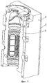
На фиг.1 показана аксонометрическая проекция половины блока, состоящего из формы и ее держателя.Figure 1 shows a perspective view of a half block consisting of a mold and its holder.
На фиг.2 изображена аксонометрическая проекция блока, показанного на фиг.1, в разобранном виде.Figure 2 shows an axonometric projection of the block shown in figure 1, in disassembled form.
На фиг.3 показан выполненный в соответствии с настоящим изобретением держатель формы с системой трубчатых электрических резисторов, прикрепленных к внутренней поверхности указанного держателя формы.Figure 3 shows a mold holder made in accordance with the present invention with a system of tubular electrical resistors attached to the inner surface of said mold holder.
ПОДРОБНОЕ ОПИСАНИЕ ИЗОБРЕТЕНИЯDETAILED DESCRIPTION OF THE INVENTION
Другие задачи и преимущества изобретения будут легко видимыми при ознакомлении с более подробным описанием предпочтительных для настоящего момента времени вариантов реализации изобретения, представленных в сочетании с сопроводительными схематическими чертежами в качестве примеров, не ограничивающих объем правовой охраны настоящего изобретения.Other objects and advantages of the invention will be readily apparent upon reading a more detailed description of the preferred embodiments of the invention, presented in conjunction with the accompanying schematic drawings as examples, not limiting the scope of legal protection of the present invention.
В установках для выдувного формования, пригодных для реализации устройства в соответствии с настоящим изобретением, используются формы, которые относятся к типу пресс-форм с разъемной матрицей (т.е. они разделены на две симметричные половины) и которые открываются для размещения в них предварительно отформованной заготовки и выгрузки отформованного изделия и закрываются при плотном зажиме во время формования.Blow molding machines suitable for implementing the apparatus of the present invention use molds that are of the type of molds with a split die (i.e., they are divided into two symmetrical halves) and which open to accommodate a preformed mold blanks and unloading of the molded product and are closed with a tight clamp during molding.
На фиг.1-3 показана только одна из указанных половин, поскольку допускается, что другая половина является совершенно симметричной. Эта симметрия ограничивается геометрией. На практике, поскольку тепловые обмены с внешней средой являются типично асимметричными, энергия должна подаваться асимметричным способом к двум половинам формы для того, чтобы иметь тепловую симметрию; эта подача контролируется автоматически с помощью системы управления. Результаты термостабилизирующей обработки заключаются в получении равномерности по всей поверхности контейнера, даже если форма контейнера не является симметричной (например, у контейнеров с ручками).Figure 1-3 shows only one of these halves, since it is assumed that the other half is completely symmetrical. This symmetry is limited by geometry. In practice, since heat exchanges with the environment are typically asymmetric, energy must be supplied in an asymmetric way to the two halves of the mold in order to have thermal symmetry; this feed is controlled automatically by the control system. The results of thermostabilizing treatment consist in obtaining uniformity over the entire surface of the container, even if the shape of the container is not symmetrical (for example, containers with handles).
На фиг.1 показана половина обечайки держателя 1 формы, которая содержит в себе половину обечайки формы 2, характерной особенностью которой, в свою очередь, является то, что она имеет внутреннюю полость формы, спрофилированную подобно контейнеру (например, подобно бутылке), подлежащему изготовлению. Термически изолирующая стенка 3 уменьшает потери теплоты, вырабатываемой посредством применения электрических резисторов и уходящей во внешнюю среду.Figure 1 shows half of the shell of the
На фиг.2 показано, что между держателем 1 формы и формой 2, вблизи этой формы 2 размещен первый набор электрических резисторов, которые параллельны друг другу и источнику энергии для формования внутри полости половины 3', 4', 5', 6',7', 8' обечайки, и при этом они соединены друг с другом резисторами 7'', 8'', 9'', 10'', 11'', расположенными в основном поперечно указанным первым резисторам. Расстояние между указанными нагревательными резисторами зависит от мощности, требуемой для нагревания внутренней полости формы до оптимальной температуры, необходимой для выдувного формования. Поперечные нагревательные элементы 7'', 8'', 9'', 10'', 11'' или резисторы расположены вблизи концевых участков вверху и внизу формы. Это размещение осуществляется в связи с тем, что для получения безукоризненных результатов формования необходимо иметь на этих участках определенный уровень охлаждения (например, для предотвращения разрушений в районе горловины контейнера или бутылки) во время формования и увеличенное количество теплоты для компенсации увеличенного рассеивания теплоты, вызываемого значительной кривизной контейнера.Figure 2 shows that between the
Внутри половины обечайки держателя 1 имеется другой трубчатый резистор 3 вместе с поперечным резистором 7 второго набора резисторов, который лучше показан на фиг.3; резисторы указанного второго набора расположены аналогично соответствующим резисторам указанного первого набора.Inside the half shell of the
Указанный первый набор резисторов может быть исключен или отключен, если он не требуется для того типа бутылки, который должен учитываться при ее изготовлении.The specified first set of resistors can be excluded or disabled, if it is not required for the type of bottle that should be taken into account in its manufacture.
На фиг.3 показано подробное размещение различных электрических нагревательных элементов 3, 4, 5, 6 и поперечных электрических нагревательных элементов 7, 8, 9, 10, установленных на внутренней стенке половины обечайки держателя 1.Figure 3 shows the detailed placement of various
Если требуется увеличенное количество теплоты в направлении вдоль боковой стенки контейнера, подлежащего формованию, по сравнению с соседними участками (например, для учета значительных ограничений или деформаций на участке сечения контейнера или бутылки, подлежащих изготовлению), другие поперечные элементы могут использоваться на указанных участках. Эти дополнительные элементы могут быть подобны другим элементам 7, 8, 9, 10, но некоторые резисторы 3, 4, 5, 6 могут формироваться подходящим образом с петлями Очевидно, указанные петли могут располагаться без проблем и при необходимости на каждом участке формы.If an increased amount of heat is required in the direction along the side wall of the container to be molded compared to neighboring sections (for example, to take into account significant restrictions or deformations in the section of the container or bottle section to be manufactured), other transverse elements can be used in these sections. These additional elements may be similar to
Таким образом, легко понять, каким образом при трубчатых электрических резисторах, при необходимости оснащенных петлями, как конкретно указано выше, и соединенных друг с другом на концевых участках с поперечными трубчатыми электрическими резисторами, чрезвычайно просто осуществлять манипулирование с контейнерами и контролировать их производство, особенно бутылок, при реализации термостабилизирующей обработки или процесса термической усадки.Thus, it is easy to understand how, with tubular electrical resistors, if necessary equipped with loops, as specifically indicated above, and connected to each other at the end sections with transverse tubular electrical resistors, it is extremely simple to manipulate containers and control their production, especially bottles when implementing a heat-stabilizing treatment or heat shrink process.
Claims (4)
Applications Claiming Priority (2)
| Application Number | Priority Date | Filing Date | Title |
|---|---|---|---|
| IT000429A ITRM20030429A1 (en) | 2003-09-17 | 2003-09-17 | HEATED BLOWING MOLD FOR THERMO-STABILIZATION PROCESS. |
| ITRM2003A000429 | 2003-09-17 |
Publications (2)
| Publication Number | Publication Date |
|---|---|
| RU2006112403A RU2006112403A (en) | 2006-09-10 |
| RU2380226C2 true RU2380226C2 (en) | 2010-01-27 |
Family
ID=30131575
Family Applications (1)
| Application Number | Title | Priority Date | Filing Date |
|---|---|---|---|
| RU2006112403/11A RU2380226C2 (en) | 2003-09-17 | 2004-09-17 | Blow die with heating for thermostabilising treatment |
Country Status (13)
| Country | Link |
|---|---|
| US (1) | US7775786B2 (en) |
| EP (1) | EP1753597B1 (en) |
| JP (1) | JP4473874B2 (en) |
| CN (1) | CN1852802B (en) |
| AT (1) | ATE395177T1 (en) |
| BR (1) | BRPI0414337B1 (en) |
| CA (1) | CA2538911C (en) |
| DE (1) | DE602004013845D1 (en) |
| ES (1) | ES2305862T3 (en) |
| IT (1) | ITRM20030429A1 (en) |
| MX (1) | MXPA06002886A (en) |
| RU (1) | RU2380226C2 (en) |
| WO (1) | WO2005025835A1 (en) |
Families Citing this family (12)
| Publication number | Priority date | Publication date | Assignee | Title |
|---|---|---|---|---|
| DE202007002873U1 (en) | 2007-02-27 | 2007-04-26 | Krones Ag | Blow mold for producing plastic containers comprises a ring that supports the neck of the container and has a spacer to prevent the body of the container from contacting the inner wall of the mold if the container is tilted |
| DE102010040004A1 (en) * | 2010-08-31 | 2012-03-01 | Krones Aktiengesellschaft | blow |
| FR2984793B1 (en) | 2011-12-23 | 2014-04-25 | Sidel Participations | MOLD FOR FORMING CONTAINERS, EQUIPPED WITH ELECTRIC HEATING SYSTEM COMPRISING A GAME OF SEPARATE RESISTIVE ELEMENTS |
| FR3035019B1 (en) * | 2015-04-15 | 2018-01-26 | Sidel Participations | CONTAINER MOLDING UNIT EQUIPPED WITH A DEPORTE RADIATOR AND AN INTEGRATED TEMPERATURE PROBE |
| FR3038541B1 (en) * | 2015-07-08 | 2017-07-21 | Sidel Participations | MOLDING DEVICE FOR A MACHINE FOR MANUFACTURING THERMOPLASTIC CONTAINERS |
| FR3053906B1 (en) * | 2016-12-12 | 2018-08-17 | Sidel Participations | MOLDING DEVICE FOR IMPLEMENTING HOT MOLDING AND COLD MOLDING PROCESSES |
| DE102017117576A1 (en) * | 2017-08-02 | 2019-02-07 | Krones Ag | Changing process of blow molding by means of changing device |
| US11541589B2 (en) | 2017-08-02 | 2023-01-03 | Krones Ag | Apparatus and method for coupling and uncoupling media couplings on the base mould |
| DE102018120041A1 (en) * | 2018-08-17 | 2020-02-20 | Krones Ag | Device for forming plastic preforms into plastic containers with heating of the blow molds |
| CN109397668A (en) * | 2018-11-30 | 2019-03-01 | 江苏辉河包装机械有限公司 | A kind of bottle blowing mould |
| CN110126240B (en) | 2019-06-20 | 2024-04-19 | 广州达意隆包装机械股份有限公司 | Electric heating die |
| CN111231209A (en) * | 2020-01-17 | 2020-06-05 | 王心悦 | Hollow plastic plate forming device and hollow plate forming process thereof |
Family Cites Families (8)
| Publication number | Priority date | Publication date | Assignee | Title |
|---|---|---|---|---|
| JPS587446B2 (en) * | 1972-09-28 | 1983-02-09 | 呉羽化学工業株式会社 | Netsukaso Seijyuushi no Fukikomi Seikeihouhou Oyobi Souchi |
| JPS5544872A (en) * | 1978-09-28 | 1980-03-29 | Mitsubishi Plastics Ind Ltd | Dust prevention synthetic resin hollow body and its manufacturing method |
| US4839127A (en) * | 1987-03-04 | 1989-06-13 | Owens-Illinois Plastic Products Inc. | Method of making partially crystalline biaxially oriented hollow plastic heat set containers |
| JPH08174552A (en) * | 1992-04-21 | 1996-07-09 | Hakko Denki Seisakusho:Kk | Low thermal mass mold apparatus |
| JPH07314547A (en) * | 1994-05-25 | 1995-12-05 | Denki Kagaku Kogyo Kk | Production of hollow resin container |
| JPH1015944A (en) * | 1996-07-05 | 1998-01-20 | Taiho Kogyo Kk | Apparatus for heating and cooing mold |
| JP2000006232A (en) * | 1998-06-26 | 2000-01-11 | Toyo Seikan Kaisha Ltd | Blow molding die |
| US7034263B2 (en) * | 2003-07-02 | 2006-04-25 | Itherm Technologies, Lp | Apparatus and method for inductive heating |
-
2003
- 2003-09-17 IT IT000429A patent/ITRM20030429A1/en unknown
-
2004
- 2004-09-17 CA CA2538911A patent/CA2538911C/en not_active Expired - Lifetime
- 2004-09-17 EP EP04787168A patent/EP1753597B1/en not_active Expired - Lifetime
- 2004-09-17 AT AT04787168T patent/ATE395177T1/en not_active IP Right Cessation
- 2004-09-17 DE DE602004013845T patent/DE602004013845D1/en not_active Expired - Lifetime
- 2004-09-17 JP JP2006526641A patent/JP4473874B2/en not_active Expired - Fee Related
- 2004-09-17 MX MXPA06002886A patent/MXPA06002886A/en active IP Right Grant
- 2004-09-17 ES ES04787168T patent/ES2305862T3/en not_active Expired - Lifetime
- 2004-09-17 US US10/572,531 patent/US7775786B2/en not_active Expired - Fee Related
- 2004-09-17 CN CN2004800265079A patent/CN1852802B/en not_active Expired - Lifetime
- 2004-09-17 WO PCT/EP2004/052235 patent/WO2005025835A1/en active IP Right Grant
- 2004-09-17 BR BRPI0414337-0A patent/BRPI0414337B1/en not_active IP Right Cessation
- 2004-09-17 RU RU2006112403/11A patent/RU2380226C2/en not_active IP Right Cessation
Also Published As
| Publication number | Publication date |
|---|---|
| DE602004013845D1 (en) | 2008-06-26 |
| EP1753597A1 (en) | 2007-02-21 |
| CN1852802A (en) | 2006-10-25 |
| CA2538911C (en) | 2011-11-01 |
| MXPA06002886A (en) | 2006-06-05 |
| ITRM20030429A1 (en) | 2005-03-18 |
| ES2305862T3 (en) | 2008-11-01 |
| WO2005025835A1 (en) | 2005-03-24 |
| CA2538911A1 (en) | 2005-03-24 |
| ATE395177T1 (en) | 2008-05-15 |
| BRPI0414337B1 (en) | 2014-09-09 |
| RU2006112403A (en) | 2006-09-10 |
| CN1852802B (en) | 2010-04-07 |
| BRPI0414337A (en) | 2006-11-07 |
| ITRM20030429A0 (en) | 2003-09-17 |
| US20070031531A1 (en) | 2007-02-08 |
| JP4473874B2 (en) | 2010-06-02 |
| US7775786B2 (en) | 2010-08-17 |
| JP2007505766A (en) | 2007-03-15 |
| EP1753597B1 (en) | 2008-05-14 |
Similar Documents
| Publication | Publication Date | Title |
|---|---|---|
| RU2380226C2 (en) | Blow die with heating for thermostabilising treatment | |
| US9296147B2 (en) | Method for cooling a mould by circulating a heat-transfer fluid in contact with the external face thereof | |
| JP2010221707A (en) | Thermoforming mold with thermal insulation and associated method | |
| BR112021016137A2 (en) | METHOD FOR TRANSFERRING A NEGATIVE STRUCTURE FROM A SURFACE OF AN INNER WALL OF A BLOW MOLDING TOOL, AND, CONTAINER OF PLASTIC MATERIAL | |
| JPS5998824A (en) | Heat-setting method and device | |
| JPH06179238A (en) | Injection stretch blow molding machine | |
| JP2011506151A (en) | Mold for producing thermoplastic containers and stretch blow molding apparatus provided with such a mold | |
| AU2013223355B2 (en) | Blow molding method, blow mold, and blow-molded container | |
| JP4057487B2 (en) | Crystalline resin continuous molding method and apparatus | |
| JP2837990B2 (en) | Cooling device for plastic molds | |
| JP2005028626A (en) | Method and apparatus for molding resin sheet | |
| JP2002316342A (en) | Preform molding apparatus | |
| US11045993B2 (en) | One-piece mould bottom with optimised fluid circulation | |
| JPH1158448A (en) | Hot runner mold | |
| EP3268206B1 (en) | Methods, assemblies,systems, and intermediate stage pre-assembly multi-chamber containers to make a multi-chamber container | |
| CN221641646U (en) | Hot runner layered heat dissipation device | |
| CN213860470U (en) | Hot runner nozzle structure for PET bottle blank group cavity mold | |
| CN212045702U (en) | Injection mold is used in plastic drum processing with quick cooling function | |
| CN211222019U (en) | Blowing mold with controllable air temperature | |
| WO2023086106A1 (en) | Heated blow mold thread insert for forming threads of a container | |
| JP3052603U (en) | Nozzle part of injection molding machine | |
| CN117507265A (en) | Cooling jacket and hot runner system | |
| JPH0872135A (en) | Blow mold | |
| JPH01165421A (en) | Method and apparatus for molding heat resistant synthetic resin container | |
| JPH0767717B2 (en) | Hot runner mold |
Legal Events
| Date | Code | Title | Description |
|---|---|---|---|
| MM4A | The patent is invalid due to non-payment of fees |
Effective date: 20100918 |