RU2379166C2 - Improvements in welding of structural elements with hollow flanges - Google Patents
Improvements in welding of structural elements with hollow flanges Download PDFInfo
- Publication number
- RU2379166C2 RU2379166C2 RU2006143836/02A RU2006143836A RU2379166C2 RU 2379166 C2 RU2379166 C2 RU 2379166C2 RU 2006143836/02 A RU2006143836/02 A RU 2006143836/02A RU 2006143836 A RU2006143836 A RU 2006143836A RU 2379166 C2 RU2379166 C2 RU 2379166C2
- Authority
- RU
- Russia
- Prior art keywords
- specified
- free edge
- welding
- metal strip
- rollers
- Prior art date
Links
- 238000003466 welding Methods 0.000 title claims abstract description 89
- 238000004519 manufacturing process Methods 0.000 claims abstract description 11
- 230000000694 effects Effects 0.000 claims abstract description 8
- 239000002184 metal Substances 0.000 claims description 45
- 229910052751 metal Inorganic materials 0.000 claims description 45
- 238000000034 method Methods 0.000 claims description 28
- 230000004927 fusion Effects 0.000 claims description 17
- 230000006698 induction Effects 0.000 claims description 16
- 238000005097 cold rolling Methods 0.000 claims description 9
- 229910000831 Steel Inorganic materials 0.000 claims description 6
- 239000010959 steel Substances 0.000 claims description 6
- 230000015572 biosynthetic process Effects 0.000 claims description 5
- 239000011324 bead Substances 0.000 claims description 4
- 238000011144 upstream manufacturing Methods 0.000 claims description 2
- 238000002844 melting Methods 0.000 abstract description 6
- 230000008018 melting Effects 0.000 abstract description 6
- 238000010438 heat treatment Methods 0.000 abstract description 2
- 238000005272 metallurgy Methods 0.000 abstract 1
- 239000000126 substance Substances 0.000 abstract 1
- 230000008569 process Effects 0.000 description 12
- 238000005096 rolling process Methods 0.000 description 8
- 238000006073 displacement reaction Methods 0.000 description 4
- RYGMFSIKBFXOCR-UHFFFAOYSA-N Copper Chemical compound [Cu] RYGMFSIKBFXOCR-UHFFFAOYSA-N 0.000 description 3
- 229910052802 copper Inorganic materials 0.000 description 3
- 239000010949 copper Substances 0.000 description 3
- 230000006378 damage Effects 0.000 description 3
- 238000000465 moulding Methods 0.000 description 3
- 239000002131 composite material Substances 0.000 description 2
- 239000002826 coolant Substances 0.000 description 2
- 239000012634 fragment Substances 0.000 description 2
- 238000012546 transfer Methods 0.000 description 2
- 230000009471 action Effects 0.000 description 1
- 238000013459 approach Methods 0.000 description 1
- 230000008859 change Effects 0.000 description 1
- 239000000498 cooling water Substances 0.000 description 1
- 238000005516 engineering process Methods 0.000 description 1
- 239000011810 insulating material Substances 0.000 description 1
- 230000003993 interaction Effects 0.000 description 1
- 238000012986 modification Methods 0.000 description 1
- 230000004048 modification Effects 0.000 description 1
- 239000012768 molten material Substances 0.000 description 1
- 230000010355 oscillation Effects 0.000 description 1
- 238000013021 overheating Methods 0.000 description 1
- 230000002093 peripheral effect Effects 0.000 description 1
- 230000021715 photosynthesis, light harvesting Effects 0.000 description 1
- 238000002360 preparation method Methods 0.000 description 1
- 238000012545 processing Methods 0.000 description 1
- 229910000859 α-Fe Inorganic materials 0.000 description 1
Images


Classifications
-
- B—PERFORMING OPERATIONS; TRANSPORTING
- B23—MACHINE TOOLS; METAL-WORKING NOT OTHERWISE PROVIDED FOR
- B23K—SOLDERING OR UNSOLDERING; WELDING; CLADDING OR PLATING BY SOLDERING OR WELDING; CUTTING BY APPLYING HEAT LOCALLY, e.g. FLAME CUTTING; WORKING BY LASER BEAM
- B23K11/00—Resistance welding; Severing by resistance heating
- B23K11/08—Seam welding not restricted to one of the preceding subgroups
- B23K11/087—Seam welding not restricted to one of the preceding subgroups for rectilinear seams
- B23K11/0873—Seam welding not restricted to one of the preceding subgroups for rectilinear seams of the longitudinal seam of tubes
-
- B—PERFORMING OPERATIONS; TRANSPORTING
- B21—MECHANICAL METAL-WORKING WITHOUT ESSENTIALLY REMOVING MATERIAL; PUNCHING METAL
- B21D—WORKING OR PROCESSING OF SHEET METAL OR METAL TUBES, RODS OR PROFILES WITHOUT ESSENTIALLY REMOVING MATERIAL; PUNCHING METAL
- B21D19/00—Flanging or other edge treatment, e.g. of tubes
- B21D19/02—Flanging or other edge treatment, e.g. of tubes by continuously-acting tools moving along the edge
-
- B—PERFORMING OPERATIONS; TRANSPORTING
- B21—MECHANICAL METAL-WORKING WITHOUT ESSENTIALLY REMOVING MATERIAL; PUNCHING METAL
- B21D—WORKING OR PROCESSING OF SHEET METAL OR METAL TUBES, RODS OR PROFILES WITHOUT ESSENTIALLY REMOVING MATERIAL; PUNCHING METAL
- B21D5/00—Bending sheet metal along straight lines, e.g. to form simple curves
- B21D5/06—Bending sheet metal along straight lines, e.g. to form simple curves by drawing procedure making use of dies or forming-rollers, e.g. making profiles
- B21D5/10—Bending sheet metal along straight lines, e.g. to form simple curves by drawing procedure making use of dies or forming-rollers, e.g. making profiles for making tubes
- B21D5/12—Bending sheet metal along straight lines, e.g. to form simple curves by drawing procedure making use of dies or forming-rollers, e.g. making profiles for making tubes making use of forming-rollers
-
- B—PERFORMING OPERATIONS; TRANSPORTING
- B23—MACHINE TOOLS; METAL-WORKING NOT OTHERWISE PROVIDED FOR
- B23K—SOLDERING OR UNSOLDERING; WELDING; CLADDING OR PLATING BY SOLDERING OR WELDING; CUTTING BY APPLYING HEAT LOCALLY, e.g. FLAME CUTTING; WORKING BY LASER BEAM
- B23K11/00—Resistance welding; Severing by resistance heating
- B23K11/06—Resistance welding; Severing by resistance heating using roller electrodes
- B23K11/061—Resistance welding; Severing by resistance heating using roller electrodes for welding rectilinear seams
-
- B—PERFORMING OPERATIONS; TRANSPORTING
- B23—MACHINE TOOLS; METAL-WORKING NOT OTHERWISE PROVIDED FOR
- B23K—SOLDERING OR UNSOLDERING; WELDING; CLADDING OR PLATING BY SOLDERING OR WELDING; CUTTING BY APPLYING HEAT LOCALLY, e.g. FLAME CUTTING; WORKING BY LASER BEAM
- B23K13/00—Welding by high-frequency current heating
- B23K13/01—Welding by high-frequency current heating by induction heating
- B23K13/02—Seam welding
- B23K13/025—Seam welding for tubes
-
- B—PERFORMING OPERATIONS; TRANSPORTING
- B23—MACHINE TOOLS; METAL-WORKING NOT OTHERWISE PROVIDED FOR
- B23K—SOLDERING OR UNSOLDERING; WELDING; CLADDING OR PLATING BY SOLDERING OR WELDING; CUTTING BY APPLYING HEAT LOCALLY, e.g. FLAME CUTTING; WORKING BY LASER BEAM
- B23K2101/00—Articles made by soldering, welding or cutting
- B23K2101/04—Tubular or hollow articles
-
- E—FIXED CONSTRUCTIONS
- E04—BUILDING
- E04C—STRUCTURAL ELEMENTS; BUILDING MATERIALS
- E04C3/00—Structural elongated elements designed for load-supporting
- E04C3/02—Joists; Girders, trusses, or trusslike structures, e.g. prefabricated; Lintels; Transoms; Braces
- E04C3/04—Joists; Girders, trusses, or trusslike structures, e.g. prefabricated; Lintels; Transoms; Braces of metal
- E04C2003/0404—Joists; Girders, trusses, or trusslike structures, e.g. prefabricated; Lintels; Transoms; Braces of metal beams, girders, or joists characterised by cross-sectional aspects
- E04C2003/0443—Joists; Girders, trusses, or trusslike structures, e.g. prefabricated; Lintels; Transoms; Braces of metal beams, girders, or joists characterised by cross-sectional aspects characterised by substantial shape of the cross-section
- E04C2003/0452—H- or I-shaped
- E04C2003/0456—H- or I-shaped hollow flanged, i.e. "dogbone" metal beams
Abstract
Description
Область техникиTechnical field
Настоящее изобретение относится к изготовлению холоднокатаных конструктивных элементов с полыми полками в ходе усовершенствованного сварочного процесса.The present invention relates to the manufacture of cold rolled structural elements with hollow shelves during an improved welding process.
В частности, изобретение относится к изготовлению холоднокатаных конструктивных элементов с полыми полками двойного сварного соединения.In particular, the invention relates to the manufacture of cold rolled structural elements with hollow shelves of double welded joints.
Уровень техникиState of the art
Несмотря на то, что из уровня техники известно много балок самых разнообразных конфигураций, большинство этих балок предназначено для какого-либо узкоспециального применения. Однако также из уровня техники известно несколько технических решений, направленных на создание балки общего назначения, способной соперничать со стандартными балками общего назначения, такими как деревянные балки, многослойные деревянные балки, горячекатаные двутавровые балки, широкополочные двутавровые балки и горячекатаные швеллеры.Despite the fact that many beams of the most diverse configurations are known from the prior art, most of these beams are intended for some highly specialized application. However, several technical solutions are also known from the prior art aimed at creating general-purpose beams that can compete with standard general-purpose beams, such as wooden beams, multilayer wooden beams, hot-rolled I-beams, wide-flange I-beams and hot-rolled channels.
Примеры балок специального применения приведены в американских патентах 5012626, 3362056 и 6415577, описывающих композитные балки, имеющие рифленую стенку и плоские полые полки или полые полки прямоугольного поперечного сечения. В австралийском патенте 716272 описана ферма, содержащая пояса с полыми полками.Examples of beams for special applications are given in US patents 5012626, 3362056 and 6415577, describing composite beams having a corrugated wall and flat hollow shelves or hollow shelves of rectangular cross section. Australian patent 716272 describes a farm containing hollow-belt belts.
В последующие годы выяснилось, что в ситуациях с относительно небольшой нагрузкой вместо горячекатаных секций предпочтительно использовать холодногнутые продольные балки С-, Z- и J-образного сечения, так как они обычно имеют очень хорошую несущую способность по сечению на единицу массы. Такие холодногнутые балки имеют значительные ограничения на несущую способность по моменту при увеличении длины балки, обусловленные опасностью разрушения вследствие потери формы. Холодногнутые балки J- и I- или Н-образного сечения проиллюстрированы в британских патентах 2093886 и 2102465, тогда как конструктивный элемент С-образного сечения описан в международной публикации 96/23939.In subsequent years, it turned out that in situations with a relatively small load, instead of hot-rolled sections, it is preferable to use cold-formed longitudinal beams of C-, Z- and J-shaped section, since they usually have very good load-carrying capacity per section per unit mass. Such cold-formed beams have significant limitations on the moment-carrying capacity with increasing length of the beam, due to the danger of destruction due to loss of shape. Cold-formed J- and I- or H-shaped beams are illustrated in British Patents 2093886 and 2102465, while a C-shaped structural member is described in
Для повышения эффективности сечения холодокатаных продольных балок было предложено использовать полые полки, в результате чего сечение полок увеличивается без сопутствующего или по меньшей мере значительного увеличения массы балки на единицу длины.To increase the efficiency of the section of cold-rolled longitudinal beams, it was proposed to use hollow shelves, as a result of which the section of the shelves increases without a concomitant or at least a significant increase in the mass of the beam per unit length.
Примеры опорных конструкций с полыми полками показаны в американском патенте 3342007, российском авторском свидетельстве 827723 и американском патенте 3698224, во всех из них описаны балки с полыми "открытыми" полками треугольного сечения, т.е. в этих балках нет непрерывного сварочного шва, улучшающего прочность полок на скручивание.Examples of supporting structures with hollow shelves are shown in US patent 3342007, Russian copyright certificate 827723 and US patent 3698224, all of which describe beams with hollow "open" shelves of triangular section, i.e. these beams do not have a continuous weld that improves the torsional strength of the shelves.
В американских патентах 5163225 и 5373679, права на которые уступлены заявителю настоящей заявки, впервые описаны холодногнутые балки с полыми полками, изготовленные путем двойной сварки с образованием «закрытых» полок кольцевого сечения, где свободные края полок приварены к центральной стенке вдоль ее краев. После этапа сварки по существу кольцевые полки можно формовать, придавая им самые различные поперечные сечения, например прямоугольные, шестиугольные, треугольные и т.п. Балки с полыми полками треугольного поперечного сечения известны на рынке как балки Dogbone (зарегистрированный товарный знак).In US patents 5163225 and 5373679, the rights to which are assigned to the applicant of this application, for the first time, cold-formed beams with hollow shelves, made by double welding to form “closed” shelves of circular section, where the free edges of the shelves are welded to the central wall along its edges, are described for the first time. After the welding step, substantially annular shelves can be molded to give them a wide variety of cross sections, for example rectangular, hexagonal, triangular, and the like. Beams with hollow shelves of triangular cross-section are known on the market as Dogbone beams (registered trademark).
Несмотря на то, что при применении двойной сварки по ее обычному назначению она показывает хорошие результаты, при попытке использовать ее для изготовления балок Dogbone возникает множество проблем - особенно страдает стабильность сварочного шва. Также, из-за чрезмерной стоимости оборудования, имеются ограничения на размер поперечных сечений полки. Согласно одному из известных вариантов балки разрушение шва под нагрузкой происходит вследствие чрезмерной деформации закаленной зоны сварки в формующей клети стана.Despite the fact that when applying double welding for its usual purpose, it shows good results, when trying to use it for the manufacture of Dogbone beams, many problems arise - the stability of the weld is especially affected. Also, due to the excessive cost of equipment, there are restrictions on the size of the cross sections of the shelf. According to one of the known beam options, the destruction of the weld under load occurs due to excessive deformation of the hardened welding zone in the forming mill stand.
В данной заявке термин "ERW" обозначает электрическую контактную или индукционную сварку, осуществляемую либо посредством контактов, либо индукционных катушек/импедеров для создания тока в элементе, а также другие формы электрической контактной сварки.In this application, the term "ERW" means electric contact or induction welding, carried out either through contacts or induction coils / impeders to create current in the cell, as well as other forms of electric contact welding.
Таким образом, целью данного изобретения является по меньшей мере частичное преодоление недостатков известного способа двойной сварки Dogbone и разработка нового способа сварки, пригодного для изготовления холодногнутых стальных конструктивных элементов с полыми полками.Thus, the aim of the present invention is to at least partially overcome the disadvantages of the known Dogbone double welding method and to develop a new welding method suitable for the manufacture of cold-formed steel structural elements with hollow shelves.
Сущность изобретенияSUMMARY OF THE INVENTION
Согласно первому аспекту изобретения предложен способ сварки в одну линию стальных конструктивных элементов с полыми полками на холоднопрокатном стане, включающий следующие этапы:According to a first aspect of the invention, there is provided a method of welding in a single line steel structural elements with hollow shelves on a cold rolling mill, comprising the following steps:
образование профильной поверхности, смежной по меньшей мере одному краю металлической полосы;the formation of a profile surface adjacent to at least one edge of the metal strip;
приваривание в ходе процесса ERW (электрическая контактная или индукционная сварка) свободного края указанной металлической полосы, смежного указанной профильной поверхности, к поверхности этой металлической полосы с получением полой полки, проходящей вдоль стороны стенки; данный способ характеризуется тем, что указанный свободный край линейно выравнивают вдоль заданной линии сплавления на указанной поверхности полосы и направляют этот по меньшей мере один свободный край по заданной прямолинейной траектории по линии приближения к результирующему сварному соединению, проходящему между указанным по меньшей мере одним свободным краем и указанной поверхностью, при этом энергию, сообщаемую указанному холодногнутому конструктивному элементу, фокусируют, за счет эффекта близости, по указанной заданной линии сплавления на указанной поверхности до приваривания к ней указанного свободного края.welding during the ERW process (electric contact or induction welding) the free edge of the indicated metal strip adjacent to the specified profile surface to the surface of this metal strip to obtain a hollow shelf extending along the side of the wall; This method is characterized in that said free edge is linearly aligned along a predetermined fusion line on said strip surface and this at least one free edge is guided along a predetermined straight path along the line of approximation to the resulting welded joint passing between said at least one free edge and the specified surface, while the energy communicated to the specified cold-formed structural element, focus, due to the proximity effect, on the specified predetermined line fusion on said surface prior to welding it to said free edge.
При необходимости, указанный свободный край выравнивают относительно указанной линии сплавления посредством по меньшей мере одного шовного ролика, имеющего кольцевой буртик, обеспечивающий опору для указанного свободного края.If necessary, the specified free edge is aligned with the specified fusion line by means of at least one suture roller having an annular bead providing support for the specified free edge.
Указанный свободный край металлической полосы можно вводить в прижим к указанному кольцевому буртику посредством фасонного направляющего ролика.The specified free edge of the metal strip can be introduced into the clamp to the specified annular flange by means of a shaped guide roller.
Во время того как указанный по меньшей мере один свободный край входит в прижим к указанному кольцевому буртику, указанную полосу металла удерживают в центральной ее части поверхностями противолежащих цилиндрических роликов, смежных указанному участку сварки.While the specified at least one free edge enters the clamp to the specified annular flange, the specified strip of metal is held in its central part by the surfaces of opposite cylindrical rollers adjacent to the specified section of the weld.
Шовные ролики могут быть установлены с возможностью регулировки для обеспечения направления указанного свободного края к указанному участку смыкания под заданным углом к указанной поверхности полосы.Suture rollers can be set with the possibility of adjustment to ensure the direction of the specified free edge to the specified section of the closure at a given angle to the specified surface of the strip.
В предпочтительном случае указанный свободный край металлической полосы направляют по указанной заданной траектории при помощи фасонного прижимного ролика, проходящего по указанной профильной поверхности металлической полосы, расположенной между разнесенными по существу параллельными контактными поверхностями этого фасонного прижимного ролика.Preferably, said free edge of the metal strip is guided along said predetermined path using a shaped pinch roller extending along said profile surface of the metal strip located between the spaced apart substantially parallel contact surfaces of this shaped pinch roller.
Указанную свободному концу и заданному участку сварки энергию сварки можно сообщать посредством индукционной катушки, соединенной с источником электрического тока, причем указанная катушка проходит по существу вокруг указанной металлической полосы в плоскости, по существу перпендикулярной ее продольной оси.Said free end and a predetermined welding portion, the welding energy can be communicated by means of an induction coil connected to an electric current source, said coil extending substantially around said metal strip in a plane substantially perpendicular to its longitudinal axis.
При необходимости, во внутреннюю полость указанной профильной поверхности, в смежную указанному участку смыкания зону, где указанный свободный край приваривают к указанной поверхности металлической полосы, может проходить удлиненный стержневидный индукционный импедер, поддерживаемый с одного конца.If necessary, an elongated rod-shaped induction impeder supported from one end can pass into the internal cavity of the specified profile surface, adjacent to the specified section of the clamping area, where the specified free edge is welded to the specified surface of the metal strip.
Согласно другому аспекту изобретения предложен аппарат для ERW-сварки в одну линию (электрическая контактная или индукционная сварка) стальных конструктивных элементов с полыми полками на холоднопрокатном стане, содержащий:According to another aspect of the invention, there is provided an apparatus for ERW welding in a single line (electric contact or induction welding) of steel structural elements with hollow shelves in a cold rolling mill, comprising:
клеть шовных роликов, удерживающую с возможностью вращения по меньшей мере один шовный ролик, выполненный с возможностью линейного выравнивания свободного края профильной металлической полосы вдоль заданной линии сплавления, расположенной на расстоянии от указанного свободного края на поверхности указанной металлической полосы;a cage of suture rollers holding rotatably at least one suture roller configured to linearly align the free edge of the profile metal strip along a predetermined fusion line located at a distance from the specified free edge on the surface of the specified metal strip;
клеть сварочной камеры, удерживающую с возможностью вращения по меньшей мере одну пару прижимных роликов, предназначенных для направления указанного свободного края, нагретого до заданной температуры, в зону сварки с соответствующе нагретой указанной линией сплавления на указанной поверхности, причем при использовании указанная пара прижимных роликов совместно направляет указанный свободный край по заданной прямолинейной траектории по существу вдоль линии приближения к результирующему сварному соединению, проходящему между указанным свободным краем и указанной поверхностью металлической полосы, при этом энергия, сообщаемая указанному холодногнутому конструктивному элементу, фокусируется, за счет эффекта близости, по указанной заданной линии сплавления на указанной поверхности.a cage of the welding chamber holding rotatably at least one pair of pinch rollers designed to direct the specified free edge heated to a predetermined temperature into the weld zone with a correspondingly heated specified fusion line on the specified surface, and when using the specified pair of pinch rollers together directs the specified free edge along a given rectilinear path essentially along the line of approximation to the resulting welded joint, passing between the decree nym free edge and said surface of the metal strip, wherein the energy imparted to said cold formed structural member focuses, due to the proximity effect at said predetermined weld line on said surface.
На указанных свободном крае и участке сварки указанный электрический ток возбуждается посредством токоподводов, скользяще взаимодействующих с указанной металлической полосой и смежных этим свободному краю и участку сварки.At the indicated free edge and the weld area, the specified electric current is excited by current leads, slidingly interacting with the specified metal strip and adjacent to this free edge and the weld area.
В предпочтительном случае на указанных свободном крае и участке сварки указанный электрический ток возбуждается посредством индукционной катушки, поперечно окружающей указанную металлическую полосу в плоскости, перпендикулярной направлению движения указанной металлической полосы через эту катушку.In a preferred case, at the indicated free edge and the weld area, said electric current is excited by an induction coil transversely surrounding said metal strip in a plane perpendicular to the direction of movement of said metal strip through this coil.
В предпочтительном случае по меньшей мере одна указанная пара прижимных роликов установлена с возможностью углового регулирования в плоскости, перпендикулярной направлению движения указанной полосы металла между этими роликами.In the preferred case, at least one of the specified pair of pinch rollers is mounted with the possibility of angular adjustment in a plane perpendicular to the direction of motion of the indicated strip of metal between these rollers.
По меньшей мере одна из указанных пар прижимных роликов может быть выполнена регулируемой относительно другой из указанных пар роликов в направлении, перпендикулярном оси вращения этой по меньшей мере одной пары прижимных роликов.At least one of these pairs of pinch rollers can be made adjustable relative to the other of these pairs of rollers in a direction perpendicular to the axis of rotation of this at least one pair of pinch rollers.
Указанная сварочная камера содержит ролики для поддержки стенки, установленные с возможностью вращения относительно соответствующих параллельных осей, перпендикулярных направлению движения элемента из металлической полосы между ними.The specified welding chamber contains rollers for supporting the wall, mounted for rotation relative to the respective parallel axes, perpendicular to the direction of movement of the element from the metal strip between them.
При необходимости, ролик для поддержки стенки может иметь фасонный внешний край и действовать в качестве одного ролика из указанной пары прижимных роликов.If necessary, the roller for supporting the wall may have a shaped outer edge and act as one roller from the specified pair of pressure rollers.
Аппарат может содержать более одной клети шовных роликов.The device may contain more than one stand of suture rollers.
При необходимости, по меньшей мере одна из указанных клетей шовных роликов содержит шовный ролик с кольцевым буртиком, обеспечивающим опору для указанного свободного края металлической полосы.If necessary, at least one of the indicated stands of the suture rollers comprises a suture roller with an annular bead providing support for the indicated free edge of the metal strip.
Кроме того, имеется фасонный направляющий ролик, предназначенный для введения указанного свободного края металлической полосы в прижим к указанному кольцевому буртику.In addition, there is a shaped guide roller for introducing the specified free edge of the metal strip into the clip to the specified annular collar.
При необходимости, во внутреннюю полость профильного краевого участка указанной металлической полосы проходит стержневидный импедер, удерживаемый с одного из его концов и расположенный выше по ходу технологического процесса от указанной по меньшей мере одной клети шовных роликов.If necessary, a rod-shaped impedor held from one of its ends and located upstream of the at least one suture roll stand is passed into the internal cavity of the profile edge portion of said metal strip.
Краткое описание чертежейBrief Description of the Drawings
Далее изобретение описано более подробно на примере предпочтительных вариантов его выполнения, раскрытых со ссылкой на прилагаемые чертежи, на которых:The invention is further described in more detail by way of example of preferred embodiments disclosed with reference to the accompanying drawings, in which:
фиг.1 упрощенно изображает холоднопрокатный стан, предназначенный для формования конструктивных элементов с полыми полками.figure 1 simplified depicts a cold rolling mill designed for forming structural elements with hollow shelves.
фиг.2 упрощенно иллюстрирует процесс двойной сварки, соответствующий предшествующему уровню техники;figure 2 simplified illustrates the process of double welding corresponding to the prior art;
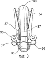
фиг.3 упрощенно изображает фрагмент известных из уровня техники прижимных роликов, расположенных в сварочной камере холоднопрокатного стана;figure 3 simplified depicts a fragment of the prior art pressure rollers located in the welding chamber of a cold rolling mill;
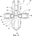
фиг.4 упрощенно изображает увеличенный фрагмент поперечного сечения ролика сварочной камеры, показанной на фиг.4;figure 4 is a simplified depicts an enlarged fragment of a cross section of the roller of the welding chamber shown in figure 4;
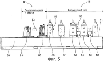
фиг.5 изображает вертикальный вид сбоку части холоднопрокатного стана, содержащей клеть формующих роликов, клеть сварочных роликов и клеть сварочной камеры;5 is a vertical side view of a portion of a cold rolling mill comprising a stand of forming rollers, a stand of welding rollers and a stand of a welding chamber;
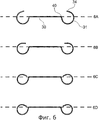
фиг.6 в пошаговом исполнении иллюстрирует часть процесса создания балки с полыми полками, начиная с последних стадий формования и заканчивая стадией подачи в сварочную камеру;6 in a step-by-step manner illustrates part of the process of creating a beam with hollow shelves, starting from the last stages of molding and ending with the stage of feeding into the welding chamber;
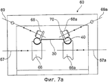
фиг.7а и 7b сзади и спереди упрощенно иллюстрируют конфигурацию клети шовнаправляющих роликов;figa and 7b back and front simplified illustrate the configuration of the cage of suture guide rollers;
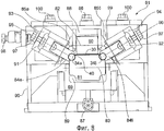
фиг.8 упрощенно изображает конфигурацию клети сварочной камеры;Fig. 8 depicts a simplified configuration of the stand of a welding chamber;
фиг.9 упрощенно изображает конфигурацию роликов клети сварочной камеры, показанной на фиг.8;Fig.9 is a simplified depiction of the configuration of the rollers of the stand of the welding chamber shown in Fig.8;
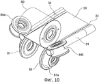
фиг.10 дает упрощенное фантомное аксонометрическое изображение роликов в клети сварочной камеры, показанной на фиг.8;figure 10 gives a simplified phantom axonometric image of the rollers in the stand of the welding chamber shown in Fig;
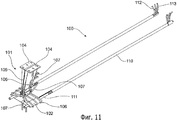
фиг.11 упрощенно иллюстрирует конфигурацию и взаимное расположение индукционной катушки и импедеров;11 simplistically illustrates the configuration and relative position of the induction coil and impeders;
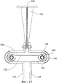
фиг.12 упрощенно изображает поперечное сечение показанного на фиг.12 узла индукционная катушка/импедер, находящегося в использовании при расположении в нем секции полой полки;12 is a simplified cross-sectional view of the assembly of the induction coil / impedor shown in FIG.
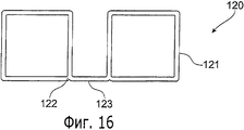
и фиг.13-16 изображают профили конструктивных элементов с полыми полками, выполненных предложенным способом с использованием заявленного аппарата.and Fig.13-16 depict profiles of structural elements with hollow shelves made by the proposed method using the claimed apparatus.
Для ясности отметим, что на представленных чертежах аналогичные элементы обозначены одинаковыми номерами позиций.For clarity, we note that in the drawings, similar elements are denoted by the same reference numbers.
Подробное описание изобретенияDETAILED DESCRIPTION OF THE INVENTION
На фиг.1 схематично представлена типичная конфигурация роликового прокатного стана, предназначенного для изготовления конструктивных элементов с полыми полками, примеры которых показаны на фиг.11-14. Не вдаваясь в излишние подробности, отметим, что прокатный стан включает в себя формирующий узел 11, сварочный узел 12 и профилирующий узел 13.Figure 1 schematically shows a typical configuration of a rolling mill intended for the manufacture of structural elements with hollow shelves, examples of which are shown in figures 11-14. Without going into too much detail, we note that the rolling mill includes a forming
Формирующий узел 11 содержит чередующие друг друга приводные клети 14 и клети 15 формирующих роликов. Приводные клети 14 объединены в обычную приводную линию прокатного стана (не показана), однако здесь вместо фасонных формирующих роликов используются гладкие цилиндрические ролики, зажимающие стальную полосу 16 в ее центральной зоне, соответствующей стенке создаваемой балки. Клети 15 формирующих роликов представлены парой отдельных элементов 15а, 15b, каждый из которых оснащен фасонными роликами, выполненными с возможностью формирования полых полок на противоположных сторонах металлической полосы 16 при ее прохождении через формирующий узел. Поскольку клети 15а, 15b формирующих роликов не требуется соединять с приводной линией, как это происходит в обычных холоднопрокатных станах, то клети формирующих роликов можно легко регулировать перпендикулярно продольной оси прокатного стана и тем самым адаптировать их к условиям производства балок самой разной ширины.The forming
После придания полосе 16 требуемого поперечного сечения эту полосу с отформованными краями подают в сварочный узел 12, где свободные края участков с отформованными краями вводят в соприкосновение со стенкой под предварительно заданным углом и воздействуют на них сварочным аппаратом ERW. Для более точного размещения свободных краев относительно требуемой линии сварки формованную полосу подают в зону аппарата ERW (упрощенно показанного позицией 17а) при помощи клети 17 шовнаправляющих роликов. После нагрева краев полосы и линии сварного шва на поверхности ленты до температуры плавления полосу пропускают через клеть 18 сварочной камеры, воздействующую на указанные нагретые участки и способствующую их сварочному соединению с образованием замкнутых полок. Сваренную секцию замкнутой полки затем пропускают через ряд клетей 19 приводных роликов и клетей 20 профилирующих роликов, придающих ее поперечному сечению желаемую форму полки, а в завершении - через обычную клеть 21 туркоголовых роликов для окончательной выправки, причем отсюда обрабатываемая полоса выходит уже в виде балки 22 с полыми полками, сваренной методом двойной сварки. Сварочный аппарат ERW индуцирует в свободных краях полосы ток, возникающий также и на соответствующих смежных участках балочной стенки благодаря близости к ней указанных свободных краев. Поскольку тепловая энергия на участке стенки может рассеиваться двунаправленно, в отличие от свободного края полки, то для сообщения стенке достаточной температуры, обеспечивающей возможность ее приваривания к свободному краю, необходимо приложить дополнительную энергию.After giving the desired cross-section to strip 16, this strip with molded edges is fed into the
Было обнаружено, что традиционные технологии прокатки и сварки ERW требуют для нагрева участка стенки до температуры плавления такое количество энергии, которое вызывает расплавление свободного края полки и его растекание вне пределов желаемой линии сварного шва. В результате происходящей потери расплавленного материала площадь поперечного сечения полки значительно уменьшается, и контроль за кромкой полосы в точке сварки становится более трудным.It was found that traditional ERW rolling and welding technologies require to heat such a portion of the wall to the melting temperature that the amount of energy that causes the free edge of the shelf to melt and spread outside the desired weld line. As a result of the loss of molten material, the cross-sectional area of the shelf is significantly reduced, and controlling the edge of the strip at the weld point becomes more difficult.
Фиг.2 упрощенно иллюстрирует высокочастотную сварку ERW по предшествующему уровню техники.Figure 2 simplistically illustrates the high frequency welding of ERW in the prior art.
Показанная на фиг.2 стенка 30 выполнена имеющей дугообразный профиль, чтобы таким образом минимизировать протяженность, с которой должны быть выполнены полые полки 31 путем приведения их свободных краев в соприкосновение с краем стенки 30. Вблизи свободного края 34 каждой полки 31 и вблизи края стенки, на котором предполагается сделать сварной шов, расположены пары токоподводов 32 и 33, соединенные с соответствующими источниками 34 переменного тока высокой частоты. Как можно видеть, свободный край 34 каждой полой полки 31 примыкает к линии сварного шва 35 под углом к ней как в вертикальной, так и в горизонтальной плоскости.The
На фиг.3 проиллюстрирована типичная конфигурация известной сварочной камеры, боковые ролики 36 которой направляют отформованные полки 31 внутрь в горизонтальном направлении, в то время как фасонные прижимные ролики 37, совместно с нижним роликом 38, направляют нагретые свободные края полок в соприкосновение с нагретым участком края стенки 30 для осуществления сварки между ними.Figure 3 illustrates a typical configuration of the known welding chamber, the
Общие усилия, прилагаемые к свободным краям полок боковыми роликами 36 и прижимными роликами 37, обеспечивают заворачивание секции полки, уменьшая ее диаметр.The total efforts exerted on the free edges of the shelves by the
Фиг.4 представляет собой увеличенный вид поперечного сечения ролика сварочной камеры, показанной на фиг.3. Перед поступлением в сварочную камеру, обозначенную в целом позицией 39, свободные края 34 полок 31 располагаются на расстоянии над предполагаемым конечным положением 40 сварочных швов на полосе металла 30 (как показано на разрезе в несколько преувеличенном виде фантомной линией). Когда формуемая секция проходит через узел 39 роликов сварочной камеры, свободные края 34 полых полок 31 направляются вниз и внутрь за счет общего давления совместно действующих роликов 36, 37, 38, при этом свободные концы 34 «волочатся» по поверхности стенки 30 до тех пор, пока не войдут в контакт с ее поверхностью в соответствующем положении 40 сварочного шва.Figure 4 is an enlarged cross-sectional view of the roller of the welding chamber shown in figure 3. Before entering the welding chamber, generally indicated by 39, the
Во время «волочащегося» движения свободных краев 34 тепловое «пятно», возникшее на полке вследствие близости свободных краев 34, двигается во внешнем направлении от положения 41, определяющегося кратчайшим расстоянием между свободным краем 34 и верхней поверхностью стенки, по направлению к положению 40 сварочного шва, в котором происходит плавление. Из-за невозможности сфокусировать тепло вследствие упомянутого эффекта близости в крайнем месте сварочного шва, существенное количество тепловой энергии рассеивается на стенке и прилегающих участках полых полок.During the “dragging” movement of the
Для преодоления проблемы рассеивания энергии было предложено увеличивать подачу электрической энергии, компенсируя потери, однако это привело к перегреву свободного края стенки, а следовательно - к потере металла свободного края полки из-за плавления. Более того, необходимость перегрева края полки для передачи достаточного тепла краю стенки с целью получить приемлемое сварочное соединение усугубляется проблемой коробления краев, нарушающей стабильность сварки.To overcome the problem of energy dissipation, it was proposed to increase the supply of electrical energy, compensating for losses, however, this led to overheating of the free edge of the wall, and therefore to loss of metal on the free edge of the shelf due to melting. Moreover, the need to overheat the edge of the shelf to transfer sufficient heat to the edge of the wall in order to obtain an acceptable welding connection is exacerbated by the problem of warping the edges, violating the stability of welding.
Теперь известно, что вышеупомянутые трудности можно преодолеть выравнивая нагретый свободный край полки по намеченной линии сварки, а затем вводя свободный край полосы в соприкосновение с нагретым участком стенки по прямой траектории в направлении, соответствующем требуемому углу наклона между участком стенки и участком края полки вблизи сварного шва. Направляя свободный край полки вдоль этой заданной траектории можно избежать проблемы передачи тепла в неоправданно широкой полосе, выходящей за границы линии сварки, обусловленной указанным эффектом "волочения" во время вращения полки в прижимных роликах, когда происходит выравнивание свободного края по желаемой линии сварки.It is now known that the aforementioned difficulties can be overcome by aligning the heated free edge of the shelf along the intended welding line, and then bringing the free edge of the strip into contact with the heated wall section along a straight path in the direction corresponding to the required angle of inclination between the wall section and the shelf edge section near the weld . By directing the free edge of the flange along this predetermined path, the problem of heat transfer in an unjustifiably wide strip extending beyond the boundaries of the welding line due to the indicated “drawing” effect during rotation of the shelf in the pressure rollers when the free edge is aligned with the desired welding line can be avoided.
Такой улучшенный контроль за процессом контактной или индукционной сварки, выполняемый согласно предложенному способу и с использованием предложенного аппарата, привел к повышению эффективности производства и обеспечению значительно лучших производственных допусков при создании конструктивных элементов с полыми полками с двойным сварочным швом.Such improved control of the contact or induction welding process, performed according to the proposed method and using the proposed apparatus, has led to increased production efficiency and to provide significantly better manufacturing tolerances when creating structural elements with hollow shelves with a double welding seam.
Фиг.5 изображает вертикальный вид сбоку части показанного на фиг.1 холоднопрокатного стана, содержащего формующий узел 11 и узел 12 подготовки краев и сварки.FIG. 5 is a side elevational view of a portion of the cold rolling mill shown in FIG. 1, comprising a forming
Как следует из фиг.5, на основании 50 стана установлен приводной формующий ролик 51, клеть 52 холостых роликов, неприводная клеть 53 формования краев, другая клеть 54 холостых роликов, импедерная скоба 55, неприводная клеть 56 формования краев, другая неприводная клеть 56 формования краев, клеть 58 приводных формующих роликов с боковыми роликами 59, шестироликовая клеть 60 шовнаправляющих роликов и четырехроликовая клеть 61 сварочной камеры. Между клетями 60 и 61 расположена катушка 62 индуктора.As follows from FIG. 5, on the base of the mill, a
Фиг.6 в пошаговом исполнении иллюстрирует процесс создания конструктивного элемента с полыми полками на показанном на фиг.5 стане.Fig.6 in a step-by-step execution illustrates the process of creating a structural element with hollow shelves in the mill shown in Fig.5.
Часть 6А иллюстрирует форму на выходе из прокатной клети 53, часть 6В иллюстрирует форму на выходе из прокатной клети 58, часть 6С иллюстрирует форму на выходе из прокатной клети 60 и часть 6D иллюстрирует форму формованной роликами секции непосредственно перед подачей в клеть 61 сварочной камеры. Как следует из чертежей, траектория свободного края 34 полой полки 31 следует наикратчайшему пути между краем 34 и краем 40 полки 30, и по мере того как данная секция достигает клети 60 шовнаправляющих роликов, поперечное сечение полой полки принимает по существу овальную форму, показанную на 6С. Также можно видеть, что край 34 полки занимает стабильное положение относительно края 40 стенки 30 в зоне индукционной катушки 62.
Фиг.7 упрощенно иллюстрирует конфигурацию показанной на фиг.5 клети 60 шовнаправляющих роликов, причем фиг.7а является вертикальным изображением сзади по ходу технологического процесса, а фиг.7b - вертикальным изображением спереди по ходу технологического процесса.Fig. 7 simplifies illustrating the configuration of the
На фиг.7а упрощенно показано вертикальное изображение сзади по ходу технологического процесса клети 60 шовнаправляющих роликов. Эта клеть 60 содержит опорную раму 65, на задней поверхности которой имеется пара независимо установленных фасонных опорных роликов 66 и 66а, каждый из которых расположен на подшипнике с возможностью вращения относительно совмещенных осей 67 и 67а, и шовнаправляющие ролики 68 и 68а, установленные на подшипниках с возможностью вращения относительно соответствующих наклонных осей 69 и 69а. Шовнаправляющие ролики 68 и 68а предназначены для выравнивания свободных краев 34а и 34b полых полок 31 и 31 в продольном направлении по желаемой линии сварки, по мере того как холодногнутая секция приближается к прижимным роликам сварочной камеры 61.On figa simplified vertical image is shown behind in the course of the technological process of the
Со своих внутренних краев шовнаправляющие ролики 68 и 68а имеют периферические края 70 с отбортовкой, которые служат опорой для свободных краев 34 полых полок и могут направлять края полок для их совмещения с краями 40 стенки 30.From their inner edges, the
Шовнаправляющие ролики 68 и 68а и опорные ролики 66 и 66а выполнены с возможностью смещения по оси, что позволяет адаптировать их к конструктивным элементам с полыми полками различных размеров. Кроме того, шовнаправляющие ролики 68 и 68а могут быть установлены на опорной раме 65 шарнирно.The
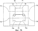
На фиг.7b клеть 60 шовнаправляющих роликов показана спереди по ходу технологического процесса. Внутри дугообразной рамы 65 расположены цилиндрический шовнаправляющий ролик 71 и цилиндрический опорный ролик 72, каждый из которых установлен на подшипнике с возможностью вращения относительно соответствующих осей 73 и 74. Опорный ролик 72 имеет фасонные торцевые участки 72а, предназначенные для размещения полых полок 31, в то время как концы 75 и 76 шовнаправляющего ролика, имеющие отбортовку, располагаются сверху внутренних краев 40 стенки 30, при этом свободные края 34 полых полок 31 опираются на плоские торцы ролика 71. Стенка 30 прочно зажата между цилиндрическими участками роликов 71 и 72 для предотвращения ее искривления, особенно искривления прилегающих краев 40.7b, a
Фиг.8 изображает конфигурацию четырехроликовой сварочной камеры 61, показанной на фиг.5.FIG. 8 shows a configuration of a four-
Сварочная камера 61 содержит цилиндрический верхний ролик 80 и цилиндрический нижний ролик 81 с фасонными краями 81а, причем каждый из роликов 80 и 81 установлен на подшипнике с возможностью вращения относительно соответствующих осей 82 и 83. Фасонные прижимные ролики 84а и 84b вращаются относительно соответствующих наклонных осей 85а и 85b и выполнены с возможностью направления нагретых свободных краев 34а и 34b полых полок 31 на соответствующие нагретые участки по линиям сварки вдоль противоположных границ 40 стенки 30, чтобы обеспечить сплавление между ними с получением непрерывного сварочного шва. Следует отметить, что полости между прижимными роликами 84а и 84b и соответствующими фасонными краями 81 цилиндрического опорного ролика 81 имеют овальную форму, сходную с формой поперечного сечения полых полок 31, показанных на фиг.6 в части 6D.The
Свободные края 34а и 34b направляются на соответствующие линии сварки линейным образом, перпендикулярно соответствующим осям 85а и 85b вращения прижимных роликов 84а и 84b, причем направляются без поперечного «волочащегося» действия, в результате чего индукционные «пятна» или пути к желаемым положениям сварочных швов между соответствующими свободными краями 34а и 34b и противоположными границами 40 стенки 30 остаются фиксированными.The
Цилиндрические ролики 80 и 81 установлены с возможностью смещения в вертикальной плоскости посредством соответствующих регулировочных винтов 86 и 87, причем винты 86 и 87 соединены с соответствующими подушками 88 и 89 роликов, установленными на опорной раме 90 с возможностью перемещения скольжением.The
Прижимные ролики 84а и 84b установлены с возможностью перемещения скольжением в соответствующих подушках 91 и 92 соответствующих опорных рам 93 и 94 прижимных роликов, что позволяет регулировать их положение скольжением вдоль соответствующих осей 95 и 96 скольжения при помощи регулировочных винтов 97. В свою очередь, опорные рамы 93 и 94 прижимных роликов установлены с возможностью смещения в поперечном направлении посредством винта 98, соединенного с опорными рамами 93, 94 резьбовым стержнем 99, и с возможностью смещения в вертикальном направлении посредством винтов 100. В предпочтительном случае опорные рамы роликов установлены на раме 90 шарнирно с возможностью поворота относительно соответствующих осей, параллельных направлению движения конструктивных элементов с полыми полками по клети 61 сварочной камеры.The
То обстоятельство, что ролики установлены с возможностью регулировки, позволяет сваривать в сварочной камере конструктивные элементы с полыми полками самых различных размеров и сечений, с исключительно точным контролем траектории, по которой свободные края полых полок движутся к точно позиционированной линии сварного шва, проходящей смежно стенке или по ее краям.The fact that the rollers are mounted with the possibility of adjustment makes it possible to weld structural elements with hollow shelves of various sizes and sections in the welding chamber, with extremely precise control of the path along which the free edges of the hollow shelves move to a precisely positioned weld line running adjacent to the wall or along its edges.
Фиг.9 упрощенно изображает конфигурацию роликов в показанной на фиг.8 сварочной камере 61. Этот чертеж более наглядно иллюстрирует процесс направления свободных краев полых полок к сварным швам, проходящим вдоль краев стенки.FIG. 9 simplifies the configuration of the rollers in the
На этом чертеже положение формованных полых полок 31 и их соответствующих свободных краев 34 показано фантомной линией в несколько преувеличенном виде. После того как формованная секция достигает роликов, полые полки 31 направляются внутрь к фасонным концам 81а отдельных роликов 81, что соответствует смещению роликов 84а и 84b по соответствующим осям 95 и 96 скольжения, показанным на фиг.8.In this figure, the position of the molded
Важно отметить, что как следует из чертежа, около половины внешней части полых полок, оканчивающейся свободными краями 34, направляется в направлении, показанном стрелками 101, причем по существу плоский участок полки, смежный свободному краю 34, и соответствующая часть с противоположной стороны полки направляются к ролику 81 вместе, как единая часть, в результате чего остальная часть полки, смежная краю 40 стенки 30, деформируется согласно фасонным краям 81а роликов 81. Кроме того, можно видеть, что свободный край 34 стенки 31 движется по прямой линии к краю 40 стенки 30, где происходит образование сварочного шва.It is important to note that, as follows from the drawing, about half of the outer part of the hollow shelves ending with the
На фиг.10 показано фантомное увеличенное аксонометрическое изображение, иллюстрирующее взаимодействие прижимных роликов 84а и 84b с верхним и нижним опорными роликами 80 и 81, в тот момент, когда свободные края 34 полок 31 направляются в зону сварки, проходящей вдоль линий 40 стенки 30. Согласно показанному варианту, каждый нижний опорный ролик 81 установлен на подшипнике и имеет внешний фасонный край 81а.Figure 10 shows a phantom enlarged axonometric image illustrating the interaction of the
Фиг.11 и фиг.12 упрощенно изображают высокочастотный электрический индукционный аппарат 100, используемый с заявленным аппаратом.11 and 12 simplistically depict a high-frequency
Аппарат 100 содержит катушечный индукционной узел 101, оснащенный катушкой 102 с профилированными медными листами, которая по существу окружает балку 103 с полыми полками, когда та движется между клетью шовнаправляющих роликов и сварочной камерой. Катушечный узел 101 удерживается противолежащими медными крепежными скобами 104, между которыми находится слой изоляционного материала 105.
Над поверхностью катушки 102 и скоб 104 проведены медные трубы 106, предназначенные для циркуляции охлаждающей воды и оснащенные входными и выходными каналами. Катушка 102 соединена с генератором колебаний (не показан), имеющим выходную мощность 400-800 кВт переменного тока при 400 кГц.Above the surface of the
В полостях полых полок 109 балки 103 расположены удлиненные стержни 110 поддержки импедера с прикрепленными к ним цилиндрическими импедерами. Стержни 110 поддержки импедера закреплены на скобе 55 (показана на фиг.5) выше по технологической линии сварочного узла 12 при помощи крепежных элементов (не показаны), проходящих в полости 108 полок через зазор между свободным краем полой полки 109 и смежной стороной стенки. Через зазор между свободным краем полки 109 и смежной стороной стенки проходят трубы 112 с охлаждающей жидкостью и труба 113 с воздухом, обеспечивающие подвод охлаждающей жидкости и струи холодного воздуха к импедерам 111, содержащим ферритовые прутки (не показаны).In the cavities of the
На фиг.13-16 показаны примеры конструктивных элементов с полыми полками, которые можно изготавливать согласно заявленному способу с использованием предложенного аппарата. Указанные примеры не ограничивают объем притязаний данного изобретения.Figures 13-16 show examples of structural elements with hollow shelves that can be manufactured according to the claimed method using the proposed apparatus. These examples do not limit the scope of the claims of this invention.
На фиг.13 показан конструктивный элемент 120, имеющий пару полых полок 121 круглого поперечного сечения, расположенных по краям 122 стенки 123. Элемент 120 можно использовать в качестве структурного элемента, а также в качестве исходной детали для создания балки с полыми полками некруглого поперечного сечения.13 shows a
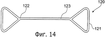
На фиг.14 показана балка с полыми полками Dogbone (зарегистрированный товарный знак), описанная в американском патенте 5163225.On Fig shows a beam with hollow shelves Dogbone (registered trademark), described in US patent 5163225.
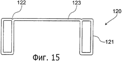
На фиг.15 показана балка с полыми прямоугольными полками, описанная в другой рассматриваемой в настоящее время австралийской заявке 2003903142 данного заявителя.On Fig shows a beam with hollow rectangular shelves, described in another pending Australian application 2003903142 of this applicant.
На фиг.16 показана балка с полыми прямоугольными полками, предназначенная для использования в качестве хорд композитной балочной фермы. Заявленные способ сварки и аппарат особо предпочтительны в том случае, когда секции имеют глубокие или узкие каналы (показаны на чертежах). Иначе, если каналы были образованы с внутренней стороны стенки, было бы трудно приварить свободный край полой полки к поверхности лежащей между краями стенки, из-за невозможности контролировать глубину свободных краев в канале посредством шовнаправляющих роликов. Образование полых полок снаружи стенки сильно упрощает процесс сварки, благодаря точному контролю краев полки.On Fig shows a beam with hollow rectangular shelves, intended for use as chords of a composite beam truss. The claimed welding method and apparatus are particularly preferred when the sections have deep or narrow channels (shown in the drawings). Otherwise, if the channels were formed on the inner side of the wall, it would be difficult to weld the free edge of the hollow shelf to the surface lying between the edges of the wall, due to the inability to control the depth of the free edges in the channel using suture guide rollers. The formation of hollow shelves outside the wall greatly simplifies the welding process, thanks to precise control of the edges of the shelves.
Для специалиста данной области техники очевидно, что в данное изобретение могут быть внесены различные видоизменения, не выходящие за рамки его притязаний и не меняющие его сущность.For a person skilled in the art it is obvious that various modifications can be made to this invention that do not go beyond the scope of its claims and do not change its essence.
Например, формующие ролики, шовнаправляющие ролики и прижимные ролики могут быть сконфигурированы с возможностью обеспечения различных углов касания между свободным краем полой полки и сварным швом, в результате чего при последующем формовании полой полки, для придания ей желаемого сечения, полка испытывает лишь небольшую нагрузку на сварочный шов или вообще не испытывает никакой нагрузки, способной вызвать ее разрушение.For example, forming rollers, seam guide rollers and pinch rollers can be configured to provide different contact angles between the free edge of the hollow shelf and the weld, as a result of which, during subsequent molding of the hollow shelf, in order to give it the desired cross section, the shelf experiences only a small load on the welding the seam or does not experience any load that can cause its destruction.
Claims (20)
образование из металлической полосы профильной поверхности, имеющей свободный край, с получением внутренней полости;
приваривание контактной сваркой сопротивлением или индукционной сваркой указанного свободного края к поверхности этой металлической полосы с образованием полой полки, проходящей вдоль стенки, отличающийся тем, что указанный свободный край нагревают и линейно выравнивают вдоль заданной линии сплавления на указанной поверхности полосы, затем направляют этот свободный край по заданной прямолинейной траектории приближения его к результирующему сварному соединению между указанным свободным краем и указанной поверхностью, при этом энергию сварки фокусируют за счет эффекта их близости по указанной заданной линии сплавления на указанной поверхности до приваривания указанного свободного края.1. A method of manufacturing by welding steel structural elements with hollow shelves in one line on a cold rolling mill, comprising the following steps:
the formation of a metal strip profile surface having a free edge, with the receipt of the inner cavity;
resistance welding or induction welding of the indicated free edge to the surface of this metal strip to form a hollow shelf extending along the wall, characterized in that said free edge is heated and linearly aligned along a predetermined fusion line on the specified surface of the strip, then this free edge is guided along of a given rectilinear trajectory of its approximation to the resulting welded joint between the specified free edge and the specified surface, while Gia welding focus due to the effect of the proximity of said predetermined weld line on said surface prior to welding of said free edge.
по меньшей мере одну клеть шовонаправляющих роликов, содержащую установленный с возможностью вращения по меньшей мере один шовонаправляющий ролик, выполненный с возможностью линейного выравнивания свободного края профильной поверхности металлической полосы вдоль заданной линии сплавления, расположенной на поверхности указанной металлической полосы на расстоянии от указанного свободного края;
клеть сварочной камеры, содержащую установленную с возможностью вращения по меньшей мере одну пару прижимных роликов, предназначенных для направления указанного свободного края, нагретого до заданной температуры, в зону сварки по указанной линии сплавления на указанной поверхности металлической полосы, причем указанная пара прижимных роликов при использовании имеет возможность совместного направления указанного свободного края металлической полосы по заданной прямолинейной траектории по существу по линии приближения к результирующему сварному соединению между указанным свободным краем и указанной поверхностью металлической полосы, при этом энергия сварки фокусируется за счет эффекта их близости по указанной заданной линии сплавления на указанной поверхности.10. Apparatus for the manufacture of steel structural elements with hollow shelves in one line on a cold rolling mill by resistance resistance welding or induction welding, comprising:
at least one stand of the seam guide rollers comprising at least one seam guide roller rotatably arranged to linearly align the free edge of the profile surface of the metal strip along a predetermined fusion line located on the surface of said metal strip at a distance from said free edge;
a welding chamber cage comprising at least one pair of pinch rollers mounted rotatably for directing said free edge heated to a predetermined temperature to the weld zone along said fusion line on said metal strip surface, said pair of pinch rollers being used the possibility of jointly directing the indicated free edge of the metal strip along a given rectilinear path essentially along the line of approximation to the result welding joint between the indicated free edge and the indicated surface of the metal strip, while the welding energy is focused due to the effect of their proximity along the specified predetermined fusion line on the specified surface.
Applications Claiming Priority (2)
| Application Number | Priority Date | Filing Date | Title |
|---|---|---|---|
| AU2004903388 | 2004-06-23 | ||
| AU2004903388A AU2004903388A0 (en) | 2004-06-23 | Improvements in welding hollow flange members |
Publications (2)
| Publication Number | Publication Date |
|---|---|
| RU2006143836A RU2006143836A (en) | 2008-07-27 |
| RU2379166C2 true RU2379166C2 (en) | 2010-01-20 |
Family
ID=35781495
Family Applications (1)
| Application Number | Title | Priority Date | Filing Date |
|---|---|---|---|
| RU2006143836/02A RU2379166C2 (en) | 2004-06-23 | 2005-06-22 | Improvements in welding of structural elements with hollow flanges |
Country Status (20)
| Country | Link |
|---|---|
| US (1) | US20080290140A1 (en) |
| EP (1) | EP1758694B1 (en) |
| JP (1) | JP4473307B2 (en) |
| KR (1) | KR20070030229A (en) |
| CN (1) | CN100484656C (en) |
| AT (1) | ATE519549T1 (en) |
| AU (1) | AU2005256139B2 (en) |
| BR (1) | BRPI0512010A (en) |
| CA (1) | CA2571192A1 (en) |
| DK (1) | DK1758694T3 (en) |
| ES (1) | ES2373961T3 (en) |
| HK (1) | HK1096337A1 (en) |
| IL (1) | IL179965A (en) |
| MX (1) | MXPA06014947A (en) |
| NO (1) | NO20065869L (en) |
| NZ (1) | NZ551940A (en) |
| RU (1) | RU2379166C2 (en) |
| TW (1) | TWI329540B (en) |
| WO (1) | WO2006000018A1 (en) |
| ZA (1) | ZA200700215B (en) |
Families Citing this family (6)
| Publication number | Priority date | Publication date | Assignee | Title |
|---|---|---|---|---|
| RU2371271C2 (en) | 2004-06-23 | 2009-10-27 | Сморгон Стил Лайтстил Продактс Пти Лтд | Device for cold rolling |
| US9097012B2 (en) | 2012-08-08 | 2015-08-04 | Krip Llc | Fabrication member |
| US20140041230A1 (en) | 2012-08-08 | 2014-02-13 | Krip Llc | Fabrication member |
| RU2564183C1 (en) * | 2014-03-20 | 2015-09-27 | Общество с ограниченной ответственностью "Хекса" | Device to round edges of double-tee |
| CN105127264B (en) * | 2015-08-05 | 2017-07-18 | 武铭旗 | A kind of special folding brake of electro-tricycle |
| CN114192955B (en) * | 2021-12-23 | 2022-08-12 | 江苏兆铝金属制品有限公司 | Aluminum profile welding equipment |
Family Cites Families (7)
| Publication number | Priority date | Publication date | Assignee | Title |
|---|---|---|---|---|
| US3391267A (en) * | 1964-08-04 | 1968-07-02 | American Mach & Foundry | Manufacture of welded beams |
| FR2290985A1 (en) * | 1974-11-12 | 1976-06-11 | Metal Deploye | Electric resistance pressure wlding of grids - made from bars and beams with pronounced difference in cross-section |
| NZ230060A (en) * | 1988-07-27 | 1992-06-25 | Tube Technology Pty Ltd | Metal structural beam; edge sections of flat strip rolled and welded to intermediate web to form hollow flanges |
| KR100241640B1 (en) * | 1990-09-28 | 2000-03-02 | 데이비드 골비 레슬리 | Continuous Forming Method of Structural Member |
| EP1260284A3 (en) * | 2001-05-21 | 2004-03-03 | Mitsubishi Shindoh Co., Ltd. | Welded tube manufacturing apparatus and welded tube internal surface bead cutting apparatus |
| JP3700631B2 (en) * | 2001-09-25 | 2005-09-28 | 日産自動車株式会社 | Body part temporary assembly apparatus and body part assembly method |
| ZA200510240B (en) * | 2003-06-23 | 2007-03-28 | Smorgon Steel Litesteel Prod | An improved beam |
-
2005
- 2005-06-22 AT AT05752331T patent/ATE519549T1/en not_active IP Right Cessation
- 2005-06-22 EP EP05752331A patent/EP1758694B1/en not_active Not-in-force
- 2005-06-22 CN CNB2005800209552A patent/CN100484656C/en not_active Expired - Fee Related
- 2005-06-22 AU AU2005256139A patent/AU2005256139B2/en not_active Ceased
- 2005-06-22 MX MXPA06014947A patent/MXPA06014947A/en active IP Right Grant
- 2005-06-22 KR KR1020067027194A patent/KR20070030229A/en not_active Application Discontinuation
- 2005-06-22 DK DK05752331.8T patent/DK1758694T3/en active
- 2005-06-22 WO PCT/AU2005/000897 patent/WO2006000018A1/en active Application Filing
- 2005-06-22 CA CA002571192A patent/CA2571192A1/en not_active Abandoned
- 2005-06-22 RU RU2006143836/02A patent/RU2379166C2/en not_active IP Right Cessation
- 2005-06-22 BR BRPI0512010-1A patent/BRPI0512010A/en not_active IP Right Cessation
- 2005-06-22 ZA ZA200700215A patent/ZA200700215B/en unknown
- 2005-06-22 ES ES05752331T patent/ES2373961T3/en active Active
- 2005-06-22 NZ NZ551940A patent/NZ551940A/en not_active IP Right Cessation
- 2005-06-22 US US11/570,942 patent/US20080290140A1/en not_active Abandoned
- 2005-06-22 JP JP2007516890A patent/JP4473307B2/en active Active
- 2005-06-23 TW TW094121026A patent/TWI329540B/en not_active IP Right Cessation
-
2006
- 2006-12-11 IL IL179965A patent/IL179965A/en not_active IP Right Cessation
- 2006-12-19 NO NO20065869A patent/NO20065869L/en not_active Application Discontinuation
-
2007
- 2007-04-13 HK HK07103871.1A patent/HK1096337A1/en not_active IP Right Cessation
Also Published As
| Publication number | Publication date |
|---|---|
| ATE519549T1 (en) | 2011-08-15 |
| IL179965A (en) | 2012-05-31 |
| EP1758694A1 (en) | 2007-03-07 |
| EP1758694B1 (en) | 2011-08-10 |
| NO20065869L (en) | 2007-03-21 |
| CN101005906A (en) | 2007-07-25 |
| US20080290140A1 (en) | 2008-11-27 |
| KR20070030229A (en) | 2007-03-15 |
| CA2571192A1 (en) | 2006-01-05 |
| MXPA06014947A (en) | 2007-03-23 |
| NZ551940A (en) | 2010-01-29 |
| DK1758694T3 (en) | 2011-11-28 |
| EP1758694A4 (en) | 2007-09-19 |
| AU2005256139A1 (en) | 2006-01-05 |
| TW200618883A (en) | 2006-06-16 |
| ES2373961T3 (en) | 2012-02-10 |
| WO2006000018A1 (en) | 2006-01-05 |
| JP2008503348A (en) | 2008-02-07 |
| RU2006143836A (en) | 2008-07-27 |
| JP4473307B2 (en) | 2010-06-02 |
| HK1096337A1 (en) | 2007-06-01 |
| IL179965A0 (en) | 2007-05-15 |
| CN100484656C (en) | 2009-05-06 |
| BRPI0512010A (en) | 2008-02-06 |
| AU2005256139B2 (en) | 2010-02-25 |
| TWI329540B (en) | 2010-09-01 |
| ZA200700215B (en) | 2008-06-25 |
Similar Documents
| Publication | Publication Date | Title |
|---|---|---|
| RU2371271C2 (en) | Device for cold rolling | |
| EP0566834B1 (en) | Tube production machine | |
| RU2379166C2 (en) | Improvements in welding of structural elements with hollow flanges | |
| JPH06501424A (en) | Multi-component structural member | |
| US4377732A (en) | Method of and apparatus for the production of profile members and hollow bodies from a plurality of metal strips of constant thickness | |
| US3588426A (en) | Method and apparatus for hi-frequency welding edges advanced in parallel | |
| WO2007055405A1 (en) | Method of producing seam-welded pipe having good welded portion characteristics | |
| JP3052555B2 (en) | Manufacturing method of small-diameter ERW pipe | |
| JP3853694B2 (en) | Double pipe manufacturing method and double pipe | |
| JPS6390302A (en) | Steel strip joining device for hot rolling equipment | |
| JP3556061B2 (en) | Open pipe edge preheating device | |
| KR100293577B1 (en) | Method of and apparatus for producing steel pipes | |
| JP2871404B2 (en) | Composite heat source welding pipe making method | |
| JP3052547B2 (en) | ERW pipe manufacturing equipment | |
| US3548141A (en) | Method and apparatus for forming tubing | |
| JPH1177148A (en) | Manufacturing equipment line for steel tube | |
| JP2643472B2 (en) | Manufacturing method of welding heat transfer tube | |
| JPH07204863A (en) | Manufacture of resistance welded tube | |
| JPS62134181A (en) | Heat input controlling method for high frequency seam welding jointly using laser beam | |
| JP2005169455A (en) | Manufacturing apparatus for electric resistance welded tube | |
| JPH06154850A (en) | Production of square electric resistance welded tube | |
| JP2000288626A (en) | Device and method for manufacturing electric resistance welded tube | |
| JPS643568B2 (en) | ||
| JP2002273508A (en) | Method and device for rolling metal plate | |
| JPH10314835A (en) | Pushing-up roll and manufacture of welded tube using the same |
Legal Events
| Date | Code | Title | Description |
|---|---|---|---|
| MM4A | The patent is invalid due to non-payment of fees |
Effective date: 20120623 |