RU2377444C2 - Circulation pump for heating and/or conditioning systems, method for determining parametre typical for such system, and system itself - Google Patents
Circulation pump for heating and/or conditioning systems, method for determining parametre typical for such system, and system itself Download PDFInfo
- Publication number
- RU2377444C2 RU2377444C2 RU2005102765/06A RU2005102765A RU2377444C2 RU 2377444 C2 RU2377444 C2 RU 2377444C2 RU 2005102765/06 A RU2005102765/06 A RU 2005102765/06A RU 2005102765 A RU2005102765 A RU 2005102765A RU 2377444 C2 RU2377444 C2 RU 2377444C2
- Authority
- RU
- Russia
- Prior art keywords
- pump
- working fluid
- hydraulic circuit
- variable
- flow rate
- Prior art date
Links
- 238000010438 heat treatment Methods 0.000 title claims abstract description 17
- 238000000034 method Methods 0.000 title claims abstract description 15
- 230000003750 conditioning effect Effects 0.000 title claims abstract description 6
- 239000012530 fluid Substances 0.000 claims abstract description 44
- 239000012535 impurity Substances 0.000 claims abstract description 28
- 230000008859 change Effects 0.000 claims abstract description 14
- 238000005259 measurement Methods 0.000 claims abstract description 12
- 230000008014 freezing Effects 0.000 claims abstract description 9
- 238000007710 freezing Methods 0.000 claims abstract description 9
- 230000001360 synchronised effect Effects 0.000 claims description 18
- 230000005291 magnetic effect Effects 0.000 claims description 14
- 230000004907 flux Effects 0.000 claims description 12
- 230000006698 induction Effects 0.000 claims description 6
- 230000010363 phase shift Effects 0.000 claims description 4
- 239000003302 ferromagnetic material Substances 0.000 claims description 3
- 230000002301 combined effect Effects 0.000 claims description 2
- 239000000126 substance Substances 0.000 abstract 1
- 239000007788 liquid Substances 0.000 description 8
- LYCAIKOWRPUZTN-UHFFFAOYSA-N Ethylene glycol Chemical compound OCCO LYCAIKOWRPUZTN-UHFFFAOYSA-N 0.000 description 6
- 230000008901 benefit Effects 0.000 description 5
- 230000007423 decrease Effects 0.000 description 5
- 238000004804 winding Methods 0.000 description 5
- 238000004378 air conditioning Methods 0.000 description 4
- 238000004519 manufacturing process Methods 0.000 description 3
- 238000012546 transfer Methods 0.000 description 3
- 230000033228 biological regulation Effects 0.000 description 2
- 238000006243 chemical reaction Methods 0.000 description 2
- 238000013461 design Methods 0.000 description 2
- 238000010586 diagram Methods 0.000 description 2
- 238000012545 processing Methods 0.000 description 2
- 238000010521 absorption reaction Methods 0.000 description 1
- 230000004913 activation Effects 0.000 description 1
- 230000001174 ascending effect Effects 0.000 description 1
- 238000005094 computer simulation Methods 0.000 description 1
- 238000010276 construction Methods 0.000 description 1
- 238000012937 correction Methods 0.000 description 1
- 230000005347 demagnetization Effects 0.000 description 1
- 230000005672 electromagnetic field Effects 0.000 description 1
- 230000005284 excitation Effects 0.000 description 1
- 238000000691 measurement method Methods 0.000 description 1
- 238000012986 modification Methods 0.000 description 1
- 230000004048 modification Effects 0.000 description 1
- 230000000630 rising effect Effects 0.000 description 1
- 238000000926 separation method Methods 0.000 description 1
- XLYOFNOQVPJJNP-UHFFFAOYSA-N water Substances O XLYOFNOQVPJJNP-UHFFFAOYSA-N 0.000 description 1
Images


Classifications
-
- F—MECHANICAL ENGINEERING; LIGHTING; HEATING; WEAPONS; BLASTING
- F24—HEATING; RANGES; VENTILATING
- F24D—DOMESTIC- OR SPACE-HEATING SYSTEMS, e.g. CENTRAL HEATING SYSTEMS; DOMESTIC HOT-WATER SUPPLY SYSTEMS; ELEMENTS OR COMPONENTS THEREFOR
- F24D19/00—Details
- F24D19/0092—Devices for preventing or removing corrosion, slime or scale
-
- F—MECHANICAL ENGINEERING; LIGHTING; HEATING; WEAPONS; BLASTING
- F04—POSITIVE - DISPLACEMENT MACHINES FOR LIQUIDS; PUMPS FOR LIQUIDS OR ELASTIC FLUIDS
- F04D—NON-POSITIVE-DISPLACEMENT PUMPS
- F04D13/00—Pumping installations or systems
- F04D13/02—Units comprising pumps and their driving means
- F04D13/06—Units comprising pumps and their driving means the pump being electrically driven
-
- F—MECHANICAL ENGINEERING; LIGHTING; HEATING; WEAPONS; BLASTING
- F04—POSITIVE - DISPLACEMENT MACHINES FOR LIQUIDS; PUMPS FOR LIQUIDS OR ELASTIC FLUIDS
- F04B—POSITIVE-DISPLACEMENT MACHINES FOR LIQUIDS; PUMPS
- F04B2203/00—Motor parameters
- F04B2203/02—Motor parameters of rotating electric motors
- F04B2203/0203—Magnetic flux
-
- Y—GENERAL TAGGING OF NEW TECHNOLOGICAL DEVELOPMENTS; GENERAL TAGGING OF CROSS-SECTIONAL TECHNOLOGIES SPANNING OVER SEVERAL SECTIONS OF THE IPC; TECHNICAL SUBJECTS COVERED BY FORMER USPC CROSS-REFERENCE ART COLLECTIONS [XRACs] AND DIGESTS
- Y02—TECHNOLOGIES OR APPLICATIONS FOR MITIGATION OR ADAPTATION AGAINST CLIMATE CHANGE
- Y02B—CLIMATE CHANGE MITIGATION TECHNOLOGIES RELATED TO BUILDINGS, e.g. HOUSING, HOUSE APPLIANCES OR RELATED END-USER APPLICATIONS
- Y02B30/00—Energy efficient heating, ventilation or air conditioning [HVAC]
- Y02B30/70—Efficient control or regulation technologies, e.g. for control of refrigerant flow, motor or heating
Abstract
Description
Область применения изобретенияThe scope of the invention
Настоящее изобретение в целом относится к циркуляционному насосу для рабочей жидкости, например к насосу, устанавливаемому в системе отопления и/или кондиционирования.The present invention generally relates to a circulating pump for a working fluid, for example, to a pump installed in a heating and / or air conditioning system.
Изобретение также относится к способу измерения параметра, который является характерным для этой системы, при этом последующее описание относится к указанной области применения и призвано упростить объяснение сущности изобретения.The invention also relates to a method for measuring a parameter that is characteristic of this system, the following description relates to the specified scope and is intended to simplify the explanation of the invention.
Уровень техникиState of the art
Специалистам в данной области техники хорошо известно, что в циркуляционных насосах для рабочей жидкости, устанавливаемых в системах отопления и/или кондиционирования и обычно называемых циркуляторами, как правило, используются электродвигатели асинхронного типа с обмоткой и фазовой подстройкой.Those skilled in the art are well aware that as a rule, asynchronous electric motors with winding and phase adjustment are used in circulating pumps for working fluids installed in heating and / or air conditioning systems and usually called circulators.
Скорость таких насосов регулируют с помощью блока управления на основе мгновенных значений, которые принимают переменные, измеряемые во всей системе установленными в ней датчиками, в частности датчиками расхода, температуры и давления циркулирующей жидкости.The speed of such pumps is controlled by the control unit on the basis of instantaneous values, which take the variables measured in the entire system by the sensors installed in it, in particular, flow, temperature and pressure sensors of the circulating liquid.
Например, для асинхронных двигателей, обычно используемых при изготовлении циркуляторов, необходимо наличие соответствующей силовой электронной схемы для приведения в действие двигателя и регулирования режимов его работы, а также сигнальной электронной схемы для определения, например, скорости вращения двигателя или его фазы.For example, for induction motors, usually used in the manufacture of circulators, it is necessary to have an appropriate power electronic circuit to drive the motor and control its operating modes, as well as a signal electronic circuit to determine, for example, the rotation speed of the motor or its phase.
Несмотря на то, что циркуляторы, в которых используются асинхронные электродвигатели, имеют различные преимущества, им также свойственны известные недостатки, основные из которых перечислены ниже:Despite the fact that circulators that use asynchronous motors have various advantages, they also have known disadvantages, the main of which are listed below:
- недостаточная точность при изменении скорости из-за наличия обмотки и фазовой подстройки, и это создает вибрацию, вызывающую как акустические, так и электрические шумы;- insufficient accuracy when the speed changes due to the presence of the winding and phase adjustment, and this creates a vibration that causes both acoustic and electrical noise;
- невысокий уровень надежности работы циркулятора, так как он зависит от корректной работы расположенных в системе датчиков.- low level of reliability of the circulator, as it depends on the correct operation of the sensors located in the system.
Только в последние годы циркуляторы с установленными в них синхронными электродвигателями, имеющими ротор с постоянными магнитами, начали завоевывать успех на рынке.Only in recent years, circulators with synchronous electric motors installed in them, having a rotor with permanent magnets, began to gain success in the market.
Синхронные двигатели имеют преимущества, заключающиеся в простоте конструкции и сборки, а также в умеренной стоимости.Synchronous motors have the advantages of simplicity of construction and assembly, as well as moderate cost.
Использование синхронных двигателей подразумевает решение некоторых проблем, связанных с приведением их в действие и вызванных тем, что для соответствующего регулирования скорости и изменений направления вращения двигателя магнитный поток возбуждения, являющийся постоянным благодаря постоянным магнитам, требует относительно высокого токопоглощения обмоткой статора.The use of synchronous motors implies the solution of some problems associated with their activation and caused by the fact that for the appropriate regulation of the speed and changes in the direction of rotation of the motor, the magnetic field flux, which is constant due to permanent magnets, requires a relatively high current absorption by the stator winding.
Кроме того, для ограничения тока в одном витке с обеспечением предотвращения риска размагничивания необходимо дальнейшее деление полюсов статора.In addition, to limit the current in one turn while ensuring the risk of demagnetization is prevented, further stator pole separation is necessary.
Эти особенности синхронного двигателя требуют при его управлении применения некоторых приемов, в особенности в тех случаях, когда может произойти внезапное или постепенное изменение нагрузки.These features of a synchronous motor require certain techniques to be used when controlling it, especially in cases where a sudden or gradual change in load can occur.
Это свойственно, например, системе отопления и/или кондиционирования, выполненной с замкнутым гидравлическим контуром, в котором протекает жидкость, содержащая незамерзающие примеси, которые могут присутствовать в существенном количестве. Это часто бывает, когда система должна работать в условиях сильных холодов, например в северных странах.This is characteristic, for example, of a heating and / or air conditioning system made with a closed hydraulic circuit in which a fluid flows containing non-freezing impurities that may be present in significant quantities. This often happens when the system must operate in severe cold conditions, for example in northern countries.
В связи с этим существует потребность в периодической проверке хорошей работы системы, чтобы в случае необходимости можно было добавить незамерзающие примеси или отрегулировать расход рабочей жидкости в соответствии с потребностью в тепле, которая является функцией от внутренней и/или внешней температуры.In this regard, there is a need to periodically check the good operation of the system so that, if necessary, it is possible to add non-freezing impurities or adjust the flow rate of the working fluid in accordance with the need for heat, which is a function of internal and / or external temperature.
В US 2002/0192085 раскрыта система жидкостной циркуляции, содержащая первый и второй гидравлические контуры. Циркуляционный насос в этой системе подает рабочую жидкость и дозированные примеси. Однако этот насос не имеет привода от синхронного электродвигателя с электронным управлением. Насос для дозированной подачи примесей (определенного количества жидкости), имеющий привод от синхронного электродвигателя, известен из US 4702674. Однако в этом документе не раскрывается порядок определения состояния рабочей системы и соответствующего регулирования ее работы.US 2002/0192085 discloses a fluid circulation system comprising first and second hydraulic circuits. The circulation pump in this system supplies the working fluid and dosed impurities. However, this pump is not driven by an electronically controlled synchronous motor. A pump for the dosed supply of impurities (a certain amount of liquid), driven by a synchronous electric motor, is known from US 4702674. However, this document does not disclose the procedure for determining the state of the working system and the corresponding regulation of its operation.
В основе настоящего изобретения лежит техническая проблема, заключающаяся в создании циркуляционного насоса для рабочей жидкости, устанавливаемого в системе отопления и/или кондиционирования и имеющего такие конструкцию и рабочие характеристики, которые позволяют предоставлять информацию о состоянии этой системы путем определения например, процентного содержания примеси в рабочей жидкости системы и тем самым позволяют регулировать режим работы системы.The present invention is based on a technical problem, which consists in creating a circulation pump for a working fluid installed in a heating and / or air conditioning system and having such a design and performance that allow providing information about the state of this system by determining, for example, the percentage of impurities in the working fluid system and thereby allow you to adjust the mode of operation of the system.
Сущность изобретенияSUMMARY OF THE INVENTION
Решение поставленной проблемы в соответствии с изобретением обеспечено путем создания циркуляционного насоса для рабочей жидкости описанного выше типа и отличающегося тем, что он содержит выход сигнала из управляющей электронной схемы для получения величины, соответствующей процентному содержанию примеси в рабочей жидкости системы.The solution of the problem in accordance with the invention is provided by creating a circulation pump for the working fluid of the type described above and characterized in that it contains a signal output from the control electronic circuit to obtain a value corresponding to the percentage of impurities in the working fluid of the system.
Изобретение также относится к способу измерения параметра, который является характерным для системы отопления, как указано в пункте 4 формулы изобретения.The invention also relates to a method for measuring a parameter that is characteristic of a heating system, as indicated in paragraph 4 of the claims.
Дополнительные характеристики и преимущества предложенных циркуляционного насоса и способа измерения вытекают из нижеследующего описания варианта выполнения изобретения, приведенного со ссылками на приложенные чертежи и являющегося иллюстративным примером, не ограничивающим объема изобретения.Additional characteristics and advantages of the proposed circulation pump and measurement method result from the following description of an embodiment of the invention, given with reference to the attached drawings and which is an illustrative example, not limiting the scope of the invention.
Краткое описание чертежейBrief Description of the Drawings
Фиг.1 изображает схему системы отопления, в которой установлен циркуляционный насос, выполненный в соответствии с изобретением;Figure 1 depicts a diagram of a heating system in which a circulation pump, made in accordance with the invention;
фиг.2 схематично изображает синхронный электродвигатель для приведения в действие насоса, который показан на фиг.1 и который в соответствии с изобретением содержит средства определения процентного содержания примеси в рабочей жидкости системы;figure 2 schematically depicts a synchronous motor for driving a pump, which is shown in figure 1 and which in accordance with the invention contains means for determining the percentage of impurities in the working fluid of the system;
фиг.3 изображает блок-схему электронного управляющего устройства для управления работой насоса; иfigure 3 depicts a block diagram of an electronic control device for controlling the operation of the pump; and
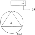
фиг.4 схематично изображает предложенный насос с электронным управляющим устройством.figure 4 schematically depicts the proposed pump with an electronic control device.
Подробное описание предпочтительного варианта выполненияDetailed Description of a Preferred Embodiment
На чертежах в целом представлена система 1 отопления и/или кондиционирования, которая имеет циркуляционный насос 2 для рабочей жидкости, выполненный в соответствии с настоящим изобретением.The drawings generally show a heating and / or conditioning system 1, which has a circulating pump 2 for a working fluid, made in accordance with the present invention.
Преимущественно насос 2 является синхронным, то есть он приводится во вращение синхронным электродвигателем 12, содержащим ротор 14 с постоянными магнитами. Внутренняя конструкция электродвигателя 12 для приведения в действие насоса, представленная на фиг.2, описана ниже.Advantageously, the pump 2 is synchronous, that is, it is driven by a synchronous
Система 1 содержит замкнутый гидравлический контур 6, который ниже называется главным и который включает нагревательные элементы 7.The system 1 contains a closed hydraulic circuit 6, which is called the main below and which includes heating elements 7.
Контур 6 последовательно содержит синхронный насос 2, главный теплообменник 3, а именно бойлер, и нагревательные элементы 7.Circuit 6 sequentially comprises a synchronous pump 2, a main heat exchanger 3, namely a boiler, and heating elements 7.
Параллельно части контура, где расположены нагревательные элементы 7, расположен дополнительный теплообменник 5, который подает тепло в сантехнический контур 9, например в контур подачи горячей воды для бытовых нужд. Теплообменник 5 является частью дополнительного замкнутого гидравлического контура 8.Parallel to the part of the circuit where the heating elements 7 are located, an additional heat exchanger 5 is located, which supplies heat to the sanitary circuit 9, for example, to the domestic hot water supply circuit. The heat exchanger 5 is part of an additional closed hydraulic circuit 8.
В соединительном узле, который расположен между главным 6 и дополнительным 8 контурами и от которого ответвляются участки трубопровода, параллельные участку контура, в котором расположены элементы 7, расположен трехходовой клапан 4 с сервоприводом.In the connecting node, which is located between the main 6 and additional 8 circuits and from which branches of the pipeline parallel to the circuit section in which the elements 7 are located, there is a three-way valve 4 with a servomotor.
В соответствии с изобретением процентное содержание незамерзающих примесей можно определять преимущественно на основе определения гидродинамических параметров жидкости, проходящей через насос 2.In accordance with the invention, the percentage of non-freezing impurities can be determined mainly on the basis of determining the hydrodynamic parameters of the fluid passing through the pump 2.
Другими словами, насос 2 обеспечивает возможность создания электрических сигналов, соответствующих процентному содержанию примесей в системе.In other words, the pump 2 provides the ability to create electrical signals corresponding to the percentage of impurities in the system.
В частности, на фиг.3 показано электронное управляющее устройство 10, выполненное в соответствии с настоящим изобретением, предназначенное для определения процентного содержания незамерзающих примесей в рабочей жидкости системы 1.In particular, figure 3 shows an
Устройство 10 также выполнено с возможностью определения расхода рабочего тела в насосе 2, приводимом в действие синхронным электродвигателем 12. Показанный на фиг.3 электродвигатель 12 содержит ротор 14 с постоянным магнитом, приводимый во вращение электромагнитным полем, создаваемым статором 16, имеющим полюсные башмаки 18 с соответствующими обмотками.The
Устройство 10 содержит датчик 20 магнитного потока ротора 14, например датчик Холла, расположенный на статоре 16 вблизи ротора 14. Датчик 20 соединен с процессорным блоком 22, выполненным, например, в виде контроллера или центрального процессора и выводящим величину расхода в насосе.The
В соответствии с настоящим изобретением для определения расхода Q в насосе, приводимом в действие электродвигателем 12, используется блок 22 устройства 10, с которым связано запоминающее устройство для хранения экспериментальных данных о соотношении между величинами расхода и соответствующими значениями рабочей переменной электродвигателя насоса, например угла нагрузки.In accordance with the present invention, to determine the flow rate Q in the pump driven by the
На практике в соответствии с изобретением можно определять расход Q потока жидкости, циркулирующей в насосе 2, приводимом в действие электродвигателем 12, во время его работы в установившемся режиме, измеряя рабочую переменную насоса, в частности измеряя угол ![]()
![]()
Хорошо известно, что угол ![]()
![]()
При изменении нагрузки, приложенной к оси насоса, соединенного с электродвигателем 12, также изменяется момент сопротивления, приложенный к ротору 14 электродвигателя 12. Тем самым изменяется угол сдвига между противодействующей электродвижущей силой и напряжением в сети, который и является углом ![]()
![]()
Увеличение угла нагрузки пропорционально увеличению расхода Q в насосе, и эта пропорциональность на некоторых интервалах является прямой. Например, при линеаризации этого соотношения увеличение расхода предполагает пропорциональное увеличение угла нагрузки, и наоборот, уменьшение расхода соответствует уменьшению угла нагрузки.An increase in the load angle is proportional to an increase in the flow rate Q in the pump, and this proportionality at some intervals is direct. For example, when linearizing this ratio, an increase in flow rate implies a proportional increase in the load angle, and vice versa, a decrease in flow rate corresponds to a decrease in the load angle.
В соответствии с изобретением соотношение между величинами расхода и соответствующими величинами угла нагрузки задается, то есть это соотношение может определяться экспериментальным путем, а также путем теоретического моделирования или компьютерного моделирования, предпочтительно в ходе калибровки, как правило, выполняемой при изготовлении насоса.According to the invention, the ratio between the flow rates and the corresponding values of the load angle is set, that is, this ratio can be determined experimentally, as well as by theoretical modeling or computer simulation, preferably during calibration, as a rule, performed in the manufacture of the pump.
Более подробно, как показано на фиг.3, блок 22, помимо того, что он соединен с датчиком 20, получает также сигнал 24 синхронности сети и сигнал, пропорциональный действующей величине напряжения 26 в сети.In more detail, as shown in FIG. 3,
Если датчик 20 является датчиком Холла, измеряют пик магнитного потока ротора 14. Принимая во внимание, что этот пик отстает от противодействующей электродвижущей силы на 90°, точно определяют угол ![]()
![]()
Таким образом, в блоке 22 определяют фазовый сдвиг ![]()
![]()
Следует отметить, что цифровой датчик 20 Холла выдает сигнал прямоугольной формы, в котором нарастающий фронт и задний фронт совпадают с переменой полярности постоянного магнита ротора 14 во время вращения.It should be noted that the
Время, проходящее между фронтом сигнала 24 и фронтом сигнала датчика 20, который является сигналом положения ротора 14, пропорционально углу ![]()
![]()
Однако это время изменяется в соответствии с расходом, напряжением питания электродвигателя 12 и рабочей температурой магнита ротора 14.However, this time varies in accordance with the flow rate, the voltage of the
В этом случае следует уточнить, что зависимость угла ![]()
![]()
![]()
![]()
Если напряжение в сети уменьшается, также уменьшается интенсивность магнитного потока, создаваемого статором 16, следствием чего является недовозбуждение электродвигателя 12.If the voltage in the network decreases, the intensity of the magnetic flux generated by the
Недовозбуждение электродвигателя 12 затрудняет поддержание в нем состояния синхроннности и воспринимается как увеличение рабочей нагрузки. Прямым следствием этого является увеличение угла нагрузки.The non-excitation of the
И наоборот, увеличение напряжения в сети предполагает перевозбуждение электродвигателя 12 и таким образом уменьшение угла нагрузки.Conversely, increasing the voltage in the network involves over-excitation of the
Таким образом, гидравлический расход Q циркулирующей рабочей жидкости получают исходя из рабочих условий синхронного электродвигателя, предназначенного для приведения в действие насоса 2.Thus, the hydraulic flow rate Q of the circulating working fluid is obtained on the basis of the operating conditions of a synchronous electric motor designed to drive the pump 2.
Температуру рабочей жидкости также можно определять исходя из рабочих условий синхронного электродвигателя, предназначенного для приведения в действие насоса 2.The temperature of the working fluid can also be determined based on the operating conditions of a synchronous electric motor designed to drive the pump 2.
Зависимость от температуры рабочей жидкости обусловлена тем, что ферромагнитный материал, из которого изготовлен ротор 14, имеет остаточную магнитную индукцию BR, которая изменяется в соответствии с температурой.The dependence on the temperature of the working fluid is due to the fact that the ferromagnetic material of which the
Повышение рабочей температуры магнита ротора 14 способствует уменьшению остаточной магнитной индукции ВR, что, в свою очередь, снижает интенсивность связанного с ней магнитного потока, вследствие чего электродвигатель 12 приходит в состояние, аналогичное состоянию, имеющему место при уменьшении напряжения питания.An increase in the operating temperature of the
Таким образом, увеличение температуры вызывает увеличение угла нагрузки и наоборот.Thus, an increase in temperature causes an increase in the load angle and vice versa.
Чтобы определить, чем обусловлено изменение угла ![]()
![]()
Этот сигнал 26 может быть, например, получен из сигнала 30 напряжения в сети с помощью преобразующего блока 28, например схемы преобразования напряжения. Благодаря сигналу 26 блок 22 может вернуться к величине, обеспечивающей эффективную подачу. Таким образом, блок 22 способен выдавать сигнал, пропорциональный гидравлическому расходу и совершенно не зависящий от напряжения питания.This
Далее, чтобы определить, чем обусловлено изменение угла ![]()
![]()
Этот датчик не только обеспечивает возможность слежения за сменой полярности магнита ротора 14, но и может выдавать синусоидальный сигнал, ширина которого пропорциональна остаточной индукции BR ферромагнитного материала, из которого изготовлен ротор 14.This sensor not only provides the ability to track the change in polarity of the magnet of the
Поскольку указанная остаточная индукция BR постоянного магнита напрямую зависит от рабочей температуры, благодаря синусоидальному сигналу, выдаваемому аналоговым датчиком 20А, блок 22 может также отличить изменение угла нагрузки в результате изменения расхода от изменения угла нагрузки в результате изменения температуры.Since the indicated residual induction B R of the permanent magnet directly depends on the operating temperature, due to the sinusoidal signal generated by the
В сущности выходной сигнал 34, соответствующий расходу Q, выдается пропорционально данным измерителя 32 угла ![]()
![]()
По сути благодаря блоку 22 устройства 10 можно получать следующие данные и выполнять следующую обработку электрических сигналов:In fact, thanks to the
- получение текущих значений угла ![]()
![]()
- сравнение текущей величины указанного угла с величинами, хранящимися в заранее заданной таблице корреляции с величинами расхода;- comparing the current value of the specified angle with the values stored in a predetermined correlation table with flow rates;
- возможную поправку величин расхода в соответствии со значениями напряжения в сети и/или температуры магнита ротора и определение текущей величины расхода.- a possible correction of the flow rate in accordance with the values of the voltage in the network and / or the temperature of the rotor magnet and the determination of the current flow rate.
В соответствии с настоящим изобретением можно также определять процентное содержание примеси в рабочей жидкости, циркулирующей в системе 1. Это процентное содержание определяют косвенным путем, начиная с мгновенных рабочих условий электродвигателя 12, предназначенного для приведения в действие насоса 2.In accordance with the present invention, it is also possible to determine the percentage of impurities in the working fluid circulating in the system 1. This percentage is determined indirectly, starting from the instantaneous operating conditions of the
Таким образом, блок 22 может создавать дополнительный выходной сигнал 35, например как показано на фиг.4, для получения величины, соответствующей процентному содержанию примеси в рабочей жидкости.Thus, the
Как указано выше, процентное содержание примеси является особенно важной информацией, так как незамерзающие примеси, как правило, вводят в существенном объеме, например до 40%.As indicated above, the percentage of impurities is particularly important information, since non-freezing impurities, as a rule, are introduced in a substantial volume, for example up to 40%.
Более того, эффективность системы зависит как от теплообменников 3 и 5 контуров 6 и 9, так и от процентного содержания незамерзающих примесей. Фактически, добавление незамерзающих примесей может увеличить вязкость рабочей жидкости на 20%, что явно влияет на энергетическую эффективность системы.Moreover, the efficiency of the system depends both on the heat exchangers 3 and 5 of circuits 6 and 9, and on the percentage of non-freezing impurities. In fact, the addition of non-freezing impurities can increase the viscosity of the working fluid by 20%, which clearly affects the energy efficiency of the system.
Это также означает, что известному процентному содержанию примеси также соответствует заданный энергетический КПД системы 1. Следовательно, зная процентное содержание примеси, можно также с помощью дополнительных средств получать информацию о КПД системы 1.This also means that the predetermined percentage of the impurity also corresponds to a given energy efficiency of the system 1. Therefore, knowing the percentage of the impurity, it is also possible to obtain information on the efficiency of the system 1 using additional means.
Например, ниже приведена таблица, в которой представлена связь между удельной теплоемкостью жидкости при нескольких значениях рабочей температуры и процентным содержанием примеси, в качестве которой используется этиленгликоль.For example, the table below shows the relationship between the specific heat of a liquid at several operating temperatures and the percentage of impurity, which is used as ethylene glycol.
ТаблицаTable
Вязкость циркулирующей рабочей жидкости влияет на потребление электроэнергии синхронным электродвигателем в соответствии с известным соотношением, которое зависит от гидродинамических характеристик насоса 2. Например, можно использовать следующую формулуThe viscosity of the circulating fluid affects the power consumption of the synchronous motor in accordance with a known ratio, which depends on the hydrodynamic characteristics of pump 2. For example, you can use the following formula
m·ξ(1/d)·(ω2/2)=Р,m · ξ (1 / d) · (ω 2/2) = P
где m - массовый расход,where m is the mass flow rate,
ξ - коэффициент трения,ξ is the coefficient of friction,
1 - приведенная длина гидравлического контура,1 - the reduced length of the hydraulic circuit,
d - приведенный диаметр гидравлического контура,d is the reduced diameter of the hydraulic circuit,
ω - скорость электродвигателя циркулятора,ω is the speed of the circulator motor,
Р - потребляемая мощность.P is the power consumption.
Коэффициент ξ трения, зависящий от числа (Re) Рейнольдса, получают экспериментальным путем в гидравлическом контуре. Число Re зависит, в свою очередь, от вязкости µ жидкости в соответствии с соотношениемThe friction coefficient ξ, which depends on the Reynolds number (Re), is obtained experimentally in a hydraulic circuit. The number Re depends, in turn, on the viscosity μ of the liquid in accordance with the relation
Re=1·d·ω/µ.Re = 1 · d · ω / μ.
Кроме того, вязкость µ циркулирующей рабочей жидкости влияет на коэффициенты теплообмена и, таким образом, на теплопроизводительность теплообменников. Так что изменение этой величины относительно известных начальных условий служит показателем вязкости жидкости.In addition, the viscosity µ of the circulating working fluid affects the heat transfer coefficients and, thus, the heat output of the heat exchangers. So a change in this quantity relative to the known initial conditions is an indicator of the viscosity of the liquid.
Для определения величины теплопроизводительности системы 1 при базовых начальных условиях можно использовать начальное измерение, выполненное при закрытой задвижке непосредственно за насосом 2, т.е. при отсутствии подачи рабочей жидкости.To determine the heat output of system 1 under basic initial conditions, you can use the initial measurement made with a closed valve directly behind pump 2, i.e. in the absence of a supply of working fluid.
Затем можно выполнять следующее измерение путем обеспечения циркуляции рабочей жидкости только в дополнительной теплообменнике 5 санитарного контура 9.Then you can perform the following measurement by circulating the working fluid only in the additional heat exchanger 5 of the sanitary circuit 9.
Для этого можно регулировать клапан 4 с обеспечением запитывания только теплообменника 5. При этом насос 2 работает только для запитывания контура 9.To do this, you can adjust the valve 4 to ensure that only the heat exchanger 5 is supplied. In this case, the pump 2 only works to power the circuit 9.
Теплопроизводительность теплообменника 5 зависит от гидродинамических характеристик самого теплообменника и от вязкости жидкости, при этом можно использовать, например, следующую формулуThe heat capacity of the heat exchanger 5 depends on the hydrodynamic characteristics of the heat exchanger itself and on the viscosity of the liquid, while you can use, for example, the following formula
q=αAΔt,q = αAΔt,
где α - результирующий коэффициент конвективного теплообмена,where α is the resulting coefficient of convective heat transfer,
А - приведенная поверхность теплообмена,A - reduced heat transfer surface,
Δt - теплоперепад между впуском и выпуском теплообменника.Δt is the heat difference between the inlet and outlet of the heat exchanger.
Как известно, коэффициент α зависит от числа (Nu) Нуссельта в соответствии со следующим отношениемAs is known, the coefficient α depends on the Nusselt number (Nu) in accordance with the following relation
α=(Nu·λ)/d,α = (Nu · λ) / d,
где λ - теплопроводность,where λ is the thermal conductivity,
d - приведенный гидравлический диаметр.d is the reduced hydraulic diameter.
ДалееFurther
Nu=С·Rem·Рrn,Nu = C · Re m · Pr n ,
где С, m и n - экспериментальные коэффициенты,where C, m and n are experimental coefficients,
Re - число Рейнольдса, и Рr - число Прандтля, которые зависят от рабочих характеристик жидкости, таких как вязкость, удельная теплоемкость и теплопроводность.Re is the Reynolds number, and Pr is the Prandtl number, which depend on the fluid’s performance, such as viscosity, specific heat, and thermal conductivity.
Зная тип используемой примеси, вязкость жидкости и температуру Т, можно получить из экспериментальных таблиц, где приведено соотношение с мощностью, потребляемой насосом при известных условиях работы контура, а именно при закрытой подаче насоса или, например, при циркуляции, ограниченной только дополнительным контуром теплообменника 5.Knowing the type of impurity used, the viscosity of the liquid and the temperature T, it is possible to obtain from the experimental tables, which show the relationship with the power consumed by the pump under known conditions of the circuit, namely, with a closed pump supply or, for example, with circulation limited only by the additional heat exchanger circuit 5 .
Предложенный способ можно также осуществлять с помощью насоса, приводимого в действие асинхронным электродвигателем, имеющим датчики для определения расхода Q рабочей жидкости. Кроме того, в этом случае можно было бы исходя из величины расхода получать сигнал, соответствующий процентному содержанию примеси, с помощью первого измерения при закрытом впуске и последующего измерения в дополнительном гидравлическом контуре.The proposed method can also be carried out using a pump driven by an asynchronous electric motor having sensors for determining the flow rate Q of the working fluid. In addition, in this case, based on the flow rate, it would be possible to obtain a signal corresponding to the percentage of impurity using the first measurement with the inlet closed and the subsequent measurement in the additional hydraulic circuit.
В сущности предложенный способ позволяет получить информацию о процентном содержании примеси путем использования только насоса в системе 1. Очевидно, что использование синхронного насоса имеет дополнительное преимущество, заключающееся в возможности выполнения измерения без датчиков.In fact, the proposed method allows to obtain information on the percentage of impurities by using only a pump in system 1. Obviously, the use of a synchronous pump has the additional advantage of being able to perform measurements without sensors.
Главное преимущество, обеспечиваемое предложенным циркуляционным насосом для жидкости, состоит в реальной возможности получения выходного сигнала, соответствующего величине процентного содержания примеси в рабочей жидкости системы.The main advantage provided by the proposed circulation pump for the liquid is the real possibility of obtaining an output signal corresponding to the percentage of impurities in the working fluid of the system.
И наоборот, значение выходного сигнала, полученного из управляющей схемы для управления насосом, позволяет получать информацию о состоянии КПД системы 1, если известны другие гидродинамические параметры, такие как расход, рабочая температура и процентное содержание примеси.Conversely, the value of the output signal obtained from the control circuit for controlling the pump allows you to obtain information about the efficiency state of system 1 if other hydrodynamic parameters, such as flow rate, operating temperature, and percentage of impurities, are known.
Очевидно, что специалист может произвести некоторые модификации описанного выше циркуляционного насоса, соответствующие конкретным потребностям, в пределах объема правовой охраны настоящего изобретения, ограниченного прилагаемой формулой изобретения.It is obvious that the specialist can make some modifications of the circulating pump described above, corresponding to specific needs, within the scope of legal protection of the present invention, limited by the attached claims.
Claims (11)
начальное измерение расхода циркулирующей рабочей жидкости, которое проводят непосредственно за насосом при отсутствии ее подачи,
последующее измерение расхода циркулирующей рабочей жидкости только в дополнительном гидравлическом контуре (9),
причем указанные первое и второе измерения проводят с помощью средств, связанных с управляющим устройством (10) насоса (2), с обеспечением создания выходного электрического сигнала, соответствующего процентному содержанию примеси в циркулирующей рабочей жидкости или изменению теплопроизводительности системы.4. A method for measuring a parameter characteristic of a heating and / or conditioning system (1), which comprises a main hydraulic circuit (6) and an additional hydraulic circuit (9) and which has at least one circulating pump (2) for the working fluid driven driven by an electric motor and controlled by an electronic control device (10), characterized in that it includes:
initial measurement of the flow rate of the circulating working fluid, which is carried out directly behind the pump in the absence of its supply,
subsequent measurement of the flow rate of the circulating working fluid only in the additional hydraulic circuit (9),
moreover, these first and second measurements are carried out using means associated with the control device (10) of the pump (2), ensuring the creation of an output electrical signal corresponding to the percentage of impurities in the circulating working fluid or a change in the heat output of the system.
получения по меньшей мере одной рабочей переменной насоса, сравнения величины этой переменной с заданной таблицей соотношения со значениями гидравлического расхода и определения соответствующего значения расхода.5. The method according to claim 4, characterized in that the pump (2) is driven by a synchronous electric motor (12) having a rotor (14) with a permanent magnet, and said first and second measurements are carried out by:
obtaining at least one operating variable of the pump, comparing the value of this variable with a given ratio table with the values of the hydraulic flow rate and determining the corresponding flow rate value.
Applications Claiming Priority (2)
| Application Number | Priority Date | Filing Date | Title |
|---|---|---|---|
| EP04425093A EP1564408B1 (en) | 2004-02-12 | 2004-02-12 | Fluid circulation pump for heating and conditioning systems and the like |
| EP04425093.4 | 2004-02-12 |
Publications (2)
| Publication Number | Publication Date |
|---|---|
| RU2005102765A RU2005102765A (en) | 2006-07-10 |
| RU2377444C2 true RU2377444C2 (en) | 2009-12-27 |
Family
ID=34684822
Family Applications (1)
| Application Number | Title | Priority Date | Filing Date |
|---|---|---|---|
| RU2005102765/06A RU2377444C2 (en) | 2004-02-12 | 2005-01-31 | Circulation pump for heating and/or conditioning systems, method for determining parametre typical for such system, and system itself |
Country Status (9)
| Country | Link |
|---|---|
| US (1) | US20050180857A1 (en) |
| EP (1) | EP1564408B1 (en) |
| KR (1) | KR101190989B1 (en) |
| CN (1) | CN100565415C (en) |
| AT (1) | ATE344390T1 (en) |
| DE (1) | DE602004003023T2 (en) |
| DK (1) | DK1564408T3 (en) |
| ES (1) | ES2276260T3 (en) |
| RU (1) | RU2377444C2 (en) |
Cited By (4)
| Publication number | Priority date | Publication date | Assignee | Title |
|---|---|---|---|---|
| RU2546342C2 (en) * | 2010-12-30 | 2015-04-10 | Флюид Хэндлинг ЭлЭлСи. | Method and apparatus for pump control using varying equivalent system characteristic, known as adaptive control curve |
| RU2614349C1 (en) * | 2015-12-10 | 2017-03-24 | Федеральное государственное бюджетное образовательное учреждение высшего образования "Юго-Западный государственный университет" (ЮЗГУ) | Independent circulation thermal electrical pump for heating systems |
| RU2663781C2 (en) * | 2013-11-07 | 2018-08-09 | Грундфос Холдинг А/С | Circulating pump unit for heating and/or cooling system |
| RU2680474C2 (en) * | 2014-04-08 | 2019-02-21 | Флюид Хэндлинг ЭлЭлСи | Device (options) and method for pump differential pressure and flow monitoring |
Families Citing this family (7)
| Publication number | Priority date | Publication date | Assignee | Title |
|---|---|---|---|---|
| EP2224175B1 (en) * | 2009-02-27 | 2017-11-01 | Hauser, Oswald | Control system for controlling thermosolar plants and method |
| EP2708825B1 (en) * | 2012-09-12 | 2016-12-07 | Grundfos Holding A/S | Method for controlling a circulating pump in an assembly with at least two circuits |
| CN105518305B (en) * | 2013-07-25 | 2018-09-14 | 流体处理有限责任公司 | Control is adaptively pumped without sensor with self-calibrating device for liquid circulation pumping system |
| EP2910788B1 (en) | 2014-02-25 | 2018-04-04 | TACO ITALIA S.r.l. | Method for controlling a pumping station within a fluid circulation system, related circulation system and pumping station for realizing said method |
| EP3037670B1 (en) * | 2014-12-22 | 2019-07-31 | Grundfos Holding A/S | Hydraulic system |
| DE202015103940U1 (en) * | 2015-07-28 | 2016-11-02 | Gebr. Kemper Gmbh + Co. Kg Metallwerke | heat exchanger system |
| CN108072088A (en) * | 2016-11-15 | 2018-05-25 | 长春中安鸿程伟业节能科技有限公司 | A kind of central heating secondary network electric heating pump peak regulation system |
Family Cites Families (13)
| Publication number | Priority date | Publication date | Assignee | Title |
|---|---|---|---|---|
| US3493345A (en) * | 1967-12-20 | 1970-02-03 | Du Pont | Method of controlling polymer viscosity during synthesis by utilizing motor load |
| BE790711A (en) * | 1971-11-01 | 1973-04-30 | Westinghouse Electric Corp | TWO MOTOR DRIVE SYSTEM |
| US4731571A (en) * | 1985-03-12 | 1988-03-15 | The United States Of America As Represented By The United States Department Of Energy | Control for stabilizing the alignment position of the rotor of a synchronous motor |
| FR2588319B1 (en) * | 1985-10-04 | 1987-12-04 | Milton Roy Dosapro | PROCESS FOR PRECISELY ESTABLISHING THE FLOW RATE OF A METERING PUMP AND METERING PUMP USING THE SAME |
| JPH01191019A (en) * | 1988-01-26 | 1989-08-01 | Akitoshi Kitano | Instrumental error correcting method for flowmeter |
| DE69526717T2 (en) * | 1995-01-11 | 2003-01-30 | Micropump Inc | System with built-in pump and fluid flow meter |
| IT1291190B1 (en) * | 1997-03-13 | 1998-12-29 | Gate Spa | Cooling system for an internal combustion engine, particularly for motor vehicles |
| US6432566B1 (en) * | 1999-10-25 | 2002-08-13 | Utc Fuel Cells, Llc | Direct antifreeze cooled fuel cell power plant |
| US6497035B1 (en) * | 1999-12-06 | 2002-12-24 | Hr Textron, Inc. | Hall position sensor |
| FR2811381B1 (en) * | 2000-07-06 | 2002-10-25 | Bosatron Internat | DEVICE FOR VARIING THE DOSING OF AN ADDITIVE IN A LIQUID, PUMP AND DOSING SYSTEM EQUIPPED WITH SUCH A DEVICE |
| US6789434B2 (en) * | 2001-10-23 | 2004-09-14 | Dwyer Instruments, Inc. | Fluid flowmeter having a hall effect sensor with an internal magnet |
| EP1351376A1 (en) * | 2002-03-11 | 2003-10-08 | Askoll Holding S.r.l. | Electronic device for starting and controlling a permanent-magnet synchronous motor |
| US6833697B2 (en) * | 2002-09-11 | 2004-12-21 | Honeywell International Inc. | Saturated magnetoresistive approach for linear position sensing |
-
2004
- 2004-02-12 DE DE602004003023T patent/DE602004003023T2/en not_active Expired - Lifetime
- 2004-02-12 ES ES04425093T patent/ES2276260T3/en not_active Expired - Lifetime
- 2004-02-12 DK DK04425093T patent/DK1564408T3/en active
- 2004-02-12 EP EP04425093A patent/EP1564408B1/en not_active Expired - Lifetime
- 2004-02-12 AT AT04425093T patent/ATE344390T1/en not_active IP Right Cessation
-
2005
- 2005-01-31 RU RU2005102765/06A patent/RU2377444C2/en not_active IP Right Cessation
- 2005-02-07 US US11/052,272 patent/US20050180857A1/en not_active Abandoned
- 2005-02-07 KR KR1020050011419A patent/KR101190989B1/en active IP Right Grant
- 2005-02-16 CN CNB2005100094993A patent/CN100565415C/en active Active
Cited By (4)
| Publication number | Priority date | Publication date | Assignee | Title |
|---|---|---|---|---|
| RU2546342C2 (en) * | 2010-12-30 | 2015-04-10 | Флюид Хэндлинг ЭлЭлСи. | Method and apparatus for pump control using varying equivalent system characteristic, known as adaptive control curve |
| RU2663781C2 (en) * | 2013-11-07 | 2018-08-09 | Грундфос Холдинг А/С | Circulating pump unit for heating and/or cooling system |
| RU2680474C2 (en) * | 2014-04-08 | 2019-02-21 | Флюид Хэндлинг ЭлЭлСи | Device (options) and method for pump differential pressure and flow monitoring |
| RU2614349C1 (en) * | 2015-12-10 | 2017-03-24 | Федеральное государственное бюджетное образовательное учреждение высшего образования "Юго-Западный государственный университет" (ЮЗГУ) | Independent circulation thermal electrical pump for heating systems |
Also Published As
| Publication number | Publication date |
|---|---|
| KR20060041846A (en) | 2006-05-12 |
| DK1564408T3 (en) | 2007-03-05 |
| EP1564408A1 (en) | 2005-08-17 |
| ATE344390T1 (en) | 2006-11-15 |
| CN1658108A (en) | 2005-08-24 |
| EP1564408B1 (en) | 2006-11-02 |
| US20050180857A1 (en) | 2005-08-18 |
| KR101190989B1 (en) | 2012-10-16 |
| DE602004003023D1 (en) | 2006-12-14 |
| RU2005102765A (en) | 2006-07-10 |
| CN100565415C (en) | 2009-12-02 |
| DE602004003023T2 (en) | 2007-06-06 |
| ES2276260T3 (en) | 2007-06-16 |
Similar Documents
| Publication | Publication Date | Title |
|---|---|---|
| RU2377444C2 (en) | Circulation pump for heating and/or conditioning systems, method for determining parametre typical for such system, and system itself | |
| US8155915B2 (en) | Method for determining the temperature of the delivery fluid of a centrifugal pump | |
| RU2681390C2 (en) | Sensorless adaptive pump control with self-calibration apparatus for hydronic pumping system | |
| Ahonen et al. | Estimation of pump operational state with model-based methods | |
| RU2325591C1 (en) | Automatic regulation of heat flow in heating network for dual-flow heating system | |
| US20190277278A1 (en) | Method for determining a through-flow quantity in a fluid delivery system, method for determining an amount of energy of a delivery fluid, fluid delivery system and pump | |
| US9356551B2 (en) | Method and apparatus for controlling an electric motor employed to power a fluidic pump | |
| RU2760251C2 (en) | Method for determining working medium temperature in circulation pump, as well as circulation pump | |
| RU2664265C2 (en) | Method of pump power control and pump | |
| US7454985B2 (en) | Method and device for determining the hydraulic flow rate in a pump driven by a synchronous electric motor | |
| RU2685367C2 (en) | 3d sensorless conversion device for pump differential pressure and flow rate | |
| AU2009233065B2 (en) | Motor control method, motor control device, fan device, compressor, and pump device | |
| WO2021256916A2 (en) | System and method for controlling fluid flow | |
| RU2610909C1 (en) | Method for fluid flow rate determination for centrifugal pumps with asynchronous electric drives | |
| Van Rhyn et al. | Increasing Water Pump Station Throughput by Introducing VFD-Based IE4 Class Synchronous Reluctance Motors with Improved Pump Control | |
| RU2157468C1 (en) | Method for regulation of usage of rotary pump | |
| RU2784325C1 (en) | Method for determining the liquid flow rate of a centrifugal pump with an asynchronous electric drive | |
| CN114072663B (en) | System and method for measuring time-resolved flow-through processes of a medium | |
| He et al. | Multi-Objective Optimization Method for Surface-Mounted PMSM with Fixed Torque Output | |
| Jairaj et al. | Simulation and testing of induction motors used with irrigation pumps | |
| Xingshun Gao PhD | Development of a Correlation for System Efficiency of a Variable-Speed Pumping System | |
| Casteras et al. | Impact of rotor bar materials on domestic heating circulator pump performances | |
| Energy | E-PUMPS | |
| UA28955U (en) | Device for control of pump unit |
Legal Events
| Date | Code | Title | Description |
|---|---|---|---|
| PC41 | Official registration of the transfer of exclusive right |
Effective date: 20160531 |
|
| MM4A | The patent is invalid due to non-payment of fees |
Effective date: 20200201 |