RU2375813C1 - Method for two-band amplitude-phase overexcitement of synchronous-hysteresis motors - Google Patents
Method for two-band amplitude-phase overexcitement of synchronous-hysteresis motors Download PDFInfo
- Publication number
- RU2375813C1 RU2375813C1 RU2008112783/09A RU2008112783A RU2375813C1 RU 2375813 C1 RU2375813 C1 RU 2375813C1 RU 2008112783/09 A RU2008112783/09 A RU 2008112783/09A RU 2008112783 A RU2008112783 A RU 2008112783A RU 2375813 C1 RU2375813 C1 RU 2375813C1
- Authority
- RU
- Russia
- Prior art keywords
- voltage
- phase
- level
- initial
- synchronous
- Prior art date
Links
Images


Abstract
Description
Изобретение относится к области электротехники и может найти применение в электроприводе электроверетен, центрифуг, преимущественно - в многодвигательном приводе технологических линий.The invention relates to the field of electrical engineering and can find application in electric spindles, centrifuges, mainly in multi-motor drive of technological lines.
Известен способ перевозбуждения и управления синхронно-гистерезисными двигателями (СГД), при котором после входа двигателей в синхронизм повышают напряжение питания на время 1-3 секунды, а затем снижают [Делекторский Б.А., Тарасов В.Н. Управляемый гистерезисный привод. М.: Энергоатомиздат, 1983,A known method of overexcitation and control of synchronous-hysteresis engines (SRS), in which, after the motors enter synchronism, increase the supply voltage for 1-3 seconds, and then reduce [Delektorsky B.A., Tarasov V.N. Controlled hysteresis drive. M .: Energoatomizdat, 1983,
с.78-79]. На этапе нарастания напряжения происходит намагничивание ротора и увеличение ЭДС с уровня E01 до Е02>Е01, а при снижении напряжения уровень ЭДС примерно сохраняется E03≈E02, а степень возбуждения ![]()
![]()
где U3 - напряжение питания, увеличивается по сравнению с ![]()
![]()
Такое регулирование дает удовлетворительный результат лишь при работе на холостом ходу СГД и при плавном увеличении и снижении напряжения. В противном случае из-за изменения положения вектора намагниченности ротора относительно тела ротора возникают колебания ротора, которые сопровождаются его размагничиванием и снижением эффективности перевозбуждения.Such regulation gives a satisfactory result only when idling the SRS and with a smooth increase and decrease in voltage. Otherwise, due to a change in the position of the magnetization vector of the rotor relative to the rotor body, oscillations of the rotor occur, which are accompanied by its demagnetization and a decrease in the efficiency of overexcitation.
Наиболее близким техническим решением является способ перевозбуждения и управления синхронно-гистерезисных электродвигателей с инерционной нагрузкой, при котором одновременно с увеличением и последующим снижением напряжения питания до начального уровня регулируют фазу напряжения питания [А.с. СССР №674181, МКИ Н02Р 7/44. Опубл. 15.07.1979. Способ перевозбуждения синхронных гистерезисных электродвигателей / Н.Н.Рудановский и др.]. Это решение принципиально может устранить недостатки изложенного выше способа, если будут согласованы временные интервалы нарастания напряжения и углы поворота фазы результирующего вектора напряжения. Однако указанное техническое решение не определяет эти интервалы, поэтому использование его ограничено и недостаточно эффективно.The closest technical solution is a method of overexcitation and control of synchronous hysteresis motors with inertial load, in which simultaneously with the increase and subsequent decrease in the supply voltage to the initial level, the phase of the supply voltage is regulated [A. USSR No. 674181, MKI Н02Р 7/44. Publ. 07/15/1979. The method of overexcitation of synchronous hysteresis motors / NN Rudanovsky and others]. This solution can fundamentally eliminate the disadvantages of the above method, if the time intervals of the voltage rise and the phase rotation angles of the resulting voltage vector are agreed. However, the specified technical solution does not determine these intervals, therefore, its use is limited and not effective enough.
Задача изобретения - повышение энергетической эффективности перевозбуждения СГД, снижение колебаний момента и скорости при регулировании и обеспечение устойчивости.The objective of the invention is to increase the energy efficiency of overexcitation of the SRS, reduce fluctuations in torque and speed during regulation and ensure stability.
Поставленная цель достигается тем, что в способе двухзонного амплитудно-фазового перевозбуждения синхронных гистерезисных электродвигателей с инерционной нагрузкой, при котором одновременно с увеличением и последующим снижением напряжения питания регулируют фазу результирующего вектора напряжения, дополнительно предварительно определяют период собственных колебаний двигателей Т0 с инерционной нагрузкой при начальном уровне напряжения питания, увеличение напряжения от начального уровня производят за время значительно меньшее Т0 (например, меньше 0,01 Т0), а одновременный поворот фазы вектора напряжения против направления вращения ротора осуществляют на угол Δα=15÷20 эл. гр. относительно фазы синхронной системы координат, последующее снижение напряжения до начального уровня производят также за время меньшее, чем 0,01 Т0, с одновременным поворотом фазы вектора напряжения по направлению вращения ротора на той же величины угол Δα. Время увеличения и снижения напряжения при перевозбуждении выбирают из условия исключения влияния собственных колебаний СГД на процесс намагничивания, а также необходимости снижения энергетических затрат. Величина угла Δα=15÷20 эл. гр. получена расчетным путем с учетом того, что максимальный угол поворота ротора по отношению к синхронно вращающейся системе координат по угловой характеристике не превышает 55÷60 эл. гр.This goal is achieved by the fact that in the method of two-zone amplitude-phase overexcitation of synchronous hysteresis electric motors with inertial load, in which simultaneously with the increase and subsequent decrease in the supply voltage, the phase of the resulting voltage vector is regulated, and the period of natural oscillations of the motors T 0 with the inertial load is additionally preliminarily determined at the initial the level of supply voltage, an increase in voltage from the initial level is produced in a time significantly less than T 0 (for example, less than 0.01 T 0 ), and the simultaneous rotation of the phase of the voltage vector against the direction of rotation of the rotor is carried out at an angle Δα = 15 ÷ 20 e. column relative to the phase synchronous coordinate system, the subsequent reduction to the initial voltage level is also produced in less time than 0.01 T 0, while phase rotation of the voltage vector in the direction of rotation of the rotor at the same magnitude angle Δα. The time to increase and decrease the voltage during overexcitation is chosen from the condition of eliminating the influence of natural oscillations of the SRS on the magnetization process, as well as the need to reduce energy costs. The angle Δα = 15 ÷ 20 e. column obtained by calculation, taking into account the fact that the maximum angle of rotation of the rotor relative to the synchronously rotating coordinate system according to the angular characteristic does not exceed 55 ÷ 60 el. column
Дополнительно в способе двухзонного амплитудно-фазового перевозбуждения синхронных гистерезисных электродвигателей после снижения напряжения до начального уровня определяют сверхнормативный запас по моменту и осуществляют последующее плавное снижение напряжения до рабочего уровня за время много большее Т0 (например, больше 10 Т0). Это время выбирают из условия завершения колебательных процессов движения ротора СГД.Additionally, in the method of two-zone amplitude-phase overexcitation of synchronous hysteresis motors, after reducing the voltage to the initial level, an excess supply is determined by the moment and a subsequent smooth decrease in voltage to the operating level is performed during a time much greater than T 0 (for example, more than 10 T 0 ). This time is chosen from the condition for the completion of the oscillatory processes of the motion of the SRS rotor.
Для реализации способа при питании двигателей от статического преобразователя частоты, включающего в себя инвертор напряжения, могут быть использованы различные способы регулирования напряжения:To implement the method when powering the motors from a static frequency converter, which includes a voltage inverter, various voltage control methods can be used:
- широтно-импульсное регулирование напряжения в инверторе по одному из известных способов модуляции;- pulse-width voltage regulation in the inverter according to one of the known modulation methods;
- применение вольто-добавки переменного тока на выходе инвертора;- the use of volt-additives of alternating current at the inverter output;
- использование вольто-добавки постоянного тока в цепи постоянного тока инвертора.- the use of a DC voltaic additive in the DC circuit of the inverter.
Для пояснения существа способа наиболее просто рассмотреть регулирование с использованием вольто-добавки постоянного тока.To explain the essence of the method, it is most simple to consider regulation using a volt-additive of direct current.
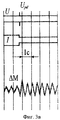
На фиг.1 показана принципиальная схема реализации двухзонного амплитудно-фазового способа перевозбуждения синхронно-гистерезисных электродвигателей.Figure 1 shows a schematic diagram of the implementation of a two-zone amplitude-phase method of overexcitation of synchronous-hysteretic motors.
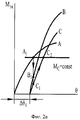
На фиг.2а приведены переходные процессы изменения положения ротора на угловой характеристике.On figa shows transient changes in the position of the rotor on the angular characteristic.
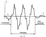
На фиг.2б - намагничивание СГД увеличением импульса тока в течение 3-х периодов питания.On figb - magnetization of SRS by an increase in the current pulse for 3 periods of power.
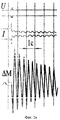
На фиг.2в - колебания тока, момента в результате намагничивания.On figv - fluctuations in current, moment as a result of magnetization.
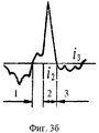
На фиг.3 - аналогичные зависимости оптимизации процесса намагничивания при намагничивании СГД одним импульсом тока.Figure 3 - similar dependence of the optimization of the magnetization process during magnetization of the SRS with a single current pulse.
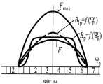
На фиг.4 приведены кривые пространственного распределения магнитодвижущей силы статора МДС (F1, Fmax) и изменения уровня индукции ротора (ВР и B1P) при намагничивании: фиг.4а - характеристики при амплитудном регулировании, фиг.4б - при амплитудно-фазовом регулировании.Figure 4 shows the curves of the spatial distribution of the magnetomotive force of the stator MDS (F 1 , F max ) and changes in the level of induction of the rotor (B P and B 1P ) during magnetization: figa - characteristics with amplitude regulation, fig.4b - with amplitude phase regulation.
Устройство для реализации способа (фиг.1) содержит один или группу синхронно-гистерезисных двигателей 1, подключенных к инвертору напряжения 2, вход которого через блок 3 управляемой вольто-добавки подключен к выпрямителю 4. Схема управления частотой содержит распределитель импульсов 5, который управляет ключами инвертора 2, регулятор фазы 6, один вход которого через делитель частоты 7 подключен к задающему генератору 8, а второй управляющий вход через блок управления регулятором 9 фазы Δα результирующего вектора напряжения соединен с блоком управления 10 режимами перевозбуждения СГД, вход блока управления 10 может быть соединен с программным устройством 11, реализующим либо периодическое подмагничивание, либо подмагничивание в зависимости от степени возбуждения СГД, а другой выход блока управления 10 соединен с блоком 3 управляемой вольто-добавки.A device for implementing the method (Fig. 1) contains one or a group of synchronous-
Работа по способу двухзонного амплитудно-фазового перевозбуждения поясняется на примере работы устройства реализации.The work according to the method of two-zone amplitude-phase overexcitation is illustrated by the example of the operation of the implementation device.
Двигатель или группа двигателей 1 пускаются при включении инвертора 2 по одному из следующих законов:An engine or group of
- частотным способом;- frequency method;
- при постоянной частоте и форсированном напряжении;- at a constant frequency and forced voltage;
- при постоянной частоте и номинальном напряжении питания.- at a constant frequency and rated supply voltage.
Рассмотрим базовый режим, когда пуск двигателя до номинальной частоты fH заканчивается при номинальном напряжении UH, равном пусковому напряжению UП. При этом магнитная система двигателя ненасыщенна, т.е. имеется возможность намагнитить двигатель и достичь режима перевозбуждения путем увеличения напряжения до форсированного уровня UФ.Consider the basic mode, when the engine starts to the rated frequency f H ends at a rated voltage U H equal to the starting voltage U P. In this case, the magnetic system of the engine is unsaturated, i.e. it is possible to magnetize the engine and achieve overexcitation by increasing the voltage to a forced level U f .
Дискретное увеличение или снижение напряжения осуществляется путем включения или отключения вольто-добавки, что сопровождается резким изменением электромагнитного момента СГД и появлением качаний. Это снижает эффективность перевозбуждения и приводит к длительному колебательному процессу движения ротора, соответственно момента, тока и мощности в цепях источника питания.A discrete increase or decrease in voltage is carried out by turning the volt-additive on or off, which is accompanied by a sharp change in the electromagnetic moment of the SRS and the appearance of swings. This reduces the efficiency of overexcitation and leads to a long oscillatory process of rotor movement, respectively, of torque, current and power in the power supply circuits.
Частота колебаний 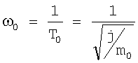
![]()
![]()
Как правило, для высокооборотных электроверетен, центрифуг период собственных колебаний составляет 0,3÷5 с, а ω0=3,3÷0,2 Гц и ниже.As a rule, for high-speed electric spindles, centrifuges, the period of natural vibrations is 0.3–5 s, and ω 0 = 3.3–0.2 Hz and lower.
Появление колебаний при дискретном увеличении напряжения связано со смещением вектора намагниченности ротора относительно тела ротора на угол Δθ и изменением наклона угловой характеристики. На фиг.2а показаны соответственно:The appearance of oscillations with a discrete increase in voltage is associated with a shift of the magnetization vector of the rotor relative to the rotor body by an angle Δθ and a change in the slope of the angular characteristic. On figa shown respectively:
- исходная угловая характеристика А - при UH=UП;- initial angular characteristic A - at U H = U P ;
- характеристика В - при напряжении намагничивания U=UФ;- characteristic B - when the magnetization voltage U = U Ф ;
- характеристика С - при снижении напряжения вновь до напряжения UH=UП.- characteristic C - when the voltage decreases again to a voltage of U H = U P.
Установлено [см. указанный выше аналог, стр.86-90], что процесс намагничивания ротора заканчивается при дискретном регулировании напряжения за десятые доли периода питающего напряжения. Поэтому за время намагничивания инерционный ротор не изменяет своего углового положения в синхронной системе координат, а его движение начинается после намагничивания в соответствии с изменением момента на угловой характеристике. В рассмотренном выше случае - это изменение точки равновесия, когда электромагнитный момент Мэл равен моменту сопротивления Мс, по траектории A1 B1 C1 C2. Точка A1 - исходное положение равновесия, точка С2 - конечная точка равновесия. Смещение угловой характеристики на угол Δθ1 и изменение ее наклона вызывает колебательный процесс движения ротора, что показано на осциллограмме фиг.2в.Installed [see the above analogue, p. 86-90], that the process of magnetization of the rotor ends with discrete regulation of the voltage for tenths of a period of the supply voltage. Therefore, during the magnetization, the inertial rotor does not change its angular position in the synchronous coordinate system, and its movement begins after magnetization in accordance with the change in moment on the angular characteristic. In the case considered above, this is a change in the equilibrium point, when the electromagnetic moment M el is equal to the moment of resistance M s along the path A 1 B 1 C 1 C 2 . Point A 1 is the initial equilibrium position, point C 2 is the final equilibrium point. The shift of the angular characteristic by the angle Δθ 1 and the change in its inclination causes an oscillatory process of the rotor motion, which is shown in the oscillogram of Fig.2c.
Для уменьшения колебательного процесса необходимо процесс увеличения напряжения, создаваемый блоком вольто-добавки 3, сопровождать изменением фазы результирующего вектора напряжения в переходном процессе намагничивания, поворачивая его против направления вращения на угол Δα=15÷20 эл. гр. Выбор этого угла определен расчетом и экспериментально для большинства СГД с учетом того, что максимальный θ по угловой характеристике не превышает 55÷60 эл. гр.To reduce the oscillatory process, it is necessary to increase the voltage created by the volt-
В результате смещение угловой характеристики (фиг.3а) будет меньше, чем аналогичное смещение по фиг.2а (Δθ2<Δθ1), и в идеале может быть обеспечен переходный процесс намагничивания без всяких колебаний или с минимальным возмущением по моменту. На фиг.3б показан процесс импульсного намагничивания, обеспечивший согласование положений угловых характеристик, величин электромагнитного момента и момента сопротивления на фиг.3а, что обеспечивает минимальные колебания ротора (фиг.3в).As a result, the shift in the angular characteristic (Fig. 3a) will be less than the similar displacement in Fig. 2a (Δθ 2 <Δθ 1 ), and ideally, a transient magnetization process can be achieved without any oscillations or with minimal perturbation in time. On figb shows the process of pulsed magnetization, ensuring the coordination of the positions of the angular characteristics, the magnitude of the electromagnetic moment and the moment of resistance in figa, which ensures minimal oscillation of the rotor (figv).
На фиг.3б показан переходный процесс импульсного намагничивания, где цифра 1 отражает ток до намагничивания, цифра 2 - ток в импульсе i2, цифра 3 - ток СГД после намагничивания i3. Дополнительно одновременное изменение импульсов тока по всем фазам СГД приводит к требуемому повороту при намагничивании результирующего вектора напряжения.On figb shows the transient process of pulsed magnetization, where figure 1 reflects the current before magnetization, figure 2 - current in the pulse i 2 , figure 3 - current SRS after magnetization i 3 . Additionally, the simultaneous change in current pulses over all phases of the SRS leads to the required rotation during magnetization of the resulting voltage vector.
Обычно достаточно 3-5 периодов питания для достижения требуемой намагниченности. На фиг.2б показан переходный процесс намагничивания в течение 3-х периодов питания, где соответственно цифрами 1, 2, 3 показаны токи до намагничивания i1, во время намагничивания i2 и после намагничивания i3, когда достигается режим перевозбуждения. Дополнительное регулирование фазы результирующего вектора напряжения на угол Δα в этом случае также минимизирует колебания ротора.Usually 3-5 periods of nutrition are sufficient to achieve the required magnetization. On figb shows the transient magnetization during 3 periods of supply, where, respectively, the
Кроме того, поворот вектора напряжения при намагничивании вносит дополнительный фактор в увеличение уровня намагниченности ротора за счет как увеличения намагниченности всего объема ротора, так и создания вращательного намагничивания, когда вектор магнитодвижущей силы статора изменяется относительно ротора не только по амплитуде, но и по фазе, скользя относительно тела ротора.In addition, the rotation of the voltage vector during magnetization introduces an additional factor in increasing the magnetization level of the rotor due to both an increase in the magnetization of the entire volume of the rotor and the creation of rotational magnetization, when the vector of the stator magnetomotive force changes relative to the rotor not only in amplitude but also in phase, sliding relative to the rotor body.
Для примера на фиг.4а показан процесс амплитудного намагничивания объема ротора, изображенного в виде развернутого полюсного деления (ΨP) с разделением на сектора (ΨP1, ΨР2…ΨP6). Увеличение МДС статора с уровня F1 до Fmax приводит к намагничиванию ротора (кривая ВР=f(Ψ)) с выделением первой гармоники В1Р=f(ΨР). Объемы ротора ΨP1 и ΨP6 получили незначительное подмагничивание, т.к. находились в начале и конце полуволны МДС.For example, FIG. 4a shows the process of amplitude magnetization of the rotor volume, shown in the form of an expanded pole division (Ψ P ) with division into sectors (Ψ P1 , Ψ P2 ... Ψ P6 ). An increase in the stator MDS from level F 1 to F max leads to magnetization of the rotor (curve B P = f (Ψ)) with the first harmonic B 1P = f (Ψ P ) being released. The rotor volumes Ψ P1 and Ψ P6 received a slight bias, because were at the beginning and end of the MDS half-wave.
То же самое увеличение МДС статора с уровня F1 до Fmax и с дополнительным поворотом вектора МДС на угол Δα (фиг.4б) создает дополнительное подмагничивание и в этих объемах (ΨP1 и ΨР6). Результирующая кривая намагничивания ВР=f(ΨР) приобретает уплощенный вид с увеличением первой гармоники ВР1=f(ΨP) по сравнению с аналогичными зависимостями по фиг.4а.The same increase in the stator MDS from the level F 1 to F max and with an additional rotation of the MDS vector by the angle Δα (Fig. 4b) creates additional magnetization in these volumes (Ψ P1 and Ψ P6 ). The resulting magnetization curve B P = f (Ψ P ) takes on a flattened form with an increase in the first harmonic B P1 = f (Ψ P ) in comparison with the similar dependences in figa.
В результате образуется как бы двухзонное намагничивание за счет увеличения МДС статора и дополнительно за счет поворота вектора МДС. Это приводит к увеличению противо ЭДС двигателя, увеличению электромагнитного момента, коэффициента мощности и КПД двигателя. Ориентировочно приращение намагниченности незначительно и составляет 5÷10%, но при желании достичь предельные энергетические показатели это приращение следует учитывать и реализовать через регулирование фазы вектора напряжения с помощью блока 6.As a result, two-zone magnetization forms, as it were, by increasing the stator MDS and, additionally, by rotating the MDS vector. This leads to an increase in the counter emf of the engine, an increase in the electromagnetic moment, power factor and engine efficiency. The approximation of the magnetization increment is insignificant and amounts to 5–10%, but if you want to achieve the limiting energy indices, this increment should be taken into account and implemented through the regulation of the phase of the voltage
Таким образом, амплитудно-фазовое намагничивание при изменении фазы и времени намагничивания в установленных диапазонах позволяет решить две задачи - уменьшение качаний ротора и увеличение общей намагниченности ротора, что увеличивает КПД двигателя до уровня 91-93% при оптимизации всех составляющих: параметров двигателя и алгоритмов управления.Thus, amplitude-phase magnetization when changing the phase and time of magnetization in the established ranges allows us to solve two problems - reducing the swing of the rotor and increasing the total magnetization of the rotor, which increases the efficiency of the motor to a level of 91-93% when optimizing all components: engine parameters and control algorithms .
Увеличение запаса по моменту при намагничивании может быть дополнительно использовано для увеличения отдаваемой мощности СГД, либо при постоянной мощности нагрузки позволяет дополнительно снизить уровень рабочего напряжения, уменьшая этим самым потери в стали и в конструкции изделия.An increase in the torque margin during magnetization can be additionally used to increase the output power of the SRS, or with a constant load power, it can further reduce the level of operating voltage, thereby reducing losses in steel and in the product structure.
Стабилизация энергетических показателей возможна двумя способами:Stabilization of energy indicators is possible in two ways:
- контролем за проявлением дестабилизирующих факторов в системе:- control over the manifestation of destabilizing factors in the system:
сбой по частоте, прерывание питания и т.д. с последующим повторением цикла регулирования возбуждения СГД;frequency failure, power interruption, etc. followed by a repetition of the cycle of regulation of excitation of SRS
- либо периодическим подмагничиванием с частотой импульсов в 3-5 раз выше частоты собственных качаний ротора, что создается программным блоком 11. При этом дополнительно демпфируются колебания ротора.- either by periodic magnetization with a pulse frequency of 3-5 times higher than the frequency of the natural rotor rotations, which is created by the program unit 11. In addition, the rotor vibrations are damped.
Claims (2)
Priority Applications (1)
| Application Number | Priority Date | Filing Date | Title |
|---|---|---|---|
| RU2008112783/09A RU2375813C1 (en) | 2008-04-02 | 2008-04-02 | Method for two-band amplitude-phase overexcitement of synchronous-hysteresis motors |
Applications Claiming Priority (1)
| Application Number | Priority Date | Filing Date | Title |
|---|---|---|---|
| RU2008112783/09A RU2375813C1 (en) | 2008-04-02 | 2008-04-02 | Method for two-band amplitude-phase overexcitement of synchronous-hysteresis motors |
Publications (2)
| Publication Number | Publication Date |
|---|---|
| RU2008112783A RU2008112783A (en) | 2009-10-10 |
| RU2375813C1 true RU2375813C1 (en) | 2009-12-10 |
Family
ID=41260421
Family Applications (1)
| Application Number | Title | Priority Date | Filing Date |
|---|---|---|---|
| RU2008112783/09A RU2375813C1 (en) | 2008-04-02 | 2008-04-02 | Method for two-band amplitude-phase overexcitement of synchronous-hysteresis motors |
Country Status (1)
| Country | Link |
|---|---|
| RU (1) | RU2375813C1 (en) |
Cited By (4)
| Publication number | Priority date | Publication date | Assignee | Title |
|---|---|---|---|---|
| RU2465713C2 (en) * | 2011-02-09 | 2012-10-27 | Открытое Акционерное Общество "Производственное объединение "Электрохимический завод" (ОАО "ПО ЭХЗ") | Method of overexcitation of synchronous hysteresis motor by anchor reaction |
| RU2582201C1 (en) * | 2014-12-24 | 2016-04-20 | Федеральное государственное бюджетное образовательное учреждение высшего профессионального образования Липецкий государственный технический университет (ЛГТУ) | Method of stabilising rotation frequency of synchronous motor |
| RU2637111C1 (en) * | 2016-12-09 | 2017-11-30 | Общество с ограниченной ответственностью "Научно-производственное объединение "Центротех" (ООО "НПО "Центротех") | Device for powering synchronous hysteresis motor with amplitude-phase over-excitation |
| RU2661332C1 (en) * | 2017-03-10 | 2018-07-16 | Общество с ограниченной ответственностью "Научно-производственное объединение "Центротех" (ООО "НПО "Центротех") | Device for supply of a synchronous hysteresis motor with phase overexcitation |
-
2008
- 2008-04-02 RU RU2008112783/09A patent/RU2375813C1/en active
Cited By (4)
| Publication number | Priority date | Publication date | Assignee | Title |
|---|---|---|---|---|
| RU2465713C2 (en) * | 2011-02-09 | 2012-10-27 | Открытое Акционерное Общество "Производственное объединение "Электрохимический завод" (ОАО "ПО ЭХЗ") | Method of overexcitation of synchronous hysteresis motor by anchor reaction |
| RU2582201C1 (en) * | 2014-12-24 | 2016-04-20 | Федеральное государственное бюджетное образовательное учреждение высшего профессионального образования Липецкий государственный технический университет (ЛГТУ) | Method of stabilising rotation frequency of synchronous motor |
| RU2637111C1 (en) * | 2016-12-09 | 2017-11-30 | Общество с ограниченной ответственностью "Научно-производственное объединение "Центротех" (ООО "НПО "Центротех") | Device for powering synchronous hysteresis motor with amplitude-phase over-excitation |
| RU2661332C1 (en) * | 2017-03-10 | 2018-07-16 | Общество с ограниченной ответственностью "Научно-производственное объединение "Центротех" (ООО "НПО "Центротех") | Device for supply of a synchronous hysteresis motor with phase overexcitation |
Also Published As
| Publication number | Publication date |
|---|---|
| RU2008112783A (en) | 2009-10-10 |
Similar Documents
| Publication | Publication Date | Title |
|---|---|---|
| US7116073B1 (en) | Methods and apparatus for controlling a motor/generator | |
| KR101340527B1 (en) | Motor Driver System and Controlling Method for the Same | |
| US7208908B2 (en) | Apparatus and method to control torque and voltage of an AC machine | |
| RU2375813C1 (en) | Method for two-band amplitude-phase overexcitement of synchronous-hysteresis motors | |
| Jiao et al. | Detailed excitation control methods for two-phase brushless exciter of the wound-rotor synchronous starter/generator in the starting mode | |
| EP2802072A1 (en) | Power conversion device | |
| EP3217534B1 (en) | Synchronous electric power distribution startup system | |
| US7135829B1 (en) | Methods and apparatus for controlling a motor/generator | |
| RU2553446C2 (en) | Device for powering of synchronous hysteresis motor | |
| RU2414047C1 (en) | Method and control device to control electric motor with internal permanent magnets | |
| RU2683586C1 (en) | Control method of synchronous electric motor on permanent magnets | |
| JP2538862B2 (en) | Variable speed pumped storage power generation system controller | |
| US10574170B2 (en) | Method for switching off a polyphase electrical machine in a motor vehicle | |
| US6307275B1 (en) | Method and apparatus for controlling a high-speed AC permanent magnet synchronous motor coupled to an industrial turbo engine | |
| EP1753123A2 (en) | Methods and apparatus for controlling a motor/generator | |
| JP3551911B2 (en) | Brushless DC motor control method and device | |
| JP2001238484A (en) | Inverter apparatus | |
| JP2006345583A (en) | Ac power regulator | |
| JP2002010675A (en) | Dc brushless-motor unit | |
| JP5968738B2 (en) | Brushless motor control device | |
| KR101334745B1 (en) | Control of switching angles of a switched reluctance motors | |
| RU2724603C1 (en) | Synchronous motor control method | |
| JP2575629B2 (en) | Variable speed generator motor and control method | |
| Zhang et al. | High frequency injection transient disturbance mitigation for sensorless control of salient pole machines | |
| RU2661332C1 (en) | Device for supply of a synchronous hysteresis motor with phase overexcitation |