RU2375520C1 - Open spillway on non-rock foundation - Google Patents
Open spillway on non-rock foundation Download PDFInfo
- Publication number
- RU2375520C1 RU2375520C1 RU2008129986/03A RU2008129986A RU2375520C1 RU 2375520 C1 RU2375520 C1 RU 2375520C1 RU 2008129986/03 A RU2008129986/03 A RU 2008129986/03A RU 2008129986 A RU2008129986 A RU 2008129986A RU 2375520 C1 RU2375520 C1 RU 2375520C1
- Authority
- RU
- Russia
- Prior art keywords
- tray
- spillway
- water
- gabions
- pipes
- Prior art date
Links
Images

Abstract
Description
Изобретение относится к гидротехническому строительству и может быть использовано при возведении низконапорного или средненапорного открытого водосброса на нескальном основании, как естественного происхождения (береговой водосброс), так и искусственного (водосливная грунтовая плотина).The invention relates to hydraulic engineering and can be used in the construction of low-pressure or medium-pressure open spillway on a rock-free basis, both of natural origin (coastal spillway) and artificial (spillway soil dam).
Известен водосброс [1, стр.414-418], содержащий выполненные из монолитного бетона головную, сбросную (быстроток в виде лотка) и концевую (водобойную) части. Такой водосброс размещается обычно на берегу на скальном или нескальном естественном грунте, который обладает достаточной прочностью, в том числе и фильтрационной, а под днищем лотка предусматривается дренажный элемент.Known spillway [1, p. 414-418], containing the head, discharge (quick flow in the form of a tray) and end (water) parts made of cast concrete. Such a spillway is usually located ashore on rocky or non-rocky natural soil, which has sufficient strength, including filtration, and a drainage element is provided under the bottom of the tray.
Недостатками данного технического решения являются:The disadvantages of this technical solution are:
- высокие затраты, обусловленные большим объемом бетонных работ;- high costs due to the large volume of concrete work;
- жесткость конструкции лотка негативно влияет на его работу, поэтому водослив может разрушиться в результате динамического воздействия потока воды (то же сокращенно поток);- the rigidity of the design of the tray adversely affects its operation, therefore, the spillway may be destroyed as a result of the dynamic impact of the water flow (the same reduced flow);
- водосброс не применим на слабых и просадочных грунтах. Известен водосброс [1, стр.384-388], который отличается от ранее описанного тем, что дно лотка выполнено из тонких клиновидных железобетонных плит на обратном дренаже-фильтре. Такие плиты укладываются в шахматном порядке снизу вверх на низовой откос плотины с напуском верхнего ряда на нижний ряд, что образует гибкое покрытие водосливной части грунтовой плотины, которая закрепленными боковыми откосами или подпорными стенками сопрягается с глухими частями плотины.- spillway is not applicable on weak and subsiding soils. Known spillway [1, p. 384-388], which differs from the previously described in that the bottom of the tray is made of thin wedge-shaped reinforced concrete slabs on the reverse drainage filter. Such slabs are staggered from bottom to top on the lower slope of the dam with the inlet of the upper row on the lower row, which forms a flexible coating of the spillway of the soil dam, which is attached to the blind parts of the dam by fixed side slopes or retaining walls.
Недостатком данного относительно экономичного технического решения является его недостаточная надежность, обусловленная следующими причинами:The disadvantage of this relatively economical technical solution is its lack of reliability due to the following reasons:
- вследствие высокой проницаемости дна лотка происходит насыщение движущейся водой низовой призмы плотины, что повышает требования к материалу дренажа-фильтра и к отводу из него воды, а также обуславливает более пологое выполнение водосливного откоса плотины;- due to the high permeability of the bottom of the tray, the bottom prism of the dam is saturated with moving water, which increases the requirements for the material of the drainage filter and to drain water from it, and also leads to a more gentle execution of the overflow slope of the dam;
динамическое воздействие потока на лоток обуславливает неравномерные деформации обводненного откоса плотины, что может нарушить взаимное зацепление плит и привести к повреждению лотка;the dynamic effect of the flow on the tray causes uneven deformation of the flooded slope of the dam, which can disrupt the mutual engagement of the plates and damage the tray;
- в случае пропуска воды через водосброс в течение всего года низовой откос плотины постоянно насыщен водой, из-за чего снижается ремонтопригодность водосброса, а в суровых климатических условиях может произойти образование на водосбросе наледи, недопустимой по условиям эксплуатации.- in the case of water passage through the spillway throughout the year, the downstream slope of the dam is constantly saturated with water, which reduces the maintainability of the spillway, and in severe climatic conditions, frost can form on the spillway, which is unacceptable under operating conditions.
Известен водосброс [2], который имеет вид быстротока (то же - лотка) трапецеидального поперечного сечения, крепление которого представляет собой цельную гибкую конструкцию, выполненную по всей длине из расположенных на обратном фильтре взаимосвязанных между собой полуцилиндрических габионов. При этом габионы уложены гребнями вверх с ориентацией поперек продольной оси потока, пространство, образованное между полуцилиндрическими габионами, заполнено бетоном, образующим покрытие с деформационными швами по гребням габионов, а входная часть быстротока и его выходная часть посредством габионов заделаны в грунт.Known spillway [2], which has the form of rapid flow (the same - the tray) of a trapezoidal cross-section, the fastening of which is an integral flexible design made along the entire length of the semi-cylindrical gabions interconnected on the inverse filter. At the same time, gabions are stacked with their ridges upward with an orientation transverse to the longitudinal axis of the flow, the space formed between the semi-cylindrical gabions is filled with concrete, forming a coating with expansion joints along the gabion ridges, and the inlet part of the current and its outlet part are embedded into the ground by gabions.
В быстротоке габионы и разрезная бетонная облицовка работают совместно, и они создают цельную гибкую конструкцию. Однако же такое комбинированное крепление быстротока, образованное разрезной бетонной облицовкой, габионами и обратным фильтром, во всех направлениях сильно водопроницаемо, что обуславливает следующие недостатки данного технического решения:In rapid flow, gabions and split concrete cladding work together to create a seamless, flexible structure. However, such a combined fast-current mount formed by split concrete cladding, gabions and a reverse filter is strongly permeable in all directions, which leads to the following disadvantages of this technical solution:
- при уровнях воды перед входной частью быстротока выше подошвы крепления (то же - выше подошвы обратного фильтра) вода движется внутри крепления, причем в турбулентном режиме, и насыщает основание, что повышает требования к материалам обратного фильтра и основания и к отводу из них воды, а также обуславливает более пологий продольный уклон быстротока;- at water levels in front of the inlet part of the quick-flow above the sole of the mount (the same above the sole of the inverse filter), the water moves inside the mount, and in a turbulent mode, and saturates the base, which increases the requirements for the materials of the inverse filter and base and to drain water from them, and also causes a more gentle longitudinal slope of the rapid current;
- бетонное покрытие не обеспечивает достаточную интенсивность гашения энергии потока в пределах сбросной части быстротока, что ограничивает область применения такого быстротока относительно его высоты (перепада уровней воды в бьефах), продольного уклона и удельного расхода воды;- the concrete coating does not provide a sufficient rate of quenching of the flow energy within the discharge part of the flow, which limits the scope of such a flow relative to its height (difference in water levels in the downstream waters), longitudinal slope and specific water flow rate;
- в зимний период года вода из-под крепления будет изливаться на поверхность бетонной облицовки и образовывать наледь, что усложняет эксплуатацию водосброса.- in the winter season, water from the mount will pour onto the surface of the concrete cladding and form ice, which complicates the operation of the spillway.
Наиболее близким техническим решением является водосливная габионная плотина [1, стр.409, 410], тело и водобойная часть которой представляет собой кладку из взаимосвязанных между собой проволокой сетчатых габионов, заполненных камнем и образующих цельную габионную конструкцию, сопрягающуюся с глухими частями плотины. При этом головная часть водосливной габионной плотины содержит бетонную или асфальтобетонную облицовку, а сбросная (водосливная) ее часть выполнена ступенчатой или быстротечной. Противофильтрационным элементом в такой плотине является выполненная из грунта верховая призма или водонепроницаемая облицовка верховой грани плотины.The closest technical solution is a spillway gabion dam [1, p. 409, 410], the body and the water part of which is a masonry of interconnected wire mesh gabions filled with stone and forming a solid gabion structure, mating with the deaf parts of the dam. In this case, the head part of the spillway gabion dam contains concrete or asphalt concrete lining, and the discharge (spillway) part of it is made stepwise or fleeting. An anti-filtration element in such a dam is a top prism made of soil or a waterproof lining of the top face of the dam.
Недостатками данного технического решения являются высокие затраты, ограниченность области применения относительно высоты водосливной плотины и удельных расходов воды, недостаточная надежность и низкая ремонтопригодность, которые обусловлены тем, что:The disadvantages of this technical solution are the high costs, the limited scope of application relative to the height of the spillway dam and the specific consumption of water, insufficient reliability and low maintainability, which are due to the fact that:
- быстро возрастает объем габионной кладки при повышении высоты плотины;- the volume of gabion masonry rapidly increases with increasing dam height;
- слабая интенсивность гашения энергии потока в пределах сбросной части плотины при высоких удельных расходах воды, что обуславливает высокие динамические нагрузки на габионную конструкцию, увеличивающиеся при возрастании высоты плотины;- low rate of quenching of the flow energy within the discharge part of the dam at high specific water flow rates, which leads to high dynamic loads on the gabion structure, increasing with increasing height of the dam;
- недостаточная прочность габионной конструкции;- insufficient strength of the gabion structure;
- восприятие всего сдвигающего гидродинамического воздействия потока осуществляется только габионной конструкцией и ее основанием.- the perception of the entire shear hydrodynamic effects of the flow is carried out only by the gabion structure and its base.
- при пропуске воды происходит водонасыщение низовой призмы плотины, включая частично и ее глухую часть, что обуславливает воздействие направленных в сторону нижнего бьефа объемных фильтрационных сил во всей низовой призме плотины;- when water passes, water saturation of the lower prism of the dam occurs, including partially its deaf part, which causes the effect of volumetric filtration forces directed towards the downstream in the entire lower prism of the dam;
- проведение ремонтных работ без полного прекращения пропуска воды через водосброс затруднено;- carrying out repair work without completely stopping the passage of water through the spillway is difficult;
- происходит обледенение сбросной части в зимний период года.- there is icing of the discharge part in the winter season.
Задачей, на решение которой направлено изобретение, являетсяThe problem to which the invention is directed, is
экономия средств, расширение области применения открытого водосброса соcost savings, expanding the scope of open spillway with
сбросной частью из габионов, повышение надежности и ремонтопригодностиdischarge part of gabions, increasing reliability and maintainability
водосброса.spillway.
Технический результат от использования изобретения заключается в том, что;The technical result from the use of the invention is that;
- уменьшен объем габионной конструкции;- reduced the volume of the gabion structure;
- повышена интенсивность гашения энергии потока в пределах сбросной части;- increased rate of quenching of energy flow within the discharge part;
- повышена надежность габионной конструкции;- increased reliability of the gabion structure;
- уменьшена передача сдвигающего гидродинамического воздействия потока с габионной конструкции в основание сбросной части;- reduced transmission of shear hydrodynamic effects of the flow from the gabion structure to the base of the discharge part;
- предотвращено фильтрационное воздействие в основании сбросной- prevented filtering in the base of the discharge
части;parts;
- предотвращено затопление габионной конструкции плотины при пропуске через водосброс малых меженных расходов воды;- flooding of the gabion structure of the dam was prevented when small low-flow water flows were passed through the spillway;
- при пропуске высоких расходов в лотке снижены удельные расходы открытого потока воды.- when skipping high costs in the tray, the specific costs of the open water flow are reduced.
Указанная задача решается, а технический результат достигается тем, что открытый водосброс на нескальном основании содержит головную часть, выполненную из бетона, сбросную часть, выполненную в виде лотка с быстротечным продольным уклоном и с водобойными стенками на его дне, обеспечивающими образование гидравлических прыжков, концевую часть, выполненную в виде водобоя, по меньшей мере, две трубы, обеспечивающие пропуск малых меженных расходов воды, и естественный или искусственный дренажный элемент в основании лотка. Дно, боковые и водобойные стенки лотка выполнены из заполненных камнями габионов, связанных между собой проволокой и образующих цельную гибкую габионную конструкцию лотка, которая снизу и с боков заключена в водонепроницаемую мембрану. Трубы выполнены из металла, расположены вдоль лотка на габионах его дна по одной у боковой стенки лотка, при этом входной участок трубы пересекает тело водосливного порога головной части и прикреплен к этому порогу. Габионы водобойной стенки расположены с верховой по отношению к направлению потока воды стороны от прикрепленного к трубам жесткого поперечного элемента и прилегают к этому поперечному элементу.This problem is solved, and the technical result is achieved by the fact that the open spillway on a non-rocky base contains a head part made of concrete, a waste part made in the form of a tray with a transient longitudinal slope and with water-borne walls at its bottom, which ensure the formation of hydraulic jumps, the end part made in the form of a water hole, at least two pipes that allow the passage of small low-flow water flows, and a natural or artificial drainage element at the base of the tray. The bottom, side and water walls of the tray are made of gabions filled with stones, connected by a wire and forming an integral flexible gabion structure of the tray, which is enclosed in a waterproof membrane from below and from the sides. The pipes are made of metal, located along the tray on the gabions of its bottom, one at a side of the side wall of the tray, while the inlet section of the pipe crosses the body of the overflow threshold of the head part and is attached to this threshold. The gabions of the watering wall are located on the upper side with respect to the direction of water flow from the rigid transverse element attached to the pipes and are adjacent to this transverse element.
Дополнительно:Additionally:
- продольный уклон дна лотка постоянный или увеличивается в направлении потока;- the longitudinal slope of the bottom of the tray is constant or increases in the direction of flow;
- средняя величина продольного уклона дна лотка icp, доля единицы, удовлетворяет условию:- the average value of the longitudinal slope of the bottom of the tray icp, a fraction of one, satisfies the condition:
0,33>icp>0,20;0.33> i cp >0.20;
- водонепроницаемая мембрана выполнена из полимерной пленки, заключенной в геотекстиль;- the waterproof membrane is made of a polymer film enclosed in geotextiles;
- габионы, прилегающие к трубе, прикреплены к ней;- gabions adjacent to the pipe are attached to it;
- габионы, прилегающие к головной части, прикреплены к ней;- gabions adjacent to the head are attached to it;
- жесткий поперечный элемент представляет собой металлический двутавр, расположенный боком на трубах и упирающийся концами в габионы боковых стенок лотка посредством дополнительных элементов;- the rigid transverse element is a metal I-beam located sideways on the pipes and abutting against the gabions of the side walls of the tray by means of additional elements;
- выходной участок трубы расположен в пределах концевой части водосброса, снабжен плоским опорным элементом и гидравлическим насадком, направляющим выходящую из трубы струю воды от основания.- the outlet pipe section is located within the end part of the spillway, is equipped with a flat supporting element and a hydraulic nozzle directing the water stream leaving the pipe from the base.
Именно:Exactly:
- выполнение лотка в виде цельной гибкой габионной конструкции позволяет уменьшить объем габионной кладки;- the implementation of the tray in the form of an integral flexible gabion structure allows to reduce the volume of gabion masonry;
- выполнение в лотке из габионов водобойных стенок обеспечивает интенсивное гашение энергии потока;- execution in the tray of gabions watering walls provides intensive quenching of energy flow;
- трубы и жесткие поперечные элементы повышают надежность габионной конструкции лотка;- pipes and rigid transverse elements increase the reliability of the gabion design of the tray;
- передача части сдвигающего гидродинамического воздействия потока с габионов посредством жестких поперечных элементов и труб на бетонную головную часть водосброса повышает устойчивость всей габионной конструкции лотка на сдвиг в направлении потока, при этом динамическое воздйствие на головную часть повышает качество сопряжения грунта с бетонными конструкциями головной части;- transfer of a part of the shear hydrodynamic effect of the flow from gabions by means of rigid transverse elements and pipes to the concrete head of the spillway increases the shear stability of the entire gabion design of the tray in the direction of flow, while the dynamic action on the head part improves the quality of soil pairing with the concrete structures of the head part;
- заключение габионной конструкции лотка в водонепроницаемую мембрану полностью предотвращает фильтрационное воздействие воды в основании сбросной части;- the conclusion of the gabion design of the tray in a waterproof membrane completely prevents the filtering effect of water at the base of the discharge part;
- использование труб для пропуска малых меженных расходов воды предотвращает обледенение водосбросной части и упрощает проведение ремонтных работ на водосбросе;- the use of pipes to pass small low-flow water costs prevents icing of the spillway and simplifies the repair work on the spillway;
- при пропуске высоких расходов воды трубы, работающие в напорном режиме при высоких скоростях воды в них, снижают в открытом лотке удельные расходы воды.- when high flow rates of water are passed through, pipes operating in pressure mode at high speeds of water in them reduce the specific flow rates of water in an open tray.
Анализ существующей патентной и научно-технической литературы показал, что предлагаемая совокупность признаков для достижения указанного нового технического результата в настоящее время не известна, что позволяет сделать вывод о наличии как новизны, так и изобретательского уровня.The analysis of the existing patent and scientific and technical literature showed that the proposed set of features to achieve the specified new technical result is not currently known, which allows us to conclude that there is both novelty and inventive step.
Изобретение поясняется чертежами.The invention is illustrated by drawings.
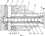
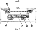
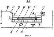
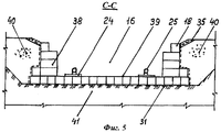
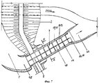
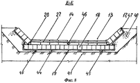
На фиг.1-6 изображен открытый водосброс в виде водосливной (водосбросной) грунтовой плотины, пример 1, а именно: на фиг.1 показан план водосброса; на фиг.2 - продольный разрез водосброса; на фиг 3 -разрез А-А на фиг.2; на фиг.4 - разрез Б-Б на фиг.2; на фиг.5 - разрез С-С на фиг.2; на фиг.6 - разрез Д-Д на фиг.2. На фиг.7 и 8 изображен береговой водосброс, пример 2, а именно: на фиг 7 показан план водосброса; на фиг.8- разрез Е-Е на фиг.7.Figure 1-6 shows an open spillway in the form of a spillway (spillway) soil dam, example 1, namely: figure 1 shows a spillway plan; figure 2 is a longitudinal section of a spillway; in Fig.3 is a section aa in Fig.2; figure 4 is a section bB in figure 2; figure 5 is a section CC in figure 2; Fig.6 is a section DD in Fig.2. Figures 7 and 8 show a coastal spillway, Example 2, namely: Fig. 7 shows a spillway plan; on Fig-section EE in Fig.7.
Пример 1. Водохранилище 1 создано грунтовой плотиной, которая состоит из двух глухих частей 2 и водосливной части 3 (фиг.1). Низовая призма 4 водосливной части 3 плотины и присыпка 5 к ней выполнены из гравийно-галечникового грунта и образуют дренирующее основание 6 открытого водосброса 7, состоящего из головной части 8, сбросной части 9 и концевой части 10.Example 1. The
Головная часть 8 выполнена из бетона и содержит водосливной порог 11, который расположен на гребне ядра 12 водосливной части 3 плотины. Сбросная часть 9 выполнена в виде лотка 13, который имеет быстротечный продольный уклон и водобойные стенки 14 на его дне 15, а концевая часть 10 выполнена в виде расширяющегося в плане водобойного колодца 16.The
Дно 15, боковые стенки 17 и водобойные стенки 14 лотка 13 выполнены из заполненных камнями габионов 18, связанных между собой проволокой и образующих цельную гибкую габионную конструкцию лотка 13, снизу и с боков заключенную в водонепроницаемую мембрану 19, которая выполнена из полимерной пленки и заключена в геотекстиль.The bottom 15, the
Водосброс 7 содержит две трубы 20, которые являются малорасходными, выполнены из металла и расположены вдоль лотка 13 на габионах 18 его дна 15 по одной у каждой боковой стенки 17. Входной участок 21 трубы 20 пересекает тело водосливного порога 11 и прикреплен к этому порогу 11 и покрытию 22. Выходной участок 23 трубы 21 расположен в пределах концевой части 10 водосброса 7, снабжен плоским опорным элементом 24 и гидравлическим насадком 25.The
Габионы 18 водобойной стенки 14 по отношению к направлению потоку воды 26 (далее - поток) в лотке 13 расположены с верховой стороны от жесткого поперечного элемента, который представляет собой двутавр 27, расположен боком на трубах 20 и посредством крепежного элемента 28 прикреплен к ним (фиг.6). Металлический двутавр 27 упирается концами в габионы 18 боковых стенок 17 лотка 13 посредством дополнительных элементов 29, а габионы 18 водобойной стенки 14 прилегают к двутавру 27.
Габионы 18, прилегающие к головной части 8, прикреплены к ней, а габионы 18, прилегающие к трубам 20, прикреплены к этим трубам 20.
Продольный уклон дна 15 лотка 13 в соответствии с работой труб 20 на растяжение постоянный или увеличивается в направлении потока. При этом продольный уклон обеспечивает быстротечное (турбулентное) движение воды в лотке 13, а его средняя величина icp, доля единицы, обычно удовлетворяет условию: 0,33>icp>0,20. Это соответствует заложению дна 15 лотка 13 как 3<m<5. При более крутом уклоне в трубах 20 возникают высокие растягивающие усилия, передающиеся на головную часть 8 водосброса 7, одновременно с этим усложняются работы по выполнению лотка 13. При более пологом уклоне увеличивается длина сбросной части 9 и снижается эффективность работы труб 20 в части восприятия ими сдвигающего воздействия потока на лоток 13.The longitudinal slope of the bottom 15 of the
На чертеже обозначены и другие элементы водосливной части 3 плотины, а именно:The drawing shows other elements of the
30 - верховая призма;30 - mount prism;
31 - геотекстиль;31 - geotextiles;
32 - устой;32 - stand;
33 - открылок;33 - opener;
34 - берма;34 - berm;
35 - откосное крепление;35 - sloping mount;
36 - сифонная ветвь;36 - siphon branch;
37 - поверхность грунтовой воды;37 - surface water table;
38 - стенки водобойного колодца;38 - walls of a water well;
39 - дно водобойного колодца;39 - bottom of a water well;
40 - обратная засыпка;40 - backfill;
41 - основание естественного происхождения.41 - the basis of natural origin.
Водосливную часть 3 плотины возводят одновременно с прилегающими к ней глухими частями 2 плотины до заданного уровня низовой призмы 4, присыпки 5, ядра 12 и верховой призмы 30. Затем на подготовленное основание 6 в пределах концевой части 10 в два слоя укладывают геотекстиль 31, а в пределах сбросной части снизу вверх укладывают мембрану 19. Выполняют габионную кладку водобойного колодца 16 и последовательно снизу вверх габионную кладку лотка 13 с водобойными стенками 14, укладывают трубы 20 и двутавры 27. Бетонируют головную часть 8: водосливной порог 11 с устоями 32 (доковая конструкция), открылки 33 и крепление 22. Через головную часть 8 устраивают мост (на чертежах не показан), завершают отсыпку присыпки 5, выполняют берму 34 и откосное крепление 35. При необходимости к трубе 20 присоединяют сифонную ветвь 36.The
Габионы 18 изготовляют из коробчатых сеток, которые заполняют каменным материалом. Габионы 18 имеют прямоугольную форму с размерами, принятыми, например, в метрах 1×1×2, а диаметр труб 20 принят 0,5 м. При выполнении кладки габионы 18 связывают между собой проволокой с цинковым покрытием. Изготовление габионов 18 и выполнение из них кладки осуществляют в соответствии со стандартами [3-5].
Водосброс 7 работает совместно со всей водосливной плотиной 3 и следующим образом.
При всех уровнях воды в водохранилище 1 дренирующее основание 6 обеспечивает понижение поверхности грунтовой воды 37 ниже водонепроницаемой мембраны 19, что предотвращает взвешивающее воздействие воды на дно 15 лотка 13.At all levels of water in the
Малые меженные расходы пропускаются малорасходными трубами 20, что предотвращает в пределах сбросной части 9 всякое воздействие потока на габионную конструкцию лотка 13 и не создает помехи при осмотре и ремонте лотка. Опорный элемент 24 предотвращают кручение трубы 20, а гидравлический насадок направляет поток воды из трубы 20 от дна 39 водобойного колодца 16. При этом труба 20, выведенная в нижнем бьефе за пределы концевой части 10, при благоприятных условиях позволяет осуществить безнасосную подачу воды потребителю, а снабженная сифонной ветвью 36 эта труба позволяет осуществлять в целях водоснабжения сработку водохранилища 1. При этом за отметку нормально подпорного уровня (▼НПУ) можно принять отметку низа трубы 20 (фиг.2), которая расположена ниже отметки порога 11 (▼nop).Small low-flow costs are passed through low-
При высоких расходах вода в водохранилище 1 может подняться до своего максимального уровня (макс. ▼УВ). При этом большая часть воды движется по лотку 13, водобойные стенки которого совместно с двутаврами 27 обеспечивают перепадную форму течения воды по лотку 13 с образованием прыжка перед каждой водобойной стенкой 14, что обеспечивает интенсивное гашение энергии потока. Одновременно посредством двутавров 27 и труб 20 осуществляется передача части сдвигающего гидродинамического воздействия потока с габионов 18 на все бетонные элементы головной части 8 и на вовлеченный ею грунт плотины, что повышает устойчивость всей габионной конструкции лотка 13 на сдвиг в направлении потока 26. Трубы 20 и двутавры 27 с дополнительными элементами 29 воспринимают боковое давление грунта, передаваемое на них боковыми стенками 17, что повышает устойчивость стенок 17.At high flow rates, the water in
При движении воды по лотку 13 водонепроницаемая мембрана 19 предотвращает водонасыщение низовой призмы 4 плотины, что повышает устойчивость всей габионной конструкции лотка 13 на сдвиг в направлении потока.When water moves along the
Описанный водосброс, как и любой водосброс в виде сливной грунтовой плотины, не занимает на территории новые площади.The described spillway, like any spillway in the form of a drain soil dam, does not occupy new areas on the territory.
Пример 2 (фиг.7 и 8). Береговой водосброс 7 расположен на нескальном основании 41 естественного происхождения и дополнительно содержит подводящий канал 42 и отводящий канал 43.Example 2 (Fig.7 and 8). The
В целях более надежного понижения уровня грунтовой воды 37 в основании 41 ниже водопроницаемой мембраны 19 и увеличения пропускной способности водосброса 7 он может характеризоваться следующими относительно примера 1 отличиями.In order to more reliably lower the level of groundwater 37 in the
1. Мембрана 19 расположена на дренажном слое 44, выполненном на подготовленном нескальном основании 41 естественного происхождения и снабженном дренажными трубами 45.1. The
2. Водосброс 7 содержит дополнительную трубу 46, которая расположена посередине дна лотка 13 и преобразует, таким образом, однопролетный лоток 13 в двухпролетный, а при большем числе дополнительных труб 46 - в многопролетный лоток 13.2. The
3. Боковые стенки 17 лотка 13 выполнены из габионов 18 в виде откосного крепления 47.3. The
Такой береговой водосброс в сравнении с водосбросом, описанным в примере 1, имеет следующие преимущества:Such a coastal spillway in comparison with the spillway described in example 1 has the following advantages:
- работает независимо от плотины;- works regardless of the dam;
- увеличена ширина водосброса, следовательно, и его пропускная способность;- increased width of the spillway, therefore, its throughput;
- повышена надежность и экономичность;- increased reliability and efficiency;
- эффективность работы труб 20 повышена, а их диаметр, как и диаметр дополнительной трубы 47, не требует увязки с размерами габионов.- the efficiency of the
Изобретение позволяет создать открытый водосброс на нескальном основании с лотком из габионной кладки при высоте сооружения до 20-25 м и с удельным расходом воды до 10-12 м3/с на 1 м.The invention allows to create an open spillway on a rocky base with a tray of gabion masonry at a construction height of 20-25 m and with a specific water flow rate of 10-12 m 3 / s per 1 m.
Источники информацииInformation sources
1. Гидротехнические сооружения: Учеб. для вузов: В 2 ч. Ч. 1 / Л.Н.Рассказов, В.Г.Орехов, Ю.П.Правдивцев и др.; Под ред. Л.Н.Рассказова. - М.: Стройиздат, 1999.1. Waterworks: Textbook. for universities: In 2 hours,
2. Патент Российской Федерации №2239021, кл. Е02В 8/06, опубл. 27.10.2004.2. Patent of the Russian Federation No. 2239021, cl.
3. ГОСТ Р 52132-2003 Изделия из сетки для габионных конструкций. Технические условия.3. GOST R 52132-2003 Mesh products for gabion structures. Technical conditions
4. ГОСТ Р 51285-99 Сетки проволочные крученые с шестиугольными ячейками для габионных конструкций. Технические условия.4. GOST R 51285-99 Twisted wire mesh with hexagonal cells for gabion structures. Technical conditions
5. ГОСТ Р 50575-93 Проволока стальная. Требования к цинковому покрытию и методы испытания покрытия.5. GOST R 50575-93 Steel wire. Zinc coating requirements and coating test methods.
Обозначения:Designations:
1 - водохранилище1 - reservoir
2 - глухая часть (плотины)2 - deaf part (dam)
3 - водосливная часть (плотины)3 - spillway (dam)
4 - низовая призма (плотины)4 - bottom prism (dam)
5 - присыпка5 - powder
6 - основание (насыпное)6 - base (bulk)
7 - водосброс7 - spillway
8 - головная часть (водосброса)8 - head part (spillway)
9 - сбросная часть (водосброса)9 - discharge part (spillway)
10 - концевая часть (водосброса)10 - end part (spillway)
11 - водосливной порог (головной части)11 - spillway threshold (head part)
12 - ядро (плотины)12 - core (dam)
13 - лоток (то же - сбросная часть)13 - tray (the same - discharge part)
14 - водобойная стенка14 - water wall
15 - дно (лотка)15 - bottom (tray)
16 - водобойный колодец16 - water well
17 - боковые стенки (лотка)17 - side walls (tray)
18 - габионы18 - gabions
19 - мембрана19 - membrane
20 - труба20 - pipe
21 - входной участок (трубы)21 - inlet section (pipes)
22 - покрытие22 - coating
23 - выходной участок (трубы)23 - output section (pipes)
24 - опорный элемент24 - supporting element
25 - гидравлический насадок25 - hydraulic nozzles
26 - поток воды (далее - поток)26 - water flow (hereinafter referred to as the flow)
27 - двутавр27 - I-beam
28 - крепежный элемент28 - fastener
29 - дополнительный элемент29 - additional element
30 - верховая призма30 - mount prism
31 - геотекстиль31 - geotextiles
32 - устой32 - stand
33 - открылок33 - opener
34 - берма34 - berm
35 - откосное крепление (камнем)35 - sloping mount (stone)
36 - сифонная ветвь36 - siphon branch
37 - поверхность грунтовой воды37 - surface water table
38 - стенки водобойного колодца38 - walls of the water well
39 - дно(водобойного колодца)39 - bottom (water well)
40 - обратная засыпка40 - backfill
41 - основание (естественного происхождения) (Пример 2.)41 - base (natural origin) (Example 2.)
42 - подводящий канал42 - inlet channel
43 - отводящий43 - discharge
44 - дренажный слой44 - drainage layer
45 - дренажная труба45 - drainage pipe
46 - дополнительная труба46 - additional pipe
47 - откосное крепление (габионами).47 - sloping mount (gabions).
Claims (8)
0,33>iср>0,20.3. The spillway according to claim 1, in which the average value of the longitudinal slope of the bottom of the tray i cp , a fraction of one, satisfies the condition:
0.33> i cf. > 0.20.
Priority Applications (1)
| Application Number | Priority Date | Filing Date | Title |
|---|---|---|---|
| RU2008129986/03A RU2375520C1 (en) | 2008-07-21 | 2008-07-21 | Open spillway on non-rock foundation |
Applications Claiming Priority (1)
| Application Number | Priority Date | Filing Date | Title |
|---|---|---|---|
| RU2008129986/03A RU2375520C1 (en) | 2008-07-21 | 2008-07-21 | Open spillway on non-rock foundation |
Publications (1)
| Publication Number | Publication Date |
|---|---|
| RU2375520C1 true RU2375520C1 (en) | 2009-12-10 |
Family
ID=41489614
Family Applications (1)
| Application Number | Title | Priority Date | Filing Date |
|---|---|---|---|
| RU2008129986/03A RU2375520C1 (en) | 2008-07-21 | 2008-07-21 | Open spillway on non-rock foundation |
Country Status (1)
| Country | Link |
|---|---|
| RU (1) | RU2375520C1 (en) |
Cited By (6)
| Publication number | Priority date | Publication date | Assignee | Title |
|---|---|---|---|---|
| CN102644260A (en) * | 2012-05-02 | 2012-08-22 | 黄河勘测规划设计有限公司 | Spillway chute base board covered drainage system |
| RU2498007C1 (en) * | 2012-04-13 | 2013-11-10 | Федеральное государственное бюджетное научное учреждение "Российский научно-исследовательский институт проблем мелиорации" | Reserve spillway of earth dam |
| RU2519845C2 (en) * | 2012-08-20 | 2014-06-20 | Общество с ограниченной ответственностью Научно-производственная фирма "БЕРЕГ" | Water discharge channel of polygonal profile with flexible attachment |
| RU2528835C2 (en) * | 2012-08-31 | 2014-09-20 | Общество с ограниченной ответственностью Научно-производственная фирма "БЕРЕГ" | Method to erect spillway channel of polygonal profile with flexible fixation |
| CN104929086A (en) * | 2015-07-07 | 2015-09-23 | 苏州汇诚智造工业设计有限公司 | Water gate stilling pool base plate reinforcing structure and construction method thereof |
| CN112442987A (en) * | 2020-11-10 | 2021-03-05 | 广东水电二局股份有限公司 | Method for repairing large-area steep slope water outlet building overflow surface by using ultrahigh-performance concrete |
-
2008
- 2008-07-21 RU RU2008129986/03A patent/RU2375520C1/en active
Cited By (6)
| Publication number | Priority date | Publication date | Assignee | Title |
|---|---|---|---|---|
| RU2498007C1 (en) * | 2012-04-13 | 2013-11-10 | Федеральное государственное бюджетное научное учреждение "Российский научно-исследовательский институт проблем мелиорации" | Reserve spillway of earth dam |
| CN102644260A (en) * | 2012-05-02 | 2012-08-22 | 黄河勘测规划设计有限公司 | Spillway chute base board covered drainage system |
| RU2519845C2 (en) * | 2012-08-20 | 2014-06-20 | Общество с ограниченной ответственностью Научно-производственная фирма "БЕРЕГ" | Water discharge channel of polygonal profile with flexible attachment |
| RU2528835C2 (en) * | 2012-08-31 | 2014-09-20 | Общество с ограниченной ответственностью Научно-производственная фирма "БЕРЕГ" | Method to erect spillway channel of polygonal profile with flexible fixation |
| CN104929086A (en) * | 2015-07-07 | 2015-09-23 | 苏州汇诚智造工业设计有限公司 | Water gate stilling pool base plate reinforcing structure and construction method thereof |
| CN112442987A (en) * | 2020-11-10 | 2021-03-05 | 广东水电二局股份有限公司 | Method for repairing large-area steep slope water outlet building overflow surface by using ultrahigh-performance concrete |
Similar Documents
| Publication | Publication Date | Title |
|---|---|---|
| RU2375520C1 (en) | Open spillway on non-rock foundation | |
| US5697736A (en) | Seawalls and shoreline reinforcement systems | |
| US20120117739A1 (en) | Ecologically-Sound Waterway Culvert Restoration | |
| CN207760804U (en) | A kind of Multi-functional economy dike structure | |
| CN103556602B (en) | Structural body for preventing starting of gully debris flows and design method of structural body | |
| CN109610487A (en) | A kind of Larsen steel sheet-pile cofferdam and its construction method | |
| CN110397050B (en) | Beam-anchor type light drainage retaining wall and construction method thereof | |
| CN105239530A (en) | Externally bonded landscape flood prevention wall structure | |
| RU2374387C1 (en) | Water-engineering system on perpetually frozen soils | |
| RU2321701C2 (en) | Weir construction method | |
| CN205062744U (en) | Half gravity type two -stage view anti -flood wall on half cantilever | |
| KR101170789B1 (en) | Complex debris barrier of eco-friendly | |
| CN211395412U (en) | Crossing dyke culvert pipe export protects step structure | |
| CN109355990B (en) | Ultra-fine sand roadbed structure for hydraulic filling in low-lying marsh areas | |
| CN209307794U (en) | Low-level bog area hydraulic reclamation ultra fine sand road structure | |
| CN207277284U (en) | A kind of Combined drawer type bank protection structure | |
| KR20090019127A (en) | System of reverse drain gutter and construction method therewith | |
| RU2266363C1 (en) | Method for flexible interface structure construction | |
| CN111395509B (en) | Construction method of novel assembly type ecological water storage system | |
| CN114032850B (en) | Anti-sliding anchoring structure of spillway at top of rock-fill dam and construction method of anti-sliding anchoring structure | |
| CN112554127B (en) | Bank-keeping member for changing vertical bank line of urban river and construction method thereof | |
| CN210562217U (en) | Water delivery steel pipe structure crossing cutting slope | |
| CN214832735U (en) | Soft foundation reinforcing device for deep sludge layer | |
| CN220619937U (en) | River concrete slope type revetment ecological reconstruction structure | |
| CN214423386U (en) | Protective slope for treating side slope debris flow geological disasters |