RU2364762C2 - Bearing seat with double stiffener - Google Patents
Bearing seat with double stiffener Download PDFInfo
- Publication number
- RU2364762C2 RU2364762C2 RU2005100178/11A RU2005100178A RU2364762C2 RU 2364762 C2 RU2364762 C2 RU 2364762C2 RU 2005100178/11 A RU2005100178/11 A RU 2005100178/11A RU 2005100178 A RU2005100178 A RU 2005100178A RU 2364762 C2 RU2364762 C2 RU 2364762C2
- Authority
- RU
- Russia
- Prior art keywords
- engine
- supporting structure
- bearing
- support
- speed
- Prior art date
Links
- 239000003351 stiffener Substances 0.000 title 1
- 230000000694 effects Effects 0.000 claims abstract 2
- 241000555745 Sciuridae Species 0.000 claims description 2
- 230000005284 excitation Effects 0.000 abstract description 9
- 238000011089 mechanical engineering Methods 0.000 abstract 1
- 239000000126 substance Substances 0.000 abstract 1
- 238000006243 chemical reaction Methods 0.000 description 4
- 238000013016 damping Methods 0.000 description 3
- 238000010586 diagram Methods 0.000 description 3
- 230000002159 abnormal effect Effects 0.000 description 2
- 239000012530 fluid Substances 0.000 description 2
- 230000006978 adaptation Effects 0.000 description 1
- 230000002547 anomalous effect Effects 0.000 description 1
- 230000005540 biological transmission Effects 0.000 description 1
- 230000007547 defect Effects 0.000 description 1
- 230000001419 dependent effect Effects 0.000 description 1
- 238000004519 manufacturing process Methods 0.000 description 1
- 238000005096 rolling process Methods 0.000 description 1
- 238000001228 spectrum Methods 0.000 description 1
Images


Classifications
-
- F—MECHANICAL ENGINEERING; LIGHTING; HEATING; WEAPONS; BLASTING
- F16—ENGINEERING ELEMENTS AND UNITS; GENERAL MEASURES FOR PRODUCING AND MAINTAINING EFFECTIVE FUNCTIONING OF MACHINES OR INSTALLATIONS; THERMAL INSULATION IN GENERAL
- F16F—SPRINGS; SHOCK-ABSORBERS; MEANS FOR DAMPING VIBRATION
- F16F15/00—Suppression of vibrations in systems; Means or arrangements for avoiding or reducing out-of-balance forces, e.g. due to motion
- F16F15/02—Suppression of vibrations of non-rotating, e.g. reciprocating systems; Suppression of vibrations of rotating systems by use of members not moving with the rotating systems
- F16F15/04—Suppression of vibrations of non-rotating, e.g. reciprocating systems; Suppression of vibrations of rotating systems by use of members not moving with the rotating systems using elastic means
- F16F15/06—Suppression of vibrations of non-rotating, e.g. reciprocating systems; Suppression of vibrations of rotating systems by use of members not moving with the rotating systems using elastic means with metal springs
-
- F—MECHANICAL ENGINEERING; LIGHTING; HEATING; WEAPONS; BLASTING
- F01—MACHINES OR ENGINES IN GENERAL; ENGINE PLANTS IN GENERAL; STEAM ENGINES
- F01D—NON-POSITIVE DISPLACEMENT MACHINES OR ENGINES, e.g. STEAM TURBINES
- F01D21/00—Shutting-down of machines or engines, e.g. in emergency; Regulating, controlling, or safety means not otherwise provided for
- F01D21/04—Shutting-down of machines or engines, e.g. in emergency; Regulating, controlling, or safety means not otherwise provided for responsive to undesired position of rotor relative to stator or to breaking-off of a part of the rotor, e.g. indicating such position
- F01D21/045—Shutting-down of machines or engines, e.g. in emergency; Regulating, controlling, or safety means not otherwise provided for responsive to undesired position of rotor relative to stator or to breaking-off of a part of the rotor, e.g. indicating such position special arrangements in stators or in rotors dealing with breaking-off of part of rotor
-
- F—MECHANICAL ENGINEERING; LIGHTING; HEATING; WEAPONS; BLASTING
- F01—MACHINES OR ENGINES IN GENERAL; ENGINE PLANTS IN GENERAL; STEAM ENGINES
- F01D—NON-POSITIVE DISPLACEMENT MACHINES OR ENGINES, e.g. STEAM TURBINES
- F01D25/00—Component parts, details, or accessories, not provided for in, or of interest apart from, other groups
- F01D25/16—Arrangement of bearings; Supporting or mounting bearings in casings
- F01D25/162—Bearing supports
- F01D25/164—Flexible supports; Vibration damping means associated with the bearing
-
- F—MECHANICAL ENGINEERING; LIGHTING; HEATING; WEAPONS; BLASTING
- F16—ENGINEERING ELEMENTS AND UNITS; GENERAL MEASURES FOR PRODUCING AND MAINTAINING EFFECTIVE FUNCTIONING OF MACHINES OR INSTALLATIONS; THERMAL INSULATION IN GENERAL
- F16C—SHAFTS; FLEXIBLE SHAFTS; ELEMENTS OR CRANKSHAFT MECHANISMS; ROTARY BODIES OTHER THAN GEARING ELEMENTS; BEARINGS
- F16C19/00—Bearings with rolling contact, for exclusively rotary movement
- F16C19/02—Bearings with rolling contact, for exclusively rotary movement with bearing balls essentially of the same size in one or more circular rows
- F16C19/04—Bearings with rolling contact, for exclusively rotary movement with bearing balls essentially of the same size in one or more circular rows for radial load mainly
- F16C19/06—Bearings with rolling contact, for exclusively rotary movement with bearing balls essentially of the same size in one or more circular rows for radial load mainly with a single row or balls
-
- F—MECHANICAL ENGINEERING; LIGHTING; HEATING; WEAPONS; BLASTING
- F16—ENGINEERING ELEMENTS AND UNITS; GENERAL MEASURES FOR PRODUCING AND MAINTAINING EFFECTIVE FUNCTIONING OF MACHINES OR INSTALLATIONS; THERMAL INSULATION IN GENERAL
- F16C—SHAFTS; FLEXIBLE SHAFTS; ELEMENTS OR CRANKSHAFT MECHANISMS; ROTARY BODIES OTHER THAN GEARING ELEMENTS; BEARINGS
- F16C27/00—Elastic or yielding bearings or bearing supports, for exclusively rotary movement
- F16C27/04—Ball or roller bearings, e.g. with resilient rolling bodies
-
- F—MECHANICAL ENGINEERING; LIGHTING; HEATING; WEAPONS; BLASTING
- F16—ENGINEERING ELEMENTS AND UNITS; GENERAL MEASURES FOR PRODUCING AND MAINTAINING EFFECTIVE FUNCTIONING OF MACHINES OR INSTALLATIONS; THERMAL INSULATION IN GENERAL
- F16C—SHAFTS; FLEXIBLE SHAFTS; ELEMENTS OR CRANKSHAFT MECHANISMS; ROTARY BODIES OTHER THAN GEARING ELEMENTS; BEARINGS
- F16C2360/00—Engines or pumps
- F16C2360/23—Gas turbine engines
Abstract
Description
Настоящее изобретение относится к опорам подшипников для вращающихся валов двигателей. В частности, оно относится к газотурбинным двигателям.The present invention relates to bearing supports for rotating motor shafts. In particular, it relates to gas turbine engines.
В настоящее время срок службы подшипников качения, газодинамических и масляных подшипников для валов двигателей и конструкции очень сильно зависят от вибрационных характеристик узла двигателя, включающего его раму, передаточный вал, подшипники и опоры.At present, the service life of rolling bearings, gas-dynamic and oil bearings for motor shafts and design are very dependent on the vibration characteristics of the engine assembly, including its frame, transmission shaft, bearings and bearings.
Главные источники вибрационного возбуждения зависят от механической неуравновешенной массы вала двигателя, которая всегда присутствует из-за дефектов производства. Впоследствии основные частоты вибраций, воздействующие на узел двигателя, близки к частоте вращения двигателя.The main sources of vibrational excitation depend on the mechanical unbalanced mass of the motor shaft, which is always present due to manufacturing defects. Subsequently, the main vibration frequencies acting on the engine assembly are close to the engine speed.
По мере увеличения вибрационной реакции каждой упомянутой выше части этого узла увеличивается напряжение подшипников и элементов конструкции, они все больше подвергаются усталости, в результате чего срок их службы сокращается.As the vibrational reaction of each part of this assembly increases, the stress of bearings and structural elements increases, they are more and more subjected to fatigue, as a result of which their service life is reduced.
Эти вибрации наводят также очень сильные шумовые помехи.These vibrations also cause very strong noise interference.
Одно из средств уменьшения амплитуды этих вибраций предусматривает создание опор подшипников, выполненных с возможностью адаптации резонансной частоты по отношению к частоте вращения. Например, опоры подшипников сконструированы так, что их основная резонансная частота сильно отличается от частоты вращения, соответствующей рабочей скорости двигателя.One of the means of reducing the amplitude of these vibrations involves the creation of bearings that are adapted to adapt the resonant frequency with respect to the rotational speed. For example, bearing bearings are designed so that their main resonant frequency is very different from the rotational speed corresponding to the operating speed of the engine.
Но в некоторых случаях двигатель может использоваться при различных скоростях, например при двух скоростях, а именно при низкой скорости и высокой скорости.But in some cases, the engine can be used at different speeds, for example at two speeds, namely at low speed and high speed.
Для преодоления этих проблем предлагались различные решения.Various solutions have been proposed to overcome these problems.
Например, в патенте US 5433584 раскрыта опора для двух подшипников, служащих опорами для вала с обоих концов, опора выполнена с разной жесткостью для каждого из двух подшипников, сочетание двух жесткостей обеспечивает средство ограничения вибраций при нормальной рабочей скорости посредством одного из подшипников и сопротивления аномальной неуравновешенной массе или иному аналогичному аномальному явлению того же типа на другом подшипнике.For example, in US Pat. No. 5,433,584, a bearing is disclosed for two bearings serving as bearings for a shaft at both ends, a bearing is made with different stiffness for each of the two bearings, a combination of two stiffnesses provides a means of limiting vibrations at normal operating speed by one of the bearings and an abnormal unbalanced resistance a mass or other similar anomalous phenomenon of the same type on another bearing.
Это решение не является удовлетворительным, поскольку один из двух подшипников все же находится под воздействием аномального вибрационного уровня в результате упомянутой выше проблемы.This solution is not satisfactory because one of the two bearings is still affected by the abnormal vibration level as a result of the above problem.
В документах US 5110257 и FR 2439331 предложено решение с использованием вязкого демпфирования, текучая среда управляется как функция скорости двигателя для изменения демпфирования опоры во время работы двигателя и таким образом адаптации вибрационного отклика узла во время текущей работы, избавляясь от вышеупомянутого недостатка.In the documents US 5110257 and FR 2439331 a solution using viscous damping is proposed, the fluid is controlled as a function of engine speed to change the damping of the support during engine operation and thus adapt the vibration response of the assembly during current operation, eliminating the aforementioned drawback.
Это решение является сложным, поскольку оно требует использования текучей среды, для которой требуется специальное гидравлическое оборудование, и оно также ограничивается вязким демпфированием.This solution is complex because it requires the use of a fluid, which requires special hydraulic equipment, and it is also limited by viscous damping.
Согласно настоящему изобретению предлагается опора подшипника для вращающегося двигателя, такого как газотурбинный двигатель, с вращающимся валом, опорой для которого служат по меньшей мере один подшипник и рама, способного работать не менее чем с двумя различными рабочими скоростями и содержащего по меньшей мере одну механическую опорную конструкцию с низкой жесткостью и опорную конструкцию с высокой жесткостью, объединенные так, чтобы служить опорой подшипника с одной из этих жесткостей, отличающаяся тем, что опорная конструкция с низкой жесткостью присоединена к опорной конструкции с высокой жесткостью, когда двигатель работает со скоростью, меньшей, чем определенная частота вращения, и отсоединена от опорной конструкции с высокой жесткостью, когда двигатель работает со скоростью выше, чем частота вращения.The present invention provides a bearing support for a rotary engine, such as a gas turbine engine, with a rotating shaft, supported by at least one bearing and a frame capable of operating with at least two different operating speeds and containing at least one mechanical supporting structure with low stiffness and a support structure with high rigidity, combined so as to support the bearing with one of these stiffnesses, characterized in that the support structure with low rigidity attached to the supporting structure with high rigidity when the engine is running at a speed lower than a certain speed, and disconnected from the supporting structure with high rigidity when the engine is running at a speed higher than the speed.
Использование механических конструкций избавляет от присутствия какого-либо гидравлического оборудования, поскольку внесенные таким образом силы жесткости могут непосредственно противодействовать силам возбуждения, генерируемым неуравновешенной массой вала двигателя.The use of mechanical structures eliminates the presence of any hydraulic equipment, since the stiffness forces introduced in this way can directly counteract the excitation forces generated by the unbalanced mass of the motor shaft.
Опорная конструкция с низкой жесткостью служит опорой подшипника, а опорная конструкция с высокой жесткостью служит опорой опорной конструкции с низкой жесткостью, когда двигатель работает с одной из двух скоростей, например с низкой скоростью вращения двигателя, для противодействия неуравновешенной массе вала.The low rigidity support structure serves to support the bearing, and the high rigidity support structure supports the low rigidity support structure when the engine is operated at one of two speeds, for example, at a low engine speed, to counteract the unbalanced shaft mass.
Опора подшипника выполнена с возможностью отделять опорную конструкцию с высокой жесткостью от опорной конструкции с низкой жесткостью, когда двигатель работает с любой из двух скоростей, например высокой скоростью вращения двигателя, конструкция с низкой жесткостью отфильтровывает вибрационное возбуждение, генерируемое неуравновешенной массой вала.The bearing support is configured to separate the support structure with high rigidity from the support structure with low rigidity, when the engine is operated at any of two speeds, for example, a high engine speed, the structure with low rigidity filters out vibrational excitation generated by the unbalanced mass of the shaft.
Предпочтительно опорная конструкция с низкой жесткостью выполнена в форме беличьего колеса для большей упругости.Preferably, the low rigidity support structure is made in the shape of a squirrel wheel for greater elasticity.
В соответствии с другим признаком опора для двигателя, работающего не менее чем с тремя рабочими скоростями, содержит по меньшей мере три опорные механические конструкции с различной жесткостью, объединенные для того, чтобы быть опорой для подшипника с одной из этих жесткостей.In accordance with another feature, a support for an engine operating with at least three operating speeds comprises at least three supporting mechanical structures with different stiffnesses combined to be a support for a bearing with one of these stiffnesses.
Изобретение также относится к сервоуправляющей системе для управления средством приведения в действие одной из конструкций, указанное средство управляется как функция скорости вала или вибрационной амплитуды посредством управляющих компьютеров на двигателе и/или летательном аппарате, на котором установлен двигатель.The invention also relates to a servo control system for controlling a means for driving one of the structures, said means being controlled as a function of shaft speed or vibrational amplitude by means of control computers on the engine and / or the aircraft on which the engine is mounted.
Изобретение будет более понятно после прочтения нижеследующего описания опоры подшипника согласно предпочтительному варианту осуществления изобретения и прилагаемым чертежам, на которых:The invention will be better understood after reading the following description of a bearing support according to a preferred embodiment of the invention and the accompanying drawings, in which:
- на фиг.1 показана частотная диаграмма откликов опорной конструкции под воздействием вибрационного возбуждения ротора двигателя;- figure 1 shows the frequency diagram of the responses of the supporting structure under the influence of vibrational excitation of the rotor of the engine;
- на фиг.2A и 2B показаны продольный и поперечный разрезы подшипника и его опоры согласно изобретению, опорные конструкции соединены; и- figa and 2B shows the longitudinal and transverse sections of the bearing and its bearings according to the invention, the supporting structures are connected; and
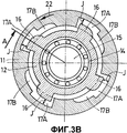
- на фиг.3A и 3B показаны продольный и поперечный разрезы подшипника и его опоры согласно изобретению, опорные конструкции отсоединены.- figa and 3B shows the longitudinal and transverse sections of the bearing and its bearings according to the invention, the supporting structures are disconnected.
Обращаясь к фиг.2A и 2B, на которых фиг.2A представляет собой сечение в направлении А, показанном на фиг.2B, и фиг.2B представляет собой сечение в направлении В, показанном на фиг.2А, вращающийся двигатель содержит раму 10 и вал 15, вращающийся вокруг О оси двигателя, когда он работает.Turning to FIGS. 2A and 2B, in which FIG. 2A is a section in direction A shown in FIG. 2B, and FIG. 2B is a section in direction B shown in FIG. 2A, the rotary engine comprises a
Вал удерживается на месте подшипником 14, в данном случае шарикоподшипником, и опорой 14 подшипника, состоящей из двух коаксиальных опорных конструкций, внешняя конструкция 11 окружает другую, внутреннюю конструкцию 12. Они обе приблизительно конические по форме по направлению к раме 10. Внутренняя конструкция 12 опоры является цилиндрической ближе к подшипнику 14, так что две конструкции объединяются на раме 10 и на подшипнике 14, как описано ниже.The shaft is held in place by a
Внутренняя опорная конструкция 12 присоединена к раме 10 и подшипнику 14. Она присоединена с низкой жесткостью или является упругой.The
Она может быть сконструирована с так называемой формой 13 беличьего колеса для большей упругости.It can be designed with the so-called squirrel-wheel shape 13 for greater elasticity.
Внешняя опорная конструкция 11 значительно жестче, чем внутренняя конструкция, и может быть снабжена ребрами на своей внутренней поверхности. Ребра не показаны.The
Вибрационные характеристики этих опорных конструкций показаны схематично на диаграмме спектра их частотного отклика, приведенной на фиг.1. Они зависят от их соответствующей жесткости, и их использование в описываемом здесь устройстве будет описано ниже.The vibrational characteristics of these supporting structures are shown schematically in the spectrum diagram of their frequency response, shown in figure 1. They depend on their respective stiffness, and their use in the device described here will be described below.
Конечная конструкция 11 на своем конце, близком к раме 10, установлена свободной для перемещения при вращении на раме и на упругой опорной конструкции 12. Она может вращаться вокруг О оси в двух направлениях вращения под воздействием ручного или электрического механического управления посредством подходящего общепринятого средства, не показанного и известного специалистам в данной области, например рычага, электромотора или гидравлического или пневматического подъемного устройства.The
На конце, близком к подшипнику 14, опорная конструкция 11 может вращаться вокруг присоединенной опорной конструкции 12 по дуге, ограниченной радиальными зубцами 16, в данном случае имеются четыре зубца, прикрепленные к этой конечной конструкции 12. Зубцы 16 взаимодействуют с четырьмя пазами 17, образованными на внутренней стороне фланца конструкции 11 перпендикулярно оси вращения. Пазы имеют две части 17A, 17B, днища которых находятся на разном расстоянии от оси.At the end close to the
В положении, показанном на фиг.3A и 3B, зубцы 16 размещены в частях 17A с радиальным зазором J между их вершиной и днищем пазов. Этот зазор больше, чем воздействие неуравновешенной массы вращающегося вала.In the position shown in figa and 3B, the
Части 17В пазов имеют меньший диаметр. Зубцы 16 могут все быть вставлены в пазы одновременно без радиальных зазоров, в точности совпадая по форме.The
Когда зубцы 16 размещены в частях 17B, как показано на фиг.2A и 2B, опорные конструкции 11 и 12 соединены вблизи подшипника. С другой стороны, эти конструкции отсоединены в этом месте на фиг.3A и 3B.When the
Обращаясь к диаграмме на фиг.1, из-за различной жесткости конструкции 11 и 12 имеют вибрационные характеристики такие, что их реакция на вибрационное возбуждение, генерируемое вращением вала на частоте f, может быть представлено кривыми S1, S2 для жесткой конструкции.Turning to the diagram in FIG. 1, due to the different stiffnesses of the
Резонансы MS и MR, показанные этими двумя кривыми, явно разделены, и две кривые пересекаются в точке Mp, соответствующей частоте вращения fp, характеризуемой низкой амплитудой вибрационной реакции для двух конструкций одновременно. На частотах ниже, чем частота fp, жесткая конструкция 11 не имеет значительной реакции R1. На более высоких частотах упругая структура отфильтровывает возбуждения вала 15, и значительной реакции S2 нет, хотя, наоборот, реакции S1 и R2 высоки.The resonances M S and M R shown by these two curves are clearly separated, and the two curves intersect at a point Mp corresponding to a rotational speed fp characterized by a low vibrational response amplitude for the two structures simultaneously. At frequencies lower than the frequency fp, the
Когда внешняя опорная конструкция 11 механически управляется при вращении для вращения в первом направлении 22 на фиг.3B с использованием вышеуказанного управления, она перемещается в положение с более высокой жесткостью, показанное на фиг.2A и 2B. Таким образом, опорная конструкция 12 с низкой жесткостью служит опорой подшипника 14, а опорная конструкция 11 с высокой жесткостью служит опорой опорной конструкции с низкой жесткостью.When the
В этом положении опорные конструкции 11 и 12 полностью соединены и характеристики жесткости узла опоры подшипника определяются характеристиками более жесткой конструкции, которой является внешняя опорная конструкция 11, давая частотную реакцию R1. Это положение регулируется, когда двигатель работает с низкой скоростью, так что опора подшипника противодействует частотным возбуждениям, генерируемым неуравновешенной массой вращающегося вала.In this position, the supporting
Когда внешняя опорная конструкция 11 механически регулируется при вращении для поворота во втором направлении 21 на фиг.2B с использованием вышеупомянутого управления, она перемещается в положение с низкой жесткостью, показанное на фиг.3A и 3B.When the
В этом положении опорные конструкции 11 и 12 отсоединены у подшипника и характеристики жесткости узла опоры подшипника определяются характеристиками более упругой конструкции, которой является внутренняя опорная конструкция 12, давая частотную реакцию R2. Это положение регулируется, когда двигатель работает с высокой скоростью, так что опорная конструкция отфильтровывает вибрационное возбуждение, генерируемое неуравновешенной массой вращающегося вала.In this position, the
Таким образом, для того чтобы оптимизировать адаптацию общих вибрационных характеристик опоры подшипника, внешняя конструкция 11 механически управляется при вращении во втором направлении 21, когда скорость двигателя ниже частоты вращения fp, и в первом направлении 22, когда она выше этой частоты вращения.Thus, in order to optimize the adaptation of the general vibrational characteristics of the bearing support, the
Общий частотный отклик узла двигателя представлен частотной кривой, состоящей из двух ветвей R1 и S2, для которых общий максимум представлен точкой пересечения Mp кривых, представляющих частотные реакции двух конструкций 11 и 12, составляющих опору подшипника двигателя, этот максимум значительно меньше, чем максимум MS и MR двух кривых, представляющих частотные реакции этих двух конструкций.The overall frequency response of the engine assembly is represented by a frequency curve consisting of two branches R1 and S2, for which the total maximum is represented by the intersection point Mp of the curves representing the frequency responses of the two
Claims (7)
Applications Claiming Priority (2)
| Application Number | Priority Date | Filing Date | Title |
|---|---|---|---|
| FR0400220 | 2004-01-12 | ||
| FR0400220A FR2864995B1 (en) | 2004-01-12 | 2004-01-12 | DOUBLE RAIDEUR BEARING SUPPORT |
Publications (2)
| Publication Number | Publication Date |
|---|---|
| RU2005100178A RU2005100178A (en) | 2006-06-20 |
| RU2364762C2 true RU2364762C2 (en) | 2009-08-20 |
Family
ID=34586486
Family Applications (1)
| Application Number | Title | Priority Date | Filing Date |
|---|---|---|---|
| RU2005100178/11A RU2364762C2 (en) | 2004-01-12 | 2005-01-11 | Bearing seat with double stiffener |
Country Status (8)
| Country | Link |
|---|---|
| US (1) | US7524112B2 (en) |
| EP (1) | EP1553324B1 (en) |
| JP (1) | JP4319149B2 (en) |
| CA (1) | CA2492151C (en) |
| DE (1) | DE602005003033T2 (en) |
| ES (1) | ES2293506T3 (en) |
| FR (1) | FR2864995B1 (en) |
| RU (1) | RU2364762C2 (en) |
Cited By (4)
| Publication number | Priority date | Publication date | Assignee | Title |
|---|---|---|---|---|
| RU2541623C1 (en) * | 2014-01-29 | 2015-02-20 | Открытое акционерное общество "Уфимское моторостроительное производственное объединение" ОАО "УМПО" | Resilient support of turbomachine rotor |
| RU2578935C1 (en) * | 2014-10-30 | 2016-03-27 | Открытое акционерное общество "Уфимское моторостроительное производственное объединение" ОАО "УМПО" | Resilient support with adjustable rigidity for bench dynamic test of turbomachine rotors |
| RU2594323C2 (en) * | 2011-09-05 | 2016-08-10 | Снекма | Turbo-machine containing film damping fluid of guide bearing shaft of turbine machine, and method of controlling thickness of said film of damping fluid |
| RU2683334C1 (en) * | 2014-01-20 | 2019-03-28 | Сафран Эркрафт Энджинз | Movable turbomachine element containing means for modification of resonance frequency thereof |
Families Citing this family (35)
| Publication number | Priority date | Publication date | Assignee | Title |
|---|---|---|---|---|
| JP4956995B2 (en) * | 2005-12-27 | 2012-06-20 | トヨタ自動車株式会社 | Bearing support device |
| US7625128B2 (en) | 2006-09-08 | 2009-12-01 | Pratt & Whitney Canada Corp. | Thrust bearing housing for a gas turbine engine |
| US8267650B2 (en) * | 2007-10-30 | 2012-09-18 | Honeywell International Inc. | Sequential stiffness support for bearing assemblies and method of fabrication |
| DE102008004565A1 (en) * | 2008-01-15 | 2009-07-23 | Ab Skf | Active damped bearing arrangement |
| US8702377B2 (en) | 2010-06-23 | 2014-04-22 | Honeywell International Inc. | Gas turbine engine rotor tip clearance and shaft dynamics system and method |
| FR2961865B1 (en) * | 2010-06-28 | 2014-05-09 | Snecma | AIRCRAFT TURBOREACTOR COMPRISING MEANS FOR RECLAIMING THE BLOWER ROTOR DRIVE SHAFT AFTER A DAWN LOSS |
| US8747054B2 (en) | 2011-01-24 | 2014-06-10 | United Technologies Corporation | Bearing system for gas turbine engine |
| US8992161B2 (en) | 2011-08-26 | 2015-03-31 | Honeywell International Inc. | Gas turbine engines including broadband damping systems and methods for producing the same |
| US9046001B2 (en) | 2011-08-29 | 2015-06-02 | Honeywell International Inc. | Annular bearing support dampers, gas turbine engines including the same, and methods for the manufacture thereof |
| FR2982636B1 (en) * | 2011-11-16 | 2014-01-10 | Snecma | BEARING BEARING FOR AIRCRAFT TURBOJET ENGINE COMPRISING IMPROVED MEANS FOR AXIAL RETENTION OF ITS OUTER RING |
| US9297438B2 (en) | 2012-01-25 | 2016-03-29 | Honeywell International Inc. | Three parameter damper anisotropic vibration isolation mounting assembly |
| US9140137B2 (en) | 2012-01-31 | 2015-09-22 | United Technologies Corporation | Gas turbine engine mid turbine frame bearing support |
| US9476320B2 (en) | 2012-01-31 | 2016-10-25 | United Technologies Corporation | Gas turbine engine aft bearing arrangement |
| US9080461B2 (en) | 2012-02-02 | 2015-07-14 | Pratt & Whitney Canada Corp. | Fan and boost joint |
| EP2906798A4 (en) * | 2012-10-09 | 2016-08-03 | United Technologies Corp | Bearing support stiffness control |
| US9790994B2 (en) * | 2014-04-28 | 2017-10-17 | Howden Roots Llc | Device to retain lubricant in a lubricating assembly and implementation thereof |
| US9790825B2 (en) | 2014-04-28 | 2017-10-17 | Howden Roots Llc | Device to direct lubricant in a lubricating assembly and implementation thereof |
| FR3022312B1 (en) * | 2014-06-11 | 2017-03-17 | Snecma | BEARING BEARING ARRANGEMENT WITH TORQUE LIMITING SYSTEM |
| US9714584B2 (en) | 2015-06-18 | 2017-07-25 | United Technologies Corporation | Bearing support damping |
| US9702404B2 (en) | 2015-10-28 | 2017-07-11 | United Technologies Corporation | Integral centering spring and bearing support and method of supporting multiple damped bearings |
| US9869206B2 (en) * | 2016-06-21 | 2018-01-16 | United Technologies Corporation | Securing a centering spring to a static structure with mounting tabs |
| CN107780984B (en) * | 2016-08-31 | 2019-09-20 | 中国航发商用航空发动机有限责任公司 | Can fail rotor support structure and aero-engine |
| US10197102B2 (en) * | 2016-10-21 | 2019-02-05 | General Electric Company | Load reduction assemblies for a gas turbine engine |
| US10274017B2 (en) * | 2016-10-21 | 2019-04-30 | General Electric Company | Method and system for elastic bearing support |
| US10132369B2 (en) * | 2017-01-27 | 2018-11-20 | Hamilton Sundstrand Corporation | Automatically actuated disconnect couplings |
| FR3075897B1 (en) | 2017-12-21 | 2020-01-17 | Safran Aircraft Engines | VARIABLE STRAIGHT BEARING SUSPENSION DEVICE |
| CN108663214B (en) * | 2018-04-28 | 2020-09-18 | 北京航天动力研究所 | Supporting assembly for high-speed rotor analog simulation test and test method |
| DE102018116019A1 (en) * | 2018-07-02 | 2020-01-02 | Rolls-Royce Deutschland Ltd & Co Kg | Bearing device for load reduction |
| DE102018116018A1 (en) | 2018-07-02 | 2020-01-02 | Rolls-Royce Deutschland Ltd & Co Kg | Bearing device for load reduction |
| FR3085408B1 (en) * | 2018-08-28 | 2020-08-07 | Safran Aircraft Engines | TURBOMACHINE IMPROVEMENTS |
| US10844746B2 (en) | 2019-03-29 | 2020-11-24 | Pratt & Whitney Canada Corp. | Bearing housing |
| FR3096744B1 (en) * | 2019-06-03 | 2022-01-14 | Safran Aircraft Engines | AIRCRAFT TURBOMACHINE DRIVE SHAFT SUPPORT AND GUIDE ASSEMBLY |
| US10794222B1 (en) * | 2019-08-14 | 2020-10-06 | General Electric Company | Spring flower ring support assembly for a bearing |
| US11268405B2 (en) | 2020-03-04 | 2022-03-08 | Pratt & Whitney Canada Corp. | Bearing support structure with variable stiffness |
| US11828235B2 (en) | 2020-12-08 | 2023-11-28 | General Electric Company | Gearbox for a gas turbine engine utilizing shape memory alloy dampers |
Family Cites Families (16)
| Publication number | Priority date | Publication date | Assignee | Title |
|---|---|---|---|---|
| DE1575635A1 (en) * | 1967-02-24 | 1970-02-12 | Siemens Ag | Slide or roller bearing arrangement, in particular for electrical machines |
| US4084861A (en) * | 1976-11-11 | 1978-04-18 | United Technologies Corporation | Thrust bearing damping means |
| US4214796A (en) | 1978-10-19 | 1980-07-29 | General Electric Company | Bearing assembly with multiple squeeze film damper apparatus |
| GB2033024A (en) | 1978-10-19 | 1980-05-14 | Gen Electric | Bearing assembly with resilient support means |
| US4872767A (en) * | 1985-04-03 | 1989-10-10 | General Electric Company | Bearing support |
| US5603574A (en) * | 1987-05-29 | 1997-02-18 | Kmc, Inc. | Fluid dampened support having variable stiffness and damping |
| US5531522A (en) * | 1987-05-29 | 1996-07-02 | Kmc, Inc. | Fluid dampened support having variable stiffness and damping |
| US5102236A (en) * | 1987-05-29 | 1992-04-07 | Ide Russell D | Hydrodynamic bearings having a continuous beam mounted support surface |
| US5110257A (en) | 1988-05-12 | 1992-05-05 | United Technologies Corporation | Apparatus for supporting a rotating shaft in a rotary machine |
| US5088840A (en) * | 1990-07-26 | 1992-02-18 | United Technologies Corporation | Dashpot damper |
| US5044784A (en) * | 1990-07-31 | 1991-09-03 | Eaton Corporation | Bearing isolator |
| US5433584A (en) | 1994-05-05 | 1995-07-18 | Pratt & Whitney Canada, Inc. | Bearing support housing |
| FR2749883B1 (en) * | 1996-06-13 | 1998-07-31 | Snecma | METHOD AND BEARING SUPPORT FOR MAINTAINING A TURBOMOTOR FOR AN AIRCRAFT IN OPERATION AFTER AN ACCIDENTAL BALANCE ON A ROTOR |
| SE509392C2 (en) * | 1997-05-27 | 1999-01-18 | Abb Stal Ab | Device for a rotor machine |
| US6325546B1 (en) * | 1999-11-30 | 2001-12-04 | General Electric Company | Fan assembly support system |
| DE10258528B4 (en) * | 2002-12-14 | 2005-10-20 | Mtu Aero Engines Gmbh | Bearing arrangement for a rotating shaft, in particular a gas turbine shaft |
-
2004
- 2004-01-12 FR FR0400220A patent/FR2864995B1/en not_active Expired - Fee Related
- 2004-12-29 US US11/023,501 patent/US7524112B2/en active Active
-
2005
- 2005-01-05 JP JP2005000456A patent/JP4319149B2/en active Active
- 2005-01-06 CA CA2492151A patent/CA2492151C/en active Active
- 2005-01-11 RU RU2005100178/11A patent/RU2364762C2/en active
- 2005-01-11 ES ES05300018T patent/ES2293506T3/en active Active
- 2005-01-11 DE DE602005003033T patent/DE602005003033T2/en active Active
- 2005-01-11 EP EP05300018A patent/EP1553324B1/en active Active
Cited By (4)
| Publication number | Priority date | Publication date | Assignee | Title |
|---|---|---|---|---|
| RU2594323C2 (en) * | 2011-09-05 | 2016-08-10 | Снекма | Turbo-machine containing film damping fluid of guide bearing shaft of turbine machine, and method of controlling thickness of said film of damping fluid |
| RU2683334C1 (en) * | 2014-01-20 | 2019-03-28 | Сафран Эркрафт Энджинз | Movable turbomachine element containing means for modification of resonance frequency thereof |
| RU2541623C1 (en) * | 2014-01-29 | 2015-02-20 | Открытое акционерное общество "Уфимское моторостроительное производственное объединение" ОАО "УМПО" | Resilient support of turbomachine rotor |
| RU2578935C1 (en) * | 2014-10-30 | 2016-03-27 | Открытое акционерное общество "Уфимское моторостроительное производственное объединение" ОАО "УМПО" | Resilient support with adjustable rigidity for bench dynamic test of turbomachine rotors |
Also Published As
| Publication number | Publication date |
|---|---|
| US7524112B2 (en) | 2009-04-28 |
| FR2864995A1 (en) | 2005-07-15 |
| EP1553324B1 (en) | 2007-10-31 |
| RU2005100178A (en) | 2006-06-20 |
| CA2492151A1 (en) | 2005-07-12 |
| ES2293506T3 (en) | 2008-03-16 |
| US20050152626A1 (en) | 2005-07-14 |
| EP1553324A1 (en) | 2005-07-13 |
| DE602005003033T2 (en) | 2008-08-07 |
| DE602005003033D1 (en) | 2007-12-13 |
| JP4319149B2 (en) | 2009-08-26 |
| JP2005201446A (en) | 2005-07-28 |
| CA2492151C (en) | 2012-12-11 |
| FR2864995B1 (en) | 2008-01-04 |
Similar Documents
| Publication | Publication Date | Title |
|---|---|---|
| RU2364762C2 (en) | Bearing seat with double stiffener | |
| US8051710B2 (en) | Method and apparatus for balancing a rotor | |
| US7517155B2 (en) | Resilient mount of uniform stiffness | |
| RU2303143C1 (en) | Rotary machine resilient-damping support | |
| US20060204153A1 (en) | Compact resilient anisotropic support for bearing | |
| EP2989336B1 (en) | Rotating machinery with adaptive bearing journals and methods of operating | |
| JP4954300B2 (en) | Gas turbine rotor | |
| JPH08334117A (en) | Composite shaft | |
| JP2012518750A (en) | Rotor assembly | |
| JPS62294796A (en) | Vacuum pump with casing and rotor | |
| US9341215B2 (en) | Bearing cage with a peripheral vibration damping ring | |
| JPH0345727A (en) | Spindle with single drive device of electric motor type | |
| US4022515A (en) | Support means for textile spindles and rotors having anti-friction bearings | |
| KR100600022B1 (en) | Spindle Apparatus for a main Shaft in a Working Machine with enhanced Dynamic Stiffness | |
| JP4211046B2 (en) | Spindle device | |
| GB2294221A (en) | High-speed machines for grinding eg.blades of rotors for jet engines incorporating supports having elastic articulations selectively actuated during balancing | |
| RU2634512C1 (en) | Resilent damping support with adjustable rigidity | |
| CN117232851A (en) | High-speed rotor failure test device | |
| SU1200005A1 (en) | Elastic support | |
| JPH11187617A (en) | Concentric biaxial simultaneous rotation device means | |
| KR0123250Y1 (en) | Head drum assembly | |
| EP2386779B1 (en) | Rotors for electrical machines | |
| WO2022097030A1 (en) | Compressor device and device equipped with a bearing damper | |
| KR20220062394A (en) | Compressor device with bearing damper and device with bearing damper | |
| JPH03181638A (en) | Propeller shaft for vehicle |
Legal Events
| Date | Code | Title | Description |
|---|---|---|---|
| PD4A | Correction of name of patent owner |