RU2363500C2 - Safe syringe with removable pull-in needle - Google Patents
Safe syringe with removable pull-in needle Download PDFInfo
- Publication number
- RU2363500C2 RU2363500C2 RU2007119986/14A RU2007119986A RU2363500C2 RU 2363500 C2 RU2363500 C2 RU 2363500C2 RU 2007119986/14 A RU2007119986/14 A RU 2007119986/14A RU 2007119986 A RU2007119986 A RU 2007119986A RU 2363500 C2 RU2363500 C2 RU 2363500C2
- Authority
- RU
- Russia
- Prior art keywords
- needle
- rod
- cylinder
- syringe
- sleeve
- Prior art date
Links
Images


Classifications
-
- A—HUMAN NECESSITIES
- A61—MEDICAL OR VETERINARY SCIENCE; HYGIENE
- A61M—DEVICES FOR INTRODUCING MEDIA INTO, OR ONTO, THE BODY; DEVICES FOR TRANSDUCING BODY MEDIA OR FOR TAKING MEDIA FROM THE BODY; DEVICES FOR PRODUCING OR ENDING SLEEP OR STUPOR
- A61M5/00—Devices for bringing media into the body in a subcutaneous, intra-vascular or intramuscular way; Accessories therefor, e.g. filling or cleaning devices, arm-rests
- A61M5/178—Syringes
- A61M5/31—Details
- A61M5/32—Needles; Details of needles pertaining to their connection with syringe or hub; Accessories for bringing the needle into, or holding the needle on, the body; Devices for protection of needles
- A61M5/3205—Apparatus for removing or disposing of used needles or syringes, e.g. containers; Means for protection against accidental injuries from used needles
- A61M5/321—Means for protection against accidental injuries by used needles
- A61M5/322—Retractable needles, i.e. disconnected from and withdrawn into the syringe barrel by the piston
-
- A—HUMAN NECESSITIES
- A61—MEDICAL OR VETERINARY SCIENCE; HYGIENE
- A61M—DEVICES FOR INTRODUCING MEDIA INTO, OR ONTO, THE BODY; DEVICES FOR TRANSDUCING BODY MEDIA OR FOR TAKING MEDIA FROM THE BODY; DEVICES FOR PRODUCING OR ENDING SLEEP OR STUPOR
- A61M5/00—Devices for bringing media into the body in a subcutaneous, intra-vascular or intramuscular way; Accessories therefor, e.g. filling or cleaning devices, arm-rests
- A61M5/50—Devices for bringing media into the body in a subcutaneous, intra-vascular or intramuscular way; Accessories therefor, e.g. filling or cleaning devices, arm-rests having means for preventing re-use, or for indicating if defective, used, tampered with or unsterile
-
- A—HUMAN NECESSITIES
- A61—MEDICAL OR VETERINARY SCIENCE; HYGIENE
- A61M—DEVICES FOR INTRODUCING MEDIA INTO, OR ONTO, THE BODY; DEVICES FOR TRANSDUCING BODY MEDIA OR FOR TAKING MEDIA FROM THE BODY; DEVICES FOR PRODUCING OR ENDING SLEEP OR STUPOR
- A61M5/00—Devices for bringing media into the body in a subcutaneous, intra-vascular or intramuscular way; Accessories therefor, e.g. filling or cleaning devices, arm-rests
- A61M5/178—Syringes
- A61M5/31—Details
- A61M5/32—Needles; Details of needles pertaining to their connection with syringe or hub; Accessories for bringing the needle into, or holding the needle on, the body; Devices for protection of needles
- A61M5/3205—Apparatus for removing or disposing of used needles or syringes, e.g. containers; Means for protection against accidental injuries from used needles
- A61M5/321—Means for protection against accidental injuries by used needles
- A61M5/322—Retractable needles, i.e. disconnected from and withdrawn into the syringe barrel by the piston
- A61M5/3221—Constructional features thereof, e.g. to improve manipulation or functioning
- A61M2005/323—Connection between plunger distal end and needle hub proximal end, e.g. stud protruding from the plunger
-
- A—HUMAN NECESSITIES
- A61—MEDICAL OR VETERINARY SCIENCE; HYGIENE
- A61M—DEVICES FOR INTRODUCING MEDIA INTO, OR ONTO, THE BODY; DEVICES FOR TRANSDUCING BODY MEDIA OR FOR TAKING MEDIA FROM THE BODY; DEVICES FOR PRODUCING OR ENDING SLEEP OR STUPOR
- A61M5/00—Devices for bringing media into the body in a subcutaneous, intra-vascular or intramuscular way; Accessories therefor, e.g. filling or cleaning devices, arm-rests
- A61M5/178—Syringes
- A61M5/31—Details
- A61M5/32—Needles; Details of needles pertaining to their connection with syringe or hub; Accessories for bringing the needle into, or holding the needle on, the body; Devices for protection of needles
- A61M5/3205—Apparatus for removing or disposing of used needles or syringes, e.g. containers; Means for protection against accidental injuries from used needles
- A61M5/321—Means for protection against accidental injuries by used needles
- A61M5/322—Retractable needles, i.e. disconnected from and withdrawn into the syringe barrel by the piston
- A61M5/3221—Constructional features thereof, e.g. to improve manipulation or functioning
- A61M2005/3231—Proximal end of needle captured or embedded inside piston head, e.g. by friction or hooks
-
- A—HUMAN NECESSITIES
- A61—MEDICAL OR VETERINARY SCIENCE; HYGIENE
- A61M—DEVICES FOR INTRODUCING MEDIA INTO, OR ONTO, THE BODY; DEVICES FOR TRANSDUCING BODY MEDIA OR FOR TAKING MEDIA FROM THE BODY; DEVICES FOR PRODUCING OR ENDING SLEEP OR STUPOR
- A61M5/00—Devices for bringing media into the body in a subcutaneous, intra-vascular or intramuscular way; Accessories therefor, e.g. filling or cleaning devices, arm-rests
- A61M5/50—Devices for bringing media into the body in a subcutaneous, intra-vascular or intramuscular way; Accessories therefor, e.g. filling or cleaning devices, arm-rests having means for preventing re-use, or for indicating if defective, used, tampered with or unsterile
- A61M5/5013—Means for blocking the piston or the fluid passageway to prevent illegal refilling of a syringe
- A61M5/502—Means for blocking the piston or the fluid passageway to prevent illegal refilling of a syringe for blocking the piston
Abstract
Description
ОБЛАСТЬ ТЕХНИКИFIELD OF TECHNOLOGY
Данное изобретение относится к безопасному шприцу с втягивающейся иглой, предназначенному для использования в медицинской или зубоврачебной практике или для самостоятельного введения лекарственного средства, так что врач, хирург или кто-либо другой, оперирующий иглой, может быть защищен от ранения иглой после ее использования. В особенности, изобретение относится к безопасным шприцам, когда требуется устанавливать иглы различных размеров или когда необходимо заменить иглу между заполнением шприца из флакона и введением лекарственного средства пациенту путем инъекции.This invention relates to a safe syringe with a retractable needle, intended for use in medical or dental practice or for self-administration of a medicinal product, so that a doctor, surgeon or anyone else operating the needle can be protected from injury by the needle after use. In particular, the invention relates to safe syringes when it is necessary to install needles of various sizes or when it is necessary to replace a needle between filling a syringe from a vial and administering a drug to a patient by injection.
ПРЕДПОСЫЛКИ ИЗОБРЕТЕНИЯBACKGROUND OF THE INVENTION
Опасность ранения или возможность занесения ВИЧ-инфекции или вируса гепатита практикующему медицинскому персоналу, использующему иглы в во время обычной работы, зафиксирована документально.The danger of injury or the possibility of introducing HIV or hepatitis virus to medical practitioners who use needles during normal work is documented.
Кроме того, люди, имеющие обыкновение самостоятельно вводить себе лекарственные средства, подвергаются большой опасности контакта либо с точно определенными вирусами, либо фактически с другими вирусами, если уже использованная игла применяется повторно не в простерилизованном виде. Кроме того, опасность увеличивается, если необходимо выполнять замену иглы в шприце.In addition, people who are used to administering drugs on their own are at great risk of contact with either precisely defined viruses, or in fact with other viruses, if the needle already in use is reused in a non-sterilized form. In addition, the danger increases if it is necessary to replace the needle in the syringe.
В связи с этим было внесено множество предложений, направленных на снижение количества так называемых ранений от укола иглы, а также были предприняты различные попытки, чтобы создать безопасную конструкцию для удаления подобных одноразовых игл, однако такие предложения предшествующего уровня техники имели недостатки.In this regard, many proposals have been made aimed at reducing the number of so-called needle stick injuries, and various attempts have been made to create a safe structure for removing such disposable needles, however, such proposals of the prior art had drawbacks.
ЦЕЛЬ ИЗОБРЕТЕНИЯOBJECT OF THE INVENTION
Целью данного изобретения является создание шприца, содержащего втягивающуюся хирургическую иглу, который обеспечивает возможность установки хирургических игл различных размеров или замены иглы между заполнением шприца из ампулы и введением лекарственного средства пациенту путем инъекции. Кроме того, целью данного изобретения является создание шприца, который использует подобную втягивающуюся иглу, находящуюся в стерильном состоянии до применения, а также для постоянного содержания этой однажды использованной хирургической иглы по существу в безопасном состоянии.The aim of this invention is to provide a syringe containing a retractable surgical needle, which allows the installation of surgical needles of various sizes or replacement of the needle between filling the syringe from the ampoule and administering the drug to the patient by injection. In addition, it is an object of the present invention to provide a syringe that uses a similar retractable needle in a sterile condition prior to use, as well as to keep this once used surgical needle in a substantially safe condition.
По крайней мере, данное изобретение предлагает дополнительное средство обеспечения заменяемой иглы и/или размещения иглы использованного шприца для защиты от случайного ранения, происходящего при нежелательном контакте с открытой иглой сразу после использования шприца.At the very least, this invention provides an additional means of providing a replaceable needle and / or placing the needle of a used syringe to protect against accidental injury resulting from unwanted contact with an open needle immediately after use of the syringe.
Несмотря на то что последующее описание, в общем, относится к шприцу обычного размера, это обстоятельство не является ограничительным, а ссылка на шприц означает любое другое сочетание игла/шприц, включая тонкие шприцы, когда данное изобретение также может быть успешно использовано при соответствующем его приспособлении.Although the following description generally refers to a regular sized syringe, this is not restrictive, and reference to a syringe means any other needle / syringe combination, including thin syringes, when the present invention can also be successfully used with its appropriate device .
СУЩНОСТЬ ИЗОБРЕТЕНИЯSUMMARY OF THE INVENTION
Данное изобретение в одном широком аспекте предлагает безопасный шприц с втягивающейся заменяемой иглой, который имеет цилиндр, содержащий шток, расположенный в нем с возможностью скольжения и имеющий поршень, расположенный на конце штока, удаленном от конца цилиндра, из которого шток выходит, при этом цилиндр шприца дополнительно содержит средство крепления узла иглы с возможностью отсоединения на конце цилиндра, противоположном тому концу, из которого выходит шток, а узел иглы содержит иглу, втулку иглы, составляющую одно целое с иглой, уплотнительное кольцо иглы, предназначенное для размещения иглы и втулки, и колпачок иглы, предназначенный для защиты иглы до ее использования, причем шток содержит средства зацепления, расположенные на его конце и предназначенные для взаимодействия с втулкой иглы для вытягивания иглы из уплотнительного кольца в цилиндр шприца после использования шприца, а шток содержит резьбовую разрезную втулку, при этом шприц отличается тем, что резьбовая разрезная втулка на внутренней стороне имеет многозаходную резьбу, и когда шток с прикрепленной иглой полностью втянут, то имеющееся на штоке по меньшей мере одно утолщение входит в контакт с резьбовой разрезной втулкой, блокируя тем самым шток и, соответственно, иглу в цилиндре, так что шток может быть отломан, а игла удерживается в безопасном состоянии внутри цилиндра шприца.The present invention, in one broad aspect, provides a safe syringe with a retractable replaceable needle, which has a cylinder containing a rod, slidingly located therein and having a piston located at the end of the rod remote from the end of the cylinder from which the rod exits, and the syringe barrel additionally contains means for attaching the needle assembly with the possibility of detachment at the end of the cylinder opposite to the end from which the rod comes out, and the needle assembly comprises a needle, a needle sleeve integral with the needle , a needle o-ring designed to accommodate the needle and the sleeve, and a needle cap designed to protect the needle before use, and the rod contains engagement means located at its end and designed to interact with the needle sleeve to pull the needle from the o-ring into the syringe barrel after using the syringe, and the stem contains a threaded split sleeve, wherein the syringe is characterized in that the threaded split sleeve on the inside has multi-thread, and when the rod is attached If the needle is fully retracted, then at least one thickening on the rod comes into contact with the threaded split sleeve, thereby blocking the rod and, accordingly, the needle in the cylinder, so that the rod can be broken off and the needle is kept in a safe condition inside the syringe barrel .
Предпочтительно уплотнительное кольцо установлено на конце цилиндра с помощью резьбы.Preferably, the o-ring is mounted at the end of the cylinder using threads.
До использования колпачок иглы защищает иглу от повреждения и также служит в качестве защитного колпачка, предотвращающего ранения медицинского персонала, использующего шприц, от укола иглой. Наличие колпачка иглы также предполагает удобную замену узла иглы без риска ранения от укола иглой, который может произойти, если игла была незащищена.Prior to use, the needle cap protects the needle from damage and also serves as a protective cap to prevent injuries to medical personnel using the syringe from needle pricking. The presence of a needle cap also implies a convenient replacement of the needle assembly without the risk of injury from a needle prick, which could occur if the needle was unprotected.
Уплотнительное кольцо для иглы предпочтительно удерживается в колпачке иглы посадкой с натягом. В предпочтительном случае на наружной стороне уплотнительного кольца имеются согласующие шлицы, которые совмещаются со шлицами на внутренней стороне колпачка. Втулка иглы вставлена в уплотнительное кольцо и удерживается на месте согласующимся кольцом, то есть посадкой с натягом. Таким способом достигается герметичное прилегание.The seal ring for the needle is preferably held in the needle cap by a tight fit. In the preferred case, on the outer side of the o-ring there are matching slots that align with the slots on the inside of the cap. The needle sleeve is inserted into the o-ring and held in place by a matching ring, i.e. an interference fit. In this way, a tight fit is achieved.
После сборки, то есть после размещения иглы в уплотнительном кольце и установки защитного колпачка, узел иглы завинчивается в конец цилиндра. Герметизация при этом достигается посредством согласующихся конусов между уплотнительным кольцом иглы и внутренней частью цилиндра, снабженной резьбой.After assembly, that is, after placing the needle in the o-ring and installing the protective cap, the needle assembly is screwed into the end of the cylinder. Sealing is achieved by means of matching cones between the sealing ring of the needle and the inside of the cylinder, equipped with a thread.
Цилиндр шприца предпочтительно выполнен из прозрачного пластика и проградуирован для индикации уровня жидкости. После завинчивания в цилиндр уплотнительного кольца с установленной в нем втулкой иглы и достижения герметизации колпачок иглы снимают с этого узла, приводя иглу в готовое для использования состояние. Таким способом, к цилиндру шприца могут быть присоединены узлы с иглами различных размеров.The syringe barrel is preferably made of transparent plastic and is graduated to indicate liquid level. After screwing the sealing ring into the cylinder with the needle sleeve installed in it and achieving sealing, the needle cap is removed from this assembly, bringing the needle into a state ready for use. In this way, knots with needles of various sizes can be attached to the syringe barrel.
Поршень предпочтительно выполнен из синтетического каучука и прикреплен к штоку с обеспечением уплотнения с помощью посадки с натягом между штоком и цилиндром с обеспечением тем самым возможности вытеснения жидкости из шприца через иглу обычным способом.The piston is preferably made of synthetic rubber and is attached to the stem to provide a seal by interference fit between the stem and cylinder, thereby allowing fluid to be expelled from the syringe through the needle in a conventional manner.
Предпочтительно шток содержит встроенный в его конец зажим, предназначенный для взаимодействия с втулкой иглы после вытеснения штоком жидкости из шприца, то есть после завершения инъекции. После соединения вместе двух сопрягающихся частей шток затем вытягивается назад, вызывая выход использованной втулки иглы вместе со стальной иглой из уплотнительного кольца иглы и ее вытягивание в корпус шприца. Игла теперь присоединена к концу штока и может быть втянута в корпус шприца. Предпочтительно шток имеет место разлома, образованное путем уменьшения его диаметра вблизи поршня. При отламывании штока шприц приводится в нерабочее состояние.Preferably, the stem comprises a clip built into its end for engaging with the needle sleeve after the rod displaces the fluid from the syringe, that is, after completion of the injection. After joining together the two mating parts, the stem is then pulled back, causing the used needle sleeve to exit together with the steel needle from the needle o-ring and pulling it into the syringe body. The needle is now attached to the end of the stem and can be pulled into the syringe body. Preferably, the stem has a fracture formed by reducing its diameter near the piston. When the stem breaks off, the syringe is brought into an inoperative state.
Разрезная резьбовая втулка расположена вокруг стержня штока, вставлена в конец цилиндра и удерживается на месте посадкой с натягом и согласующейся канавкой. Предпочтительно разрезная втулка внутри имеет многозаходную резьбу, так что, когда шток с прикрепленной иглой полностью втянут, то имеющееся на штоке по меньшей мере одно утолщение входит в контакт с резьбовой разрезной втулкой. Когда втулка таким образом вошла в зацепление со штоком, шток тем самым блокируется на конце цилиндра. Затем шток может быть отломан. Место разлома на штоке предпочтительно выполнено с обеспечением его полного отламывания вровень с верхней частью цилиндра, что затрудняет удаление иглы из цилиндра.The split threaded sleeve is located around the stem shaft, is inserted into the end of the cylinder and is held in place by a tight fit and matching groove. Preferably, the split sleeve inside has a multi-thread, so that when the stem with the attached needle is fully retracted, at least one bulge present on the stem comes into contact with the threaded split sleeve. When the sleeve thus engages with the rod, the rod is thereby blocked at the end of the cylinder. Then the stock can be broken off. The place of the fault on the rod is preferably made to ensure its complete breaking off flush with the upper part of the cylinder, which makes it difficult to remove the needle from the cylinder.
Как вариант, данный способ блокирования втулки иглы на штоке может быть противоположным, то есть охватывающая половина может быть расположена в конце втулки иглы, а охватываемый блокирующий выступ - на штоке. Кроме того, данный выступ на конце штока (охватываемая соединительная часть) может содержать зажим из нержавеющей стали, имеющий зубец, который блокируется во втулке иглы при их полном вхождении в зацепление после инъекции медицинской жидкости.Alternatively, this method of locking the needle sleeve on the stem may be the opposite, that is, the female half may be located at the end of the needle sleeve, and the male locking protrusion on the stem. In addition, this protrusion at the end of the stem (male connection part) may include a stainless steel clamp having a tooth that locks in the needle sleeve when it fully engages after injection of medical fluid.
В этом варианте выполнения штампованный зажим из нержавеющей стали выполнен из тонкого листа и проходит поверх охватываемого выступа. Зажим из нержавеющей стали выполнен в форме «С-образной» детали, которая обжимает охватываемый выступ приблизительно на 5 мм длины, причем на одной стороне выполнен зубец, обеспечивающий взаимодействие с внутренней стенкой втулки иглы при завершении инъекции. После извлечения иглы из тела пациента шток оттягивают назад, при этом зубец из нержавеющей стали на штоке, находящийся в заблокированном состоянии во втулке иглы, вызывает втягивание втулки иглы и, соответственно, иглы в корпус цилиндра, переводя иглу в состояние хранения, при котором отсутствует опасность нанесения повреждения человеку. В данном состоянии невозможно отделить иглу от штока, и когда шток втянут и заблокирован в резьбовой разрезной втулке, а затем отломан, шприц приводится в заблокированное состояние и не может быть использован снова. Следует понимать, что выступ на штоке выполнен с посадкой с натягом относительно внутренней части втулки иглы, откуда с очевидностью следует, в каком месте при заполнении шприца до проведения инъекции шток «касается дна» цилиндра шприца. Однако после инъекции необходимо приложить более мощное усилие для преодоления первоначального сопротивления, чтобы действительно заблокировать втулку иглы на штоке.In this embodiment, the stamped stainless steel clamp is made of a thin sheet and extends over the male protrusion. The stainless steel clamp is made in the form of a "C-shaped" part, which compresses the male protrusion by approximately 5 mm in length, with a tooth on one side providing interaction with the inner wall of the needle sleeve at the end of the injection. After removing the needle from the patient’s body, the rod is pulled back, while the stainless steel tooth on the rod, which is in a blocked state in the needle sleeve, causes the needle sleeve and, accordingly, the needle to retract into the cylinder body, placing the needle in a storage state in which there is no danger causing damage to humans. In this state, it is not possible to separate the needle from the stem, and when the stem is retracted and locked in the threaded split sleeve and then broken off, the syringe is locked and cannot be used again. It should be understood that the protrusion on the rod is tightened relative to the inside of the needle sleeve, whence it follows with obviousness where in filling the syringe before the injection the rod “touches the bottom” of the syringe barrel. However, after injection it is necessary to apply a more powerful force to overcome the initial resistance in order to really block the needle sleeve on the rod.
Преимущества данного изобретения заключаются в следующем.The advantages of this invention are as follows.
1. При втягивании иглы вручную предпочтительно используется нержавеющий зажим.1. When retracting the needle by hand, a stainless clip is preferably used.
2. Резьбовая блокирующая разрезная втулка блокирует шток в цилиндре перед отламыванием штока.2. A threaded locking split sleeve blocks the rod in the cylinder before breaking the rod.
3. При использовании вышеуказанных принципов шток может быть втянут без разбрызгивания жидкости, которое вызывается шприцами с автоматическим втягиванием.3. Using the above principles, the stem can be retracted without spraying liquid, which is caused by syringes with automatic retraction.
4. Резьба в узле иглы обеспечивает возможность использования игл разных номеров и/или замены иглы, которая может быть выполнена после заполнения шприца из ампулы до проведения инъекции.4. The thread in the needle assembly allows the use of needles of different numbers and / or replacement of the needle, which can be performed after filling the syringe from the ampoule prior to the injection.
КРАТКОЕ ОПИСАНИЕ ЧЕРТЕЖЕЙBRIEF DESCRIPTION OF THE DRAWINGS
Настоящее изобретение может быть лучше понято из последующего описания неограничивающего предпочтительного варианта выполнения, в котором:The present invention can be better understood from the following description of a non-limiting preferred embodiment, in which:
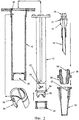
фиг.1 изображает продольный разрез собранного шприца в соответствии с одним аспектом данного изобретения, в котором на конце штока имеется охватывающая соединительная деталь;figure 1 depicts a longitudinal section of an assembled syringe in accordance with one aspect of the present invention, in which at the end of the rod there is a female connecting piece;
фиг.2 изображает покомпонентный разрез деталей, используемых в шприце, показанном на фиг.1;figure 2 depicts an exploded section of the parts used in the syringe shown in figure 1;
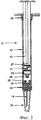
фиг.3 изображает разрез шприца в соответствии со вторым вариантом выполнения данного изобретения, в котором шток имеет охватываемую соединительную деталь;figure 3 depicts a section of a syringe in accordance with a second embodiment of the present invention, in which the rod has a male connection piece;
фиг.4 изображает детальный вид сбоку штока и иглы, предназначенных для использования в шприце в соответствии со вторым вариантом выполнения, показанным на фиг.3;FIG. 4 is a detailed side view of a rod and needle for use in a syringe according to a second embodiment shown in FIG. 3;
фиг.5 изображает зажим из нержавеющей стали, который используется на штоке, показанном на фиг.3 и 4;5 depicts a stainless steel clamp that is used on the stem shown in FIGS. 3 and 4;
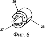
фиг.6 изображает аксонометрический вид разрезной втулки, предназначенной для использования со шприцем по любому из двух вариантов выполнения.6 depicts an axonometric view of a split sleeve designed for use with a syringe according to any one of two embodiments.
ПОДРОБНОЕ ОПИСАНИЕ ЧЕРТЕЖЕЙDETAILED DESCRIPTION OF THE DRAWINGS
Обратимся к фиг.1 и 2, на которых узел из шприца и иглы, в целом обозначенный номером 11 позиции, содержит цилиндр 12 шприца, шток 13 и иглу 14. Игла 14 у ее верхнего конца имеет втулку 15.Turning to FIGS. 1 and 2, in which the assembly of the syringe and needle, generally indicated by
Втулка 15 иглы вставлена в уплотнительное кольцо 16 для иглы и удерживается на месте выступом 17, расположенным по периферии втулки 15, который соединяется с соответствующим пазом 18, расположенным по внутренней периферии уплотнительного кольца 16, посадкой с натягом. Таким способом достигается герметичное прилегание.The
От повреждения иглу защищает колпачок 19 для иглы, который также служит в качестве защитного колпачка, предотвращающего ранения от укола иглой медицинского персонала, использующего шприц.The
Уплотнительное кольцо 16 удерживается в колпачке 19 посадкой с натягом. На наружной стороне уплотнительного кольца 16 имеются согласующие шлицы 20, которые соответствуют взаимодополняющим канавкам 21, расположенным на внутренней стороне колпачка 19. После установки иглы 14 в уплотнительном кольце 16 узел, состоящий из элементов 14, 16, 19, завинчивают в конец 22 цилиндра 12, при этом уплотнение между кольцом 16 и внутренней стороной резьбового участка 22 цилиндра 12 достигается за счет согласующихся конусов.O-
Цилиндр 12 выполнен из прозрачного пластика и проградуирован для индикации уровня жидкости. После завинчивания узла 14, 16, 19 иглы в цилиндр 12 путем завинчивания в него кольца 16 и достижения герметизации колпачок 19 удаляют с этого узла, приводя иглу 14 в готовое для использования состояние. Таким образом, возможна установка в цилиндр 12 узлов 14, 16, 19 с иглами различных размеров.The
Шток 13 содержит поршень 23 из синтетического каучука, который прикреплен к штоку 13 и создает уплотнение за счет посадки с натягом между штоком 13 и цилиндром 12 с обеспечением возможности вытеснения жидкости из шприца 11 обычным способом.The
Шток 13 имеет встроенное в его конец 24 зажимное средство 25, которое в этом варианте выполнения представляет собой охватывающее зажимное приспособление, обеспечивающее зацепление с соответственно предназначенным для этого охватываемым участком 26 на втулке 15 иглы после вытеснения штоком 13 жидкости (не показана) из шприца 11. После соединения сопрягающихся элементов 25, 26 шток 13 оттягивают назад, вызывая выход использованной втулки 15 со стальной иглой 14 из уплотнительного кольца 16. Игла 14 теперь подсоединена к концу штока 13 и может быть втянута в корпус 12 шприца. Шток 13 имеет место 27 разлома, образованное путем уменьшения диаметра вблизи поршня 23. При отламывании штока шприц 11 приводится в нерабочее состояние.The
Вокруг стержня штока 13 расположена разрезная резьбовая втулка 28, вставленная в конец цилиндра 12 и удерживаемая на месте посадкой с натягом, создаваемой выступом 29 на этой втулке и согласующимся пазом 30 в цилиндре 12. Внутри втулки 28 выполнена многозаходная резьба. Когда шток 13 с прикрепленной иглой 14 полностью втянут, то имеющиеся на штоке 13 два утолщения 31 входят в контакт с резьбовой втулкой 28. Когда, таким образом, шток 13 входит в зацепление с втулкой 28, то он блокируется тем самым на конце цилиндра 12. Затем шток 13 может быть отломан у места 27 разлома, которое выполнено с обеспечением его полного отламывания вровень с верхней частью цилиндра 12, затрудняя удаление иглы 14 из цилиндра 12.Around the stem of the
Обратимся к фиг.3, 4 и 5, на которых показан шприц 11, содержащий шток 13 по дополнительному варианту выполнения, при этом детали, аналогичные деталям, показанным на фиг.1 и 2, обозначены теми же номерами позиций. Однако в этом случае способ блокировки втулки 15 иглы на штоке 13 является противоположным и заключается в том, что охватывающий участок 36 расположен на конце втулки 15 иглы, тогда как охватываемый блокирующий выступ 36 расположен на конце штока 13. В этом случае на выступе 36, расположенном на конце штока 13, имеется зажим 33 из нержавеющей стали (показан детально на фиг.5), имеющий зубец 34, который закрепляется с блокированием во втулке иглы 15 при полном вхождении в зацепление после выпуска лечебной жидкости. Штампованный зажим 33 выполнен из тонкого листа нержавеющей стали и проходит поверх охватываемого выступа 32. Зажим из нержавеющей стали выполнен в форме «С-образной» детали, которая обжимает охватываемый выступ 32 приблизительно на 5 мм длины, причем зубец 34 выполнен на одной стороне для обеспечения взаимодействия с внутренней стенкой втулки 15 иглы при окончании инъекции. Зубец 34 может быть выполнен в форме квадрата, как показано на чертеже, или, например, в форме треугольника с острым концом для большего сдерживающего эффекта.Turning to FIGS. 3, 4 and 5, a
После извлечения иглы 14 из тела пациента шток 13 оттягивают, при этом зубец 34 из нержавеющей стали на штоке 13 блокируется во втулке 15 иглы и втягивает втулку 15 и, соответственно, иглу 14 в корпус 12 шприца 11, переводя иглу 14 в скрытое состояние, при котором отсутствует опасность нанесения повреждения человеку. В данном состоянии невозможно отделить иглу 14 от штока 13, и если шток 13 втянут и заблокирован в резьбовой втулке 28 (как показано раньше на фиг.1 и 2), а затем отломан, то шприц 11 тем самым блокируется и не может быть использован снова.After removing the
Фиг.6 показывает другую разрезную втулку 28, предназначенную для использования в любом варианте выполнения, показанном на фиг.1-2 или фиг.3-5, в которой используется четырехзаходная резьба 37.6 shows another
Для специалистов данной области техники должно быть очевидно, что возможно выполнение множества модификаций и изменений вышеприведенных вариантов выполнения без отклонения от сущности или объема правовой охраны данного изобретения.For specialists in this field of technology it should be obvious that it is possible to perform many modifications and changes of the above embodiments without deviating from the essence or scope of legal protection of this invention.
Предполагается, что термин «содержать» и его производные имеют скорее значение «включительно», чем «исключительно», если контекст не требует иного.The term “contain” and its derivatives are intended to be more inclusive than “exclusive” unless the context otherwise requires.
Claims (20)
Applications Claiming Priority (2)
| Application Number | Priority Date | Filing Date | Title |
|---|---|---|---|
| AU2004906332A AU2004906332A0 (en) | 2004-11-04 | Exchange needle retractable safety syringe | |
| AU2004906332 | 2004-11-04 |
Publications (2)
| Publication Number | Publication Date |
|---|---|
| RU2007119986A RU2007119986A (en) | 2008-12-10 |
| RU2363500C2 true RU2363500C2 (en) | 2009-08-10 |
Family
ID=36318810
Family Applications (1)
| Application Number | Title | Priority Date | Filing Date |
|---|---|---|---|
| RU2007119986/14A RU2363500C2 (en) | 2004-11-04 | 2005-04-04 | Safe syringe with removable pull-in needle |
Country Status (14)
| Country | Link |
|---|---|
| US (1) | US20090118677A1 (en) |
| EP (1) | EP1830910A4 (en) |
| JP (1) | JP4791480B2 (en) |
| KR (1) | KR20070097428A (en) |
| CN (1) | CN101094704A (en) |
| AP (1) | AP2007004025A0 (en) |
| BR (1) | BRPI0516705A (en) |
| CA (1) | CA2586705A1 (en) |
| CU (1) | CU23262A3 (en) |
| IL (1) | IL183014A0 (en) |
| MX (1) | MX2007005384A (en) |
| RU (1) | RU2363500C2 (en) |
| WO (1) | WO2006047810A1 (en) |
| ZA (1) | ZA200704624B (en) |
Cited By (3)
| Publication number | Priority date | Publication date | Assignee | Title |
|---|---|---|---|---|
| RU2625288C2 (en) * | 2011-12-08 | 2017-07-12 | Санофи-Авентис Дойчланд Гмбх | Syringe carrier |
| RU2767494C1 (en) * | 2021-05-27 | 2022-03-17 | Игнат Игоревич Иванов | Needle |
| US11400221B2 (en) | 2011-12-08 | 2022-08-02 | Sanofi-Aventis Deutschland Gmbh | Syringe carrier |
Families Citing this family (15)
| Publication number | Priority date | Publication date | Assignee | Title |
|---|---|---|---|---|
| AU2007352135B2 (en) | 2007-04-24 | 2011-09-29 | Morgan Meditech Inc | Single use syringe |
| CN101601882B (en) * | 2009-07-15 | 2012-02-01 | 无锡市宇寿医疗器械股份有限公司 | Disposable safety syringe with replaceable and automatically retracted needle |
| CN101856526B (en) * | 2009-08-15 | 2012-04-11 | 徐昊华 | Disposable safe syringe with automatically-retracted and replaceable needle |
| AU2014200807B2 (en) * | 2009-11-11 | 2015-07-02 | Unitract Syringe Pty Ltd | Vaccination syringe |
| EP2498843A4 (en) * | 2009-11-11 | 2013-10-09 | Unitract Syringe Pty Ltd | Clinical syringe |
| NZ600456A (en) * | 2009-11-11 | 2014-06-27 | Unitract Syringe Pty Ltd | Vaccination syringe |
| CN104151399B (en) * | 2013-05-14 | 2017-11-10 | 中国医学科学院病原生物学研究所 | The shared specificity epitope of bocavirus (HBoV), its application and its antibody |
| GB2529621B (en) * | 2014-08-21 | 2016-12-07 | Owen Mumford Ltd | Safety syringe |
| ITUB20160423A1 (en) * | 2016-02-01 | 2017-08-01 | Umberto Mariani | SAFETY SYSTEM FOR AUTOCLAVABLE SYRINGE |
| FR3053255A1 (en) * | 2016-06-29 | 2018-01-05 | Nicodel S.A. | INJECTION DEVICE |
| KR102043828B1 (en) * | 2017-04-21 | 2019-11-12 | 사회복지법인 삼성생명공익재단 | Medical precision syringe |
| CN115025332A (en) * | 2017-05-05 | 2022-09-09 | 里珍纳龙药品有限公司 | Autoinjector and associated method of use |
| EP4008380A1 (en) * | 2020-12-07 | 2022-06-08 | Trenta2 S.r.l. | Medical syringe |
| CN113425946A (en) * | 2021-06-16 | 2021-09-24 | 江苏苏云医疗器材有限公司 | Anti-acupuncture syringe |
| CN115252966B (en) * | 2022-08-03 | 2023-12-26 | 四川大学华西第二医院 | Composite injector |
Family Cites Families (50)
| Publication number | Priority date | Publication date | Assignee | Title |
|---|---|---|---|---|
| US2004111A (en) * | 1933-04-04 | 1935-06-11 | Heaulme Henri | Apparatus for presenting advertisement-picutres and others |
| US3901413A (en) * | 1974-03-01 | 1975-08-26 | Precision Sampling Corp | High pressure syringe |
| US4386606A (en) * | 1979-12-26 | 1983-06-07 | Waters Instruments, Inc. | Syringe lock |
| US4465472A (en) * | 1982-11-22 | 1984-08-14 | American Hospital Supply Corp. | Syringe cartridge and method |
| US4507117A (en) * | 1983-07-11 | 1985-03-26 | Vining Herbert C | Syringe apparatus with retractable needle |
| US4650468A (en) * | 1986-02-26 | 1987-03-17 | Jennings Jr Baldwin P | Medical syringe |
| US4747830A (en) * | 1986-04-28 | 1988-05-31 | Gloyer Walter W | Anti-stick contagion free disposable hypodermic safety syringe |
| US4675005A (en) * | 1986-05-08 | 1987-06-23 | Deluccia James | Retractable disposable syringe |
| US4790822A (en) * | 1987-12-11 | 1988-12-13 | Haining Michael L | Retractable hypodermic safety syringe |
| ES2008948A6 (en) * | 1988-01-07 | 1989-08-16 | Martinez Gimeno Carlos Vicente | Auto-destructable syringe. |
| US4986813A (en) * | 1988-02-01 | 1991-01-22 | The MadTech Group, Inc. | Disposable hypodermic syringe |
| US4969877A (en) * | 1988-10-19 | 1990-11-13 | The Pascall Medical Corporation | Syringe |
| US5462531A (en) * | 1988-12-14 | 1995-10-31 | Inviro Medical Devices Ltd. | Safety syringe needle device with interchangeable and retractable needle platform |
| US4946446A (en) * | 1989-06-14 | 1990-08-07 | Vadher Dinesh L | Retractable needle |
| GB2233901A (en) * | 1989-07-11 | 1991-01-23 | Hugh Williams | Disposable hypodermic syringe with retractable needle |
| CA2063572A1 (en) * | 1989-07-11 | 1991-01-12 | Graham H. Williams | Disposable hypodermic syringe with retractable needle |
| US5370619A (en) * | 1989-12-20 | 1994-12-06 | Rossi; Lucio | Single-use safety syringe provided with retractile needle and device preventing it from being reused |
| US5066281A (en) * | 1990-03-26 | 1991-11-19 | Stevenson Michener Deborah G C | Disposable syringe apparatus with retractable needle, locking device and cap device |
| US5114404A (en) * | 1990-07-24 | 1992-05-19 | Paxton Gerald R | Multifunctional retractable needle type general purpose disabling syringe having enhanced safety features and related method of operation |
| DK285990A (en) * | 1990-11-30 | 1992-05-31 | Nujenko Pty Ltd | SPRAY UNIT |
| ES2031754A6 (en) * | 1991-02-04 | 1992-12-16 | Melero Redrado Fernando | Self destructive disposable syringe. |
| US5163907A (en) * | 1991-06-24 | 1992-11-17 | Szuszkiewicz Christine M | Single use retractable needle syringe |
| US5188601A (en) * | 1991-11-06 | 1993-02-23 | King Richard J | Disposable safety syringe |
| US5242419A (en) * | 1992-06-15 | 1993-09-07 | Kiner David H | No stick syringe |
| US5222944A (en) * | 1992-10-05 | 1993-06-29 | Harris Edmond L | Safety syringe with retractable and lockable needle |
| US5445620A (en) * | 1993-09-17 | 1995-08-29 | Habley Medical Technology Corp. | Disposable safety syringe with retractable shuttle for Wyeth medication cartridge |
| CA2135706C (en) * | 1993-11-15 | 1999-06-15 | Walter E. Cover | Retractable-needle cannula insertion set with refinements to better control leakage, retraction speed, and reuse |
| US5405327A (en) * | 1994-07-29 | 1995-04-11 | Chen; Long-Hsiung | Simplified safety syringe with retractable self-biased needle and minimized plunger |
| US6090077A (en) * | 1995-05-11 | 2000-07-18 | Shaw; Thomas J. | Syringe plunger assembly and barrel |
| US6090078A (en) * | 1997-09-30 | 2000-07-18 | Becton, Dickinson And Company | Dampening devices and methods for needle retracting safety vascular access devices |
| US6015438A (en) * | 1997-11-14 | 2000-01-18 | Retractable Technologies Inc. | Full displacement retractable syringe |
| TW359621B (en) * | 1998-04-10 | 1999-06-01 | Wen-Neng Liu | Safe injector with injection needle pull-back this invention provides a safe injector with injection needle pull-back which comprises: a needle cylinder, a plunger and an injection needle |
| US5935104A (en) * | 1998-08-21 | 1999-08-10 | Safety Medical Manufacturing, Incorporated | Safety medical syringe with retractable needle |
| US6221052B1 (en) * | 1998-12-18 | 2001-04-24 | Becton, Dickinson And Company | Retracting needle syringe |
| US5971964A (en) * | 1999-01-14 | 1999-10-26 | Donaldson; Neil | Retractable syringe |
| CA2278390C (en) * | 1999-07-19 | 2003-10-07 | Yu-Hau Chang-Lai | Safety syringe |
| US6530903B2 (en) * | 2000-02-24 | 2003-03-11 | Xiping Wang | Safety syringe |
| US6183440B1 (en) * | 2000-05-25 | 2001-02-06 | Becton, Dickinson And Company | Hypodermic syringe having a selectively retractable needle |
| US6206857B1 (en) * | 2000-08-22 | 2001-03-27 | Marina Ling-Ko Chen | Syringe with needle retraction arrangement |
| US20030093038A1 (en) * | 2001-11-15 | 2003-05-15 | Kun-Feng Chiang | Needle retraction type safety syringe |
| US7192418B2 (en) * | 2002-05-10 | 2007-03-20 | Ming-Jeng Shue | Disposable syringe |
| DE10242984B4 (en) * | 2002-09-17 | 2010-09-23 | Sanatis Gmbh | Device for producing mixtures of two components |
| US6846301B2 (en) * | 2002-11-01 | 2005-01-25 | Maxxon, Inc. | Disposable safety syringe |
| US20040210198A1 (en) * | 2003-04-18 | 2004-10-21 | Life-Shield Products, Inc. | Safety retractable type syringe |
| CN1226059C (en) * | 2003-05-21 | 2005-11-09 | 江西洪达医疗器械集团有限公司 | Self-destructible safe syringe |
| US7285110B2 (en) * | 2003-06-10 | 2007-10-23 | P. Rowan Smith, Jr. | Retractable hypodermic safety syringe |
| US6979314B2 (en) * | 2003-10-14 | 2005-12-27 | Syriteck Medical Devices Co., Ltd. | Safety syringe |
| US20050148931A1 (en) * | 2003-10-30 | 2005-07-07 | Juhasz Paul R. | Safety syringe |
| TWM244916U (en) * | 2003-11-07 | 2004-10-01 | Fu-Yi Chen | Safety syringe capable of preventing retraction of needle during suction of medicine or injection |
| TWI256900B (en) * | 2004-04-30 | 2006-06-21 | Ming-Jeng Shiu | Syringe with withdrawal force |
-
2005
- 2005-04-04 AP AP2007004025A patent/AP2007004025A0/en unknown
- 2005-04-04 JP JP2007539419A patent/JP4791480B2/en not_active Expired - Fee Related
- 2005-04-04 EP EP05714360A patent/EP1830910A4/en not_active Withdrawn
- 2005-04-04 CA CA002586705A patent/CA2586705A1/en not_active Abandoned
- 2005-04-04 WO PCT/AU2005/000491 patent/WO2006047810A1/en active Application Filing
- 2005-04-04 RU RU2007119986/14A patent/RU2363500C2/en not_active IP Right Cessation
- 2005-04-04 MX MX2007005384A patent/MX2007005384A/en active IP Right Grant
- 2005-04-04 KR KR1020077012514A patent/KR20070097428A/en not_active Application Discontinuation
- 2005-04-04 US US11/718,638 patent/US20090118677A1/en not_active Abandoned
- 2005-04-04 BR BRPI0516705-1A patent/BRPI0516705A/en not_active IP Right Cessation
- 2005-04-04 CN CNA2005800454465A patent/CN101094704A/en active Pending
-
2007
- 2007-05-04 CU CU20070097A patent/CU23262A3/en not_active IP Right Cessation
- 2007-05-06 IL IL183014A patent/IL183014A0/en unknown
- 2007-06-04 ZA ZA200704624A patent/ZA200704624B/en unknown
Cited By (8)
| Publication number | Priority date | Publication date | Assignee | Title |
|---|---|---|---|---|
| RU2625288C2 (en) * | 2011-12-08 | 2017-07-12 | Санофи-Авентис Дойчланд Гмбх | Syringe carrier |
| US11400221B2 (en) | 2011-12-08 | 2022-08-02 | Sanofi-Aventis Deutschland Gmbh | Syringe carrier |
| US11400222B2 (en) | 2011-12-08 | 2022-08-02 | Sanofi-Aventis Deutschland Gmbh | Syringe carrier |
| US11400223B2 (en) | 2011-12-08 | 2022-08-02 | Sanofi-Aventis Deutschland Gmbh | Syringe carrier |
| US11406764B2 (en) | 2011-12-08 | 2022-08-09 | Sanofi-Aventis Deutschland Gmbh | Syringe carrier |
| US11406763B2 (en) | 2011-12-08 | 2022-08-09 | Sanofi-Aventis Deutschland Gmbh | Syringe carrier |
| US11511043B2 (en) | 2011-12-08 | 2022-11-29 | Sanofi-Aventis Deutschland Gmbh | Syringe carrier |
| RU2767494C1 (en) * | 2021-05-27 | 2022-03-17 | Игнат Игоревич Иванов | Needle |
Also Published As
| Publication number | Publication date |
|---|---|
| RU2007119986A (en) | 2008-12-10 |
| JP2008518693A (en) | 2008-06-05 |
| US20090118677A1 (en) | 2009-05-07 |
| EP1830910A1 (en) | 2007-09-12 |
| EP1830910A4 (en) | 2009-09-09 |
| IL183014A0 (en) | 2007-08-19 |
| JP4791480B2 (en) | 2011-10-12 |
| ZA200704624B (en) | 2008-08-27 |
| CA2586705A1 (en) | 2006-05-11 |
| KR20070097428A (en) | 2007-10-04 |
| AP2007004025A0 (en) | 2007-06-30 |
| CU23262A3 (en) | 2008-02-20 |
| WO2006047810A1 (en) | 2006-05-11 |
| MX2007005384A (en) | 2007-09-27 |
| BRPI0516705A (en) | 2008-09-23 |
| CN101094704A (en) | 2007-12-26 |
Similar Documents
| Publication | Publication Date | Title |
|---|---|---|
| RU2363500C2 (en) | Safe syringe with removable pull-in needle | |
| CA2601431C (en) | Auto retractable syringe | |
| RU2459639C2 (en) | Disposable cartridge injector | |
| US20140039413A1 (en) | Needle assembly for a medical device | |
| US20090171287A1 (en) | Single use safety syringe having a retractable needle | |
| BRPI0315217B1 (en) | "single use syringe assembly having a safety shield" | |
| US20070123830A1 (en) | Safety syringe | |
| JP2008534179A (en) | Retraction control of needle in automatic retractable syringe | |
| WO2006096901A1 (en) | Exchange needle auto retractable syringe | |
| JP2008512150A (en) | Safety syringe | |
| US20120191041A1 (en) | Safety syringe | |
| EA012008B1 (en) | Auto retractable syringe | |
| US20080208119A1 (en) | Safety Syringe With Retractable Needle Utilising Spring Clip On Plunger | |
| RU2663645C1 (en) | Disposable cartridge injector | |
| AU2006225069B8 (en) | Auto retractable syringe | |
| WO1993002726A1 (en) | Improvements in or relating to syringes | |
| AU2006230789A1 (en) | Safety syringe with retractable needle utilising spring clip on plunger | |
| AU2005301081A1 (en) | Exchange needle retractable safety syringe | |
| MX2008003210A (en) | Single use safety syringe having a retractable needle | |
| AU2006289645A1 (en) | Single use safety syringe having a retractable needle | |
| ZA200700199B (en) | Retractable needle for a syringe | |
| NZ270353A (en) | Disposable hypodermic syringe; details regarding means for adapting existing syringes to capture and retain needle cannula in syringe cylinder after expulsion of medicament |
Legal Events
| Date | Code | Title | Description |
|---|---|---|---|
| MM4A | The patent is invalid due to non-payment of fees |
Effective date: 20110405 |