RU2362876C2 - Miner for excavation of minerals and procedure for their excavation - Google Patents
Miner for excavation of minerals and procedure for their excavation Download PDFInfo
- Publication number
- RU2362876C2 RU2362876C2 RU2008110870/03A RU2008110870A RU2362876C2 RU 2362876 C2 RU2362876 C2 RU 2362876C2 RU 2008110870/03 A RU2008110870/03 A RU 2008110870/03A RU 2008110870 A RU2008110870 A RU 2008110870A RU 2362876 C2 RU2362876 C2 RU 2362876C2
- Authority
- RU
- Russia
- Prior art keywords
- combine
- handle
- hydraulic
- housing
- harvester
- Prior art date
Links
Images


Landscapes
- Guiding Agricultural Machines (AREA)
- Harvesting Machines For Root Crops (AREA)
Abstract
Description
Настоящее изобретение относится к горному очистному комбайну для выемки пластовых полезных ископаемых и способу их выемки с его помощью в подземных условиях из пологих и наклонных пластов мощностью от 1,2 до 3,0 м и более и может быть использован для отработки пластов угля, солей и мерзлых золотоносных песков.The present invention relates to a mining shearer for extracting formation minerals and a method for extracting it using underground from shallow and inclined formations with a thickness of 1.2 to 3.0 m or more and can be used for mining coal seams, salts and frozen gold sands.
Более точно изобретение касается комбайна для выемки пластовых полезных ископаемых, в частности пластов угля с породными включениями, содержащего корпус с размещенными в нем электрическим и гидравлическим блоками с их пультами управления и механизм для поступательного перемещения комбайна, взаимодействующий с цевочной рейкой конвейера, а также, по меньшей мере, одну расположенную с торца корпуса поворотную в вертикальной плоскости комбайна рукоять с исполнительным органом для отбойки полезного ископаемого, приводимым во вращение с помощью размещенных внутри рукояти двигателя и редуктора.More precisely, the invention relates to a combine for the extraction of reservoir minerals, in particular coal seams with rock inclusions, comprising a housing with electric and hydraulic units located therein with their control panels and a mechanism for translational movement of the combine interacting with the transmission pin rail, as well as at least one handle located at the end of the housing in the vertical plane of the combine harvester with an actuator for breaking minerals, driven into rotation by with power placed inside the handle of the engine and gearbox.
Изобретение также касается способа выемки пластовых полезных ископаемых с помощью двух одновременно работающих в одной лаве очистных комбайнов, поступательно перемещающихся по цевочной рейке лавного конвейера и несущих по меньшей мере одну поворотную в вертикальной плоскости комбайна рукоять с вращающимся исполнительным органом для отбойки полезного ископаемого.The invention also relates to a method for extracting reservoir minerals using two shearers operating simultaneously in the same lava, translationally moving along the foreline of the lava conveyor and carrying at least one handle rotatable in the vertical plane of the combine with a rotating actuator for breaking the mineral.
В настоящее время для высокопродуктивной выемки пластовых полезных ископаемых используют два одновременно работающих в одной лаве очистных комбайна, при этом рациональная длина лавы может варьироваться от 250 до 350 м.At present, for the highly productive extraction of reservoir minerals, two shearers operating simultaneously in the same lava are used, while the rational length of the lava can vary from 250 to 350 m.
Однако заметным сдерживающим фактором для высокопродуктивной добычи могут быть породные включения крепостью обычно от 6 до 12 единиц по шкале Протодьяконова (f=6-12) в разрабатываемом пласте полезного ископаемого. Указанные породные включения могут проявляться различно.However, rock inclusions with a strength usually from 6 to 12 units on the Protodyakonov scale (f = 6-12) in the developed mineral layer can be a significant deterrent to highly productive mining. These breed inclusions can manifest themselves in various ways.
В одних случаях это могут быть наплывы внутрь разрабатываемого пласта как со стороны кровли, так и со стороны почвы, либо в виде отдельных линз или пропластков в массиве пласта.In some cases, these can be inflows into the developed formation both from the roof and from the soil, or in the form of separate lenses or layers in the array of the formation.
В других случаях, например в результате геологических нарушений (сдвигов, сбросов и так далее), породные включения упомянутой выше крепости могут проходить по всей мощности разрабатываемого пласта и располагаться на достаточно большом расстоянии по простиранию разрабатываемого пласта.In other cases, for example, as a result of geological disturbances (shifts, discharges, and so on), rock inclusions of the aforementioned fortress can pass through the entire power of the developed formation and be located at a sufficiently large distance along the strike of the developed formation.
Известные для выемки пластов полезного ископаемого комбайны, имеющие смонтированные на поворотных в вертикальной плоскости рукоятях исполнительные органы для отбойки полезного ископаемого в виде приводимого во вращение шнека с резцами, могут сравнительно эффективно разрушать встречающиеся в пласте по ходу движения комбайна породные включения с крепостью по Протодьяконову максимум до f=8.Combine harvesters known for excavation of mineral deposits that have actuators mounted on vertical arms that rotate in a vertical plane to break the mineral in the form of a rotary auger with cutters can comparatively effectively destroy rock inclusions with Protodyakonov fortress up to a maximum of up to a maximum f = 8.
Эффективная работа известной конструкции комбайнов прекращается или резко уменьшается при встрече в разрабатываемом пласте полезного ископаемого породных включений крепостью f=8-12. Попытки продолжить разрабатывать пласт с такой крепостью породных включений комбайнами известной конструкции становятся невозможными по ряду причин.The effective work of the well-known design of combines stops or decreases sharply when meeting in the developed layer of mineral fossil rock inclusions with a strength of f = 8-12. Attempts to continue to develop a reservoir with such a rock strength by combines of known design become impossible for a number of reasons.
Повышение сопротивления резанию по породным включениям приводит соответственно к увеличению расхода режущего инструмента, которым оснащен шнек исполнительного органа. Приводящие во вращение исполнительный орган комбайна двигатель и редуктор внутри поворотной рукояти работают с повышенной нагрузкой и интенсивно изнашиваются. Перемещение комбайна вдоль забоя лавы замедляется и производительность его заметно уменьшается. Работа комбайна становится неустойчивой.An increase in resistance to cutting along rock inclusions leads accordingly to an increase in the consumption of the cutting tool with which the screw of the executive body is equipped. The engine and gearbox driving the rotary actuator of the combine inside the rotary handle work with increased load and wear out intensively. The movement of the combine along the face of the lava slows down and its productivity is noticeably reduced. The operation of the combine becomes unstable.
Цель настоящего изобретения заключается в том, чтобы исключить подобные негативные моменты при эксплуатации комбайна и добиться его высокопродуктивной работы.The purpose of the present invention is to eliminate such negative aspects during operation of the harvester and to achieve its highly productive work.
Задачей настоящего изобретения является создание достаточно производительного комбайна для выемки пластовых полезных ископаемых, в частности пластов угля с породными включениями крепостью по Протодьяконову f=8-10 и выше, и разработка способа выемки пластовых полезных ископаемых, в частности пластов угля с породными включениями упомянутой выше крепости, с помощью двух одновременно работающих в одной лаве очистных комбайнов.The objective of the present invention is the creation of a sufficiently productive combine for the extraction of reservoir minerals, in particular coal seams with rock inclusions according to Protodyakonov fortress f = 8-10 and higher, and the development of a method for the extraction of reservoir minerals, in particular coal seams with rock inclusions of the aforementioned fortress , using two shearers operating simultaneously in the same lava.
Задача изобретения решается посредством предложенного комбайна для выемки пластовых полезных ископаемых, в частности пластов угля с породными включениями, содержащего корпус с размещенными в нем электрическим и гидравлическим блоками и их пультами управления и механизм для поступательного перемещения комбайна, взаимодействующий с цевочной рейкой конвейера, а также, по меньшей мере, одну расположенную с торца корпуса поворотную в вертикальной плоскости комбайна рукоять с исполнительным органом для отбойки полезного ископаемого, приводимым во вращение с помощью размещенных внутри рукояти двигателя и редуктора. В соответствии с изобретением комбайн снабжен находящимся между рукоятью и корпусом основным механизмом для подачи этой рукояти на забой при разрушении породных включений и оснащен устройством для удержания комбайна неподвижно при отбойке породных включений исполнительным органом.The objective of the invention is solved by the proposed combine for the extraction of reservoir minerals, in particular coal seams with rock inclusions, comprising a housing with electric and hydraulic units and their control panels placed therein and a mechanism for translational movement of the combine interacting with the transmission pin rail, as well as at least one handle located at the end of the housing in the vertical plane of the combine harvester with an actuator for breaking minerals, Qdim in rotation by the handle located inside the engine and gearbox. In accordance with the invention, the combine is equipped with a main mechanism located between the handle and the housing for supplying this handle to the face when rock inclusions are destroyed and equipped with a device for holding the combine motionless during breaking of the rock inclusions with an actuator.
В предпочтительном варианте выполнения изобретения основной механизм для подачи рукояти с исполнительным органом на забой установлен на корпусе комбайна и своей одной частью связан с перемещающейся по продольной оси комбайна кареткой. шарнирно соединенной с рукоятью.In a preferred embodiment of the invention, the main mechanism for supplying the handle with the executive body to the face is mounted on the combine body and is connected in one part with the carriage moving along the longitudinal axis of the combine. pivotally connected to the handle.
При этом целесообразно на цевочной рейке разместить дополнительный механизм для подачи рукояти с целью увеличения подачи, создаваемой основным механизмом подачи.At the same time, it is advisable to place an additional mechanism for supplying the handle on the pin rail in order to increase the feed created by the main feed mechanism.
В одной из предпочтительных форм реализации дополнительный механизм для подачи рукояти содержит гидравлический домкрат, закрепленный шарнирно одной своей частью на каретке, а другой своей частью шарнирно связан с отдельным корпусом опорного цевочного колеса, входящего в зацепление с цевочной рейкой, при этом ось опорного цевочного колеса установлена в стенках отдельного корпуса и на этой оси надето жестко связанное с опорным цевочным колесом по меньшей мере одно храповое кольцо, взаимодействующее с храповой собачкой, закрепленной с возможностью поворота в стенке отдельного корпуса.In one of the preferred forms of implementation, the additional mechanism for supplying the handle contains a hydraulic jack pivotally mounted with one of its parts on the carriage, and the other part is pivotally connected to a separate housing of the support pinwheel, which engages with the pin bar, while the axis of the reference pinwheel is installed in the walls of a separate housing and on this axis, at least one ratchet ring is fixed rigidly connected to the support pinwheel, interacting with a ratchet dog fixed to zmozhnostyu rotation in the wall of a separate body.
Желательно отдельный корпус, в котором размещено опорное цевочное колесо с храповым кольцом и храповой собачкой, оснастить захватом, охватывающим цевочную рейку.It is advisable to equip the housing in which the support pinwheel with the ratchet ring and ratchet dog is placed, to equip the grip covering the pin bar.
Комбайн в соответствии с изобретением целесообразно также снабдить еще одним дополнительным цевочным колесом, входящим в зацепление с цевочной рейкой и закрепленной своей осью на каретке, которая с забойной стороны снабжена опорной лыжей, опирающейся на зачистной лемех конвейера.The harvester in accordance with the invention, it is also advisable to provide another additional pinwheel, which engages with the pin bar and fixed its axis on the carriage, which on the bottom side is equipped with a support ski, supported by a stripping share of the conveyor.
Предпочтительно указанное дополнительное цевочное колесо также оснастить захватом, охватывающим цевочную рейку.Preferably, said additional pinwheel is also equipped with a grip covering the pin bar.
Целесообразно при всех вышеупомянутых формах воплощения комбайна основной механизм для подачи рукояти на забой выполнить в виде по меньшей мере одного гидравлического домкрата, закрепленного одной своей частью на корпусе комбайна и другой частью на каретке.It is advisable for all of the above forms of embodiment of the combine the main mechanism for feeding the handle to the face to perform in the form of at least one hydraulic jack, fixed with one of its part on the body of the combine and the other part on the carriage.
Желательно также при всех вышеупомянутых формах реализации комбайна между торцом его корпуса и рукоятью разместить дополнительный корпус с наружными направляющими пазами для перемещения по ним каретки и внутри этого дополнительного корпуса расположить гидравлический насос и гидравлический бак, параллельно включенные в систему гидравлического блока, находящуюся в основном корпусе комбайна.It is also desirable for all the above-mentioned forms of implementation of the combine between the end face of its housing and the handle to place an additional housing with external guide grooves to move the carriage along them and to position a hydraulic pump and a hydraulic tank inside this additional housing parallel to the hydraulic unit system located in the main body of the combine .
При таком выполнении комбайна каретка может иметь внутренние выступы, входящие в наружные направляющие пазы дополнительного корпуса.With this embodiment of the harvester, the carriage may have internal protrusions included in the outer guide grooves of the additional housing.
Предпочтительно также при всех вышеуказанных формах реализации изобретения рукоять, исполнительный орган, каретку и дополнительный корпус комбайна выполнить съемными.It is also preferable for all of the above forms of implementation of the invention, the handle, actuator, carriage and additional housing of the combine to make removable.
В одном из вариантов воплощения комбайна согласно изобретению устройство для удержания его неподвижно при отбойке породных включений исполнительным органом может быть образовано двумя распорными в кровлю и почву пласта гидравлическими стойками, закрепленными на забойной стороне основного корпуса комбайна, и двумя распорными относительно цевочной рейки гидравлическими фиксаторами, закрепленными на завальной стороне основного корпуса комбайна и входящими в зацепление с цевочной рейкой.In one embodiment of the combine according to the invention, the device for holding it stationary while breaking off the rock inclusions by the actuating body can be formed by two hydraulic struts in the roof and in the soil of the reservoir fixed on the bottom side of the main body of the combine and two hydraulic clamps fixed relative to the pin rail, fixed on the obstruction side of the main body of the combine and engaged with the pin bar.
При этом верхнюю и нижнюю части распорных гидравлических стоек устройства для удержания комбайна неподвижно целесообразно соединить между собой соответственно верхней и нижней опорными накладками, которые при раздвижении распорных гидравлических стоек взаимодействуют с кровлей и почвой пласта.In this case, the upper and lower parts of the spacer hydraulic struts of the device for holding the combine still it is advisable to connect each other, respectively, upper and lower support plates, which, when the expansion of the spacer hydraulic struts interact with the roof and soil of the formation.
При любых формах выполнения комбайна согласно изобретению его исполнительный орган может иметь режущий инструмент шарошечного типа.For any form of execution of the combine according to the invention, its actuator may have a cone type cutting tool.
Задача изобретения решается также и при разработке способа выемки пластовых полезных ископаемых, в частности пластов угля с породными включениями, с помощью двух одновременно работающих в одной лаве очистных комбайнов, поступательно перемещающихся по цевочной рейке лавного конвейера и несущих, по меньшей мере, одну поворотную в вертикальной плоскости комбайна рукоять с вращающимся исполнительным органом для отбойки полезного ископаемого. В соответствии с изобретением используют по меньшей мере один комбайн с исполнительным органом, предназначенным для работы по породным включениям, оборудованный механизмом для подачи рукояти на забой и устройством для удержания комбайна неподвижно при отбойке породных включений исполнительным органом.The objective of the invention is also solved in the development of a method for the extraction of mineral deposits, in particular coal seams with rock inclusions, using two shearers working simultaneously in the same lava, translationally moving along the spreader rail of the lava conveyor and bearing at least one rotary in vertical combine plane handle with a rotating actuator for breaking minerals. In accordance with the invention, at least one combine harvester is used with an actuator designed to work on pedigree inclusions, equipped with a mechanism for feeding the handle to the face and a device for holding the harvester motionless while breaking the pedigree inclusions with an actuator.
При реализации способа в соответствии с изобретением предпочтительно использовать комбайн, выполненный согласно изобретению во всех формах, указанных выше.When implementing the method in accordance with the invention, it is preferable to use a harvester made according to the invention in all forms indicated above.
В результате предложенных в соответствии с изобретением технических решений удается получить ряд существенных преимуществ и положительных факторов, благоприятно влияющих на высокопродуктивную выемку полезных ископаемых, в частности угольных пластов с крепкими породными включениями.As a result of the technical solutions proposed in accordance with the invention, it is possible to obtain a number of significant advantages and positive factors that favorably affect the highly productive extraction of minerals, in particular coal seams with strong rock inclusions.
Главное преимущество состоит в обеспечении большего усилия подачи исполнительного органа на забой, работающего по породным включениям, по сравнению с электромеханической подачей известного очистного комбайна, что способствует ведению высокопроизводительного процесса разрушения именно крепких породных включений. В частности, усилие подачи в соответствии с техническим решением согласно изобретению составляет 90-150 т (900-1500 кН) вместо 60-70 т (600-700 кН) в известном комбайне. Еще одним преимуществом является повышение надежности работы комбайна в целом в условиях увеличения вибраций при разрушении крепких породных включений, а также ресурса работы комбайна.The main advantage is to provide greater efforts to feed the executive body to the face, working on rock inclusions, in comparison with the electromechanical feed of a known shearer, which contributes to the high-performance process of destruction of strong rock inclusions. In particular, the feed force in accordance with the technical solution according to the invention is 90-150 tons (900-1500 kN) instead of 60-70 tons (600-700 kN) in a known combine. Another advantage is the increase in the reliability of the combine as a whole in conditions of increased vibration during the destruction of strong rock inclusions, as well as the resource of the combine.
Использование каретки обеспечивает высокие усилия подачи исполнительного органа при неподвижном комбайне и устойчивый процесс разрушения крепких породных включений при ограниченной массе комбайна.The use of the carriage provides high feed forces of the executive body when the combine is stationary and a stable process of destruction of strong rock inclusions with a limited mass of the combine.
Применение дополнительного механизма подачи дает возможность довести усилие подачи с 90 до 150 т при разрушении исполнительным органом крепких породных включений.The use of an additional feed mechanism makes it possible to increase the feed force from 90 to 150 tons when the executive body destroys strong rock inclusions.
Благодаря использованию основного и дополнительного механизмов подачи в сочетании с храповым механизмом обеспечивается фиксация комбайна относительно цевочной рейки в процессе разрушения крепких породных включений. Кроме того, дополнительный механизм подачи можно применять как для создания повышенного усилия при разрушении крепких породных включений, так и при выемке полезного ископаемого в случае выхода из строя механизма для поступательного перемещения комбайна.Thanks to the use of the main and additional feeding mechanisms in combination with the ratchet mechanism, the combine is fixed in relation to the spreader bar during the destruction of strong rock inclusions. In addition, an additional feed mechanism can be used both to create increased effort in the destruction of strong rock inclusions, and when removing minerals in case of failure of the mechanism for translational movement of the combine.
Наличие захвата, охватывающего цевочную рейку, повышает надежность фиксации дополнительного механизма подачи относительно цевочной рейки и, как следствие, обеспечивает устойчивую работу комбайна.The presence of a gripper covering the pin bar increases the reliability of fixing the additional feed mechanism relative to the pin bar and, as a result, ensures the stable operation of the combine.
Введение в конструкцию комбайна еще одного дополнительного цевочного колеса, закрепленного своей осью на каретке, которая при этом с забойной стороны снабжена опорной лыжей, позволяет вести эффективно выемку пластового полезного ископаемого с крепкими породными включениями при неблагоприятной (волнистой) гипсометрии пласта, уменьшить дополнительный объем присекаемых боковых пород благодаря лучшей приспособляемости (точности вписывания) комбайна к гипсометрии пласта.The introduction to the design of the combine harvester another additional pinwheel, fixed with its axis on the carriage, which is equipped with a support ski from the bottom side, allows efficient extraction of the mineral with strong rock inclusions with unfavorable (wavy) hypsometry of the formation, reducing the additional volume of the side rocks due to better adaptability (precision fit) of the combine to formation hypsometry.
Оснащение дополнительного цевочного колеса охватывающим цевочную рейку захватом способствует более надежной фиксации комбайна при разрушении крепких породных включений и его более устойчивой работе.Equipping an additional pinwheel with a gripper covering the pin bar contributes to a more reliable fixation of the combine during the destruction of strong rock inclusions and its more stable operation.
Выполнение основного механизма для подачи рукояти в виде гидравлического домкрата, закрепленного одновременно на корпусе комбайна и на каретке, приводит к упрощению конструкции самого механизма подачи, повышению надежности и ресурса его работы в условиях повышенной вибрации, возникающей при взаимодействии исполнительного органа с крепкими породными включениями.The implementation of the main mechanism for supplying the handle in the form of a hydraulic jack, mounted simultaneously on the combine body and on the carriage, simplifies the design of the feed mechanism itself, increases the reliability and resource of its operation in conditions of increased vibration arising from the interaction of the actuator with strong rock inclusions.
Дополнительный корпус с наружными направляющими пазами для перемещения по ним каретки способствует повышению жесткости и устойчивости каретки при работе в условиях повышенной вибрации, увеличению срока ее службы, а размещение гидравлического насоса и гидравлического бака внутри дополнительного корпуса - повышению производительности основной гидравлической системы комбайна, что уменьшает время рабочего цикла гидравлических домкратов и повышает производительность комбайна при работе по крепким породным включениям. Кроме того, указанный гидравлический насос может работать в качестве резервного при отказе основного насоса комбайна.An additional housing with external guide grooves for moving the carriage along them helps to increase the rigidity and stability of the carriage when working in conditions of increased vibration, increase its service life, and the placement of the hydraulic pump and hydraulic tank inside the additional housing increases the productivity of the main hydraulic system of the combine, which reduces time the working cycle of hydraulic jacks and increases the performance of the combine when working on strong rock inclusions. In addition, the specified hydraulic pump can operate as a backup in case of failure of the main pump of the combine.
Внутренние выступы каретки, входящие в наружные направляющие пазы дополнительного корпуса, создают устойчивость в работе каретки, удобство ее замены при износе выступов и упрощают технологию изготовления каретки и дополнительного корпуса.The internal protrusions of the carriage included in the outer guide grooves of the additional housing create stability in the operation of the carriage, the convenience of replacing it when the protrusions are worn, and simplify the manufacturing technology of the carriage and the additional housing.
Выполнение рукояти, исполнительного органа, каретки и дополнительного корпуса съемными обеспечивают оперативный перемонтаж комбайна в шахтных условиях из одного варианта исполнения в другой в зависимости от нахождения крепких твердых включений по падению и простиранию пласта или для работы по углю, или для работы по породным включениям.The implementation of the handle, the executive body, the carriage and the additional housing removable provide operational re-installation of the combine in mine conditions from one embodiment to another, depending on the location of strong solid inclusions in the dip and strike of the formation or for working on coal, or for working on rock inclusions.
Вышеизложенное выполнение устройства для удержания комбайна неподвижно дает возможность особенно при отбойке крепких включений (от f>10-12) добиться устойчивого положения комбайна за счет надежного распора между почвой и кровлей и относительно цевочной рейки.The foregoing embodiment of the device for holding the combine motionless makes it possible, especially when breaking strong inclusions (from f> 10-12), to achieve a stable position of the combine due to the reliable spread between the soil and the roof and relative to the spreader bar.
Опорные накладки распорных гидравлических стоек устройства для удержания комбайна неподвижно повышают надежность фиксации комбайна при неустойчивых породах кровли и почвы.The support pads of the hydraulic struts of the device for holding the combine motionlessly increase the reliability of fixing the combine with unstable rocks of the roof and soil.
Оснащение исполнительного органа режущим инструментом шарошечного типа будет способствовать повышению ресурса работы исполнительного органа и уменьшению времени на замену режущего инструмента.Equipping the executive body with a cone-type cutting tool will increase the working life of the executive body and reduce the time to replace the cutting tool.
Сочетание известного способа выемки пластовых полезных ископаемых с предлагаемым согласно изобретению комбайном обеспечит высокопроизводительную выемку пластовых полезных ископаемых, содержащих крепкие породные включения.The combination of the known method of extraction of reservoir minerals with the combine according to the invention provides a high-performance extraction of reservoir minerals containing strong rock inclusions.
Изобретение далее подробно поясняется описанием примеров конструктивного выполнения комбайна и примера реализации с его помощью способа выемки пластового полезного ископаемого со ссылкой на сопровождающие чертежи, на которых:The invention is further explained in detail by a description of examples of the structural design of the combine and an example of implementation using it a method of excavating a reservoir mineral with reference to the accompanying drawings, in which:
фиг.1 показывает в плане известный сам по себе очистной комбайн для выемки пластов угля с породными включениями со снятыми крышками камер механизмов для поступательного перемещения комбайна;figure 1 shows in plan known for itself a shearer for excavating coal seams with rock inclusions with the covers of the chambers of mechanisms for translational movement of the combine;
фиг.2 показывает в аксонометрии комбайн в соответствии с изобретением (первый вариант исполнения) с устройством для его удержания в виде двух распорных в кровлю и почву пласта гидравлических стоек и двух распираемых относительно цевочной рейки гидравлических фиксаторов;figure 2 shows in a perspective view the combine harvester in accordance with the invention (first embodiment) with a device for holding it in the form of two hydraulic struts and two hydraulic struts expandable relative to the pin rail in the roof and soil of the formation;
фиг.3 - показанный на фиг.2 комбайн, вид по стрелке А, повернутый по часовой стрелке;figure 3 - shown in figure 2, the harvester, a view along arrow A, rotated clockwise;
фиг.4 - тот же комбайн, показанный на фиг.2, вид по стрелке Б;figure 4 - the same harvester shown in figure 2, a view along arrow B;
фиг.5 - тот же комбайн, показанный на фиг.2, вид по стрелке В;figure 5 - the same harvester shown in figure 2, a view along arrow B;
фиг.6 - тот же комбайн, показанный на фиг.2, вид по стрелке Г, когда распорные гидравлические стойки устройства для удержания комбайна сложены;6 is the same harvester shown in figure 2, a view along arrow G, when the hydraulic spacers of the device for holding the harvester are folded;
фиг.7 - то же, что и на фиг.6, когда распорные гидравлические стойки выдвинуты;Fig.7 is the same as in Fig.6, when the hydraulic spacers are extended;
фиг.8 - в увеличенном масштабе поперечный вертикальный разрез по линии III-III на фиг.3;Fig.8 is an enlarged scale transverse vertical section along the line III-III in Fig.3;
фиг.9 - в увеличенном масштабе продольный вертикальный разрез узла Д комбайна, показанного на фиг.4, когда распорные относительно цевочной рейки гидравлические фиксаторы устройства для удержания комбайна сложены;Fig.9 - on an enlarged scale, a longitudinal vertical section of the node D of the harvester shown in Fig.4, when the hydraulic clamps of the device for holding the harvester are folded relative to the spreader bar;
фиг.10 - то же, что и на фиг.9, когда гидравлические фиксаторы выдвинуты и сцеплены своими башмаками с девками цевочной рейки;figure 10 - the same as in figure 9, when the hydraulic clamps are extended and coupled with their shoes to the girls of the pin rail;
фиг.11 показывает комбайн в соответствии с изобретением (второй вариант исполнения) с устройством для его удержания, имеющий взаимодействующее с цевочной рейкой дополнительное цевочное колесо, закрепленное своей осью на каретке, которая оснащена опорной лыжей, опирающейся на зачистной лемех конвейера;11 shows a combine harvester in accordance with the invention (second embodiment) with a device for holding it, having an additional pin wheel interacting with a spreader rail, fixed with its axis on a carriage, which is equipped with a support ski supported by a cleaning ploughshare of the conveyor;
фиг.12 - в увеличенном масштабе и с частичным разрезом узел Е, показанный на фиг.11;Fig.12 - on an enlarged scale and in partial section, the node E shown in Fig.11;
фиг.13 - в увеличенном масштабе продольный вертикальный разрез по линии ХI-ХI на фиг.11;Fig.13 is an enlarged scale longitudinal vertical section along the line XI-XI in Fig.11;
фиг.14 - в увеличенном масштабе вид по стрелке Ж на фиг.11 с продольным разрезом;Fig.14 is an enlarged view of the arrow G in Fig.11 with a longitudinal section;
фиг.15 (а, 6, в, г) показывает поэтапную технологическую схему работы двух очистных комбайнов в одной лаве для иллюстрации предложенного способа согласно изобретению, когда породные включения в пласте угля располагаются ближе к одному концу лавы;Fig (a, 6, c, d) shows a phased flow diagram of the operation of two shearers in one lava to illustrate the proposed method according to the invention, when rock inclusions in the coal seam are located closer to one end of the lava;
фиг.16 показывает технологическую схему работы двух очистных комбайнов в одной лаве, когда породные включения в пласте угля располагаются ближе к другому концу лавы;Fig. 16 shows a flow chart of two shearers operating in the same lava when rock inclusions in the coal seam are located closer to the other end of the lava;
фиг.17 - еще одну технологическую схему работы двух очистных комбайнов в одной лаве, когда породные включения в пласте угля располагаются примерно в середине лавы.17 is another flow chart of the operation of two shearers in one lava, when rock inclusions in the coal seam are located approximately in the middle of the lava.
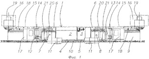
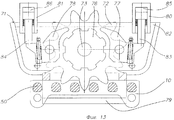
Представленный на фиг.1 известной конструкции комбайн (Горбатов П.А. и др. Горные машины для подземной добычи угля: учебное пособие для вузов. Донецк: Норд Компьютер, 2006, стр.242) имеет корпус 1 с размещенными в нем электрическим блоком 2 и гидравлическим блоком 3 с пультами 4 и 5 для управления ими. В камерах 6 корпуса 1 установлены левый и правый механизмы 7, 8 для поступательного перемещения комбайна относительно лавного конвейера 9, который с завальной стороны оснащен цевочной рейкой 10. В зацеплении с этой цевочной рейкой 10 постоянно находятся цевочные колеса 11 механизмов 7 и 8 для поступательного перемещения комбайна по конвейеру 9.The combine shown in Fig. 1 of a well-known design (Gorbatov P.A. et al. Mining machines for underground coal mining: a study guide for universities. Donetsk: Nord Computer, 2006, p. 242) has a building 1 with an
На левом и правом торцах 12, 13 корпуса 1 комбайна с помощью шарниров 14 присоединены поворотные в вертикальной плоскости комбайна рукояти 15, несущие исполнительный орган 16 с горизонтальной осью вращения для отбойки полезного ископаемого, оснащенный обычно зубковым режущим инструментом. Исполнительные органы 16 приводятся во вращение от расположенных внутри рукоятей 15 электродвигателя 17 и редуктора 18, соединенного своим выходным валом 19 с исполнительным органом 16.At the left and right ends 12, 13 of the combine body 1, by means of
Каждый из механизмов 7, 8 для поступательного перемещения комбайна по конвейеру 9 снабжен тормозом 20, который служит для неподвижного удержания (фиксации) комбайна на конвейере 9, когда электродвигатели 21 механизмов 7, 8 отключены.Each of the
Применяемые в известном комбайне исполнительные органы 16 выполнены в виде вращающегося вокруг горизонтальной оси шнека, оснащенного зубковым режущим инструментом, позволяющим достаточно эффективно разрушать полезные ископаемые и встречающиеся породные включения твердостью до f=8 (по Протодьяконову).The
Нежелательные проблемы, как отмечалось ранее, возникают при встрече в пласте полезного ископаемого породных включений крепостью f>8, когда продуктивная работа по выемке горной массы резко уменьшается.Undesirable problems, as noted earlier, arise when rock inclusions meet a strength of f> 8 when the productive work of excavating the rock mass sharply decreases.
Для повышения эффективности работы комбайна при разработке угольных пластов с породными включениями крепостью f>8 предлагается усовершенствованный согласно изобретению комбайн, один из вариантов исполнения которого показан на фиг.2-5.To improve the efficiency of the harvester in the development of coal seams with rock inclusions with a strength of f> 8, an improved combine harvester according to the invention is proposed, one embodiment of which is shown in FIGS. 2-5.
Комбайн в соответствии с изобретением также имеет корпус 22, где размещены электрический блок 2 и гидравлический блок 3 и их пульты 4, 5 управления, левый и правый механизмы 7, 8 для поступательного перемещения комбайна по лавному конвейеру 9, который несет расположенную с завальной стороны цевочную рейку 10, взаимодействующую с цевочным колесом 11 механизмов 7, 8 для поступательного перемещения комбайна.The harvester in accordance with the invention also has a
Комбайн оснащен двумя поворотными в вертикальной его плоскости рукоятями 15 с исполнительными органами 16 и 23 с горизонтальной осью вращения, где исполнительный орган 23 предназначен для разрушения породных включений крепостью f>8, встречающихся внутри разрабатываемого пласта угля, и может быть оснащен режущим инструментом шарошечного типа.The harvester is equipped with two
В отличие от известного комбайна, раскрытого выше, в комбайне по изобретению для его продуктивной работы по крепким породным включениям между корпусом 22 и рукоятью 15 с исполнительным органом 23 установлен механизм 24 для подачи этой рукояти на забой при разрушении породных включений, при этом комбайн снабжен устройством 25 для удержания его неподвижно на конвейере 9 при отбойке исполнительным органом 23 породных включений с целью повышения устойчивости комбайна при ограниченной массе корпуса 22 и повышенных параметрах вибрации при отбойке породных включений.In contrast to the known combine disclosed above, in the combine according to the invention for its productive work on strong rock inclusions between the
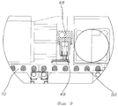
Механизм 24 для подачи рукояти 15 с исполнительным органом 23 включает в себя гидравлический домкрат 26, цилиндр которого 27 шарниром 28 соединен с корпусом 22, а шток 29 шарниром 30 соединен с кареткой 31, размещенной на дополнительном корпусе 32. Последний разъемным резьбовым соединением 33 сочленен с левым торцом 34 основного корпуса 22. При этом каретка 31 установлена на дополнительном корпусе 32 с помощью наружных направляющих пазов 35 на его боковых стенках и внутренних выступов 36 на стенках каретки 31. Более подробно это можно видеть на фиг.8. Благодаря такому выполнению каретка 31 может совершать возвратно-поступательные перемещения по продольной оси комбайна относительно дополнительного корпуса 32 от гидравлического домкрата 26.The
Рукоять 15 с исполнительным органом 16 шарнирами 37 соединена с правым торцом основного корпуса 22 и для ее поворота в вертикальной плоскости служит домкрат 38, прикрепленный своим цилиндром 39 к основному корпусу 22 шарниром 40, а штоком 41 - к рукояти 15 шарниром 42.The
Для поворота рукояти 15 с исполнительным органом 23 в вертикальной плоскости предназначен гидравлический домкрат 43, цилиндр 44 которого шарниром 45 закреплен на каретке 31, а шток шарниром 46 - на рукояти 15.To rotate the
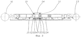
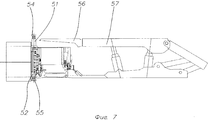
Устройство 25 для удержания неподвижно (фиксации) комбайна на конвейере 9 включает в себя две распорные в кровлю и почву пласта гидравлические стойки 47, закрепленные на забойной стороне основного корпуса 22 комбайна, и два распорных относительно цевочной рейки 10 конвейера 9 гидравлических фиксатора 48, закрепленных на завальной стороне основного корпуса 22 комбайна и входящих своими башмаками 49 в зацепление с цевками 50 цевочной рейки 10 конвейера. Более ясно о работе и принципе действия гидравлических фиксаторов 48 можно судить по фиг.9 и 10.The
Как видно на фиг.2, 6 и 7, распорные гидравлические стойки 47 имеют верхнюю и нижнюю части, то есть верхний шток 51 и нижний шток 52, а также общую поршневую полость 53 (фиг.5), причем верхние штоки 51 соединены между собой опорной накладкой 54, взаимодействующей с кровлей пласта, а нижние штоки 52 соединены между собой опорной накладкой 55, взаимодействующей с почвой пласта. Верхние штоки 51 и соединяющая их накладка 54 размещены в зазоре между грудью забоя и передней кромкой консоли 56 верхнего перекрытия 57 крепи, а нижние штоки 52 и соединяющая их накладка 55 размещены в зазоре между грудью забоя и кромкой зачистного лемеха 58 конвейера 9.As can be seen in FIGS. 2, 6 and 7, the hydraulic spacers 47 have upper and lower parts, that is, an
Как показано на фиг.8, внутри дополнительного корпуса 32 размещены гидравлический насос 59 и гидравлический бак 60, параллельно включенные в гидравлическую систему (не показана) гидравлического блока, находящуюся в основном корпусе 22 комбайна. Насос 59 в этом случае может работать в качестве резервного при отказе по какой-либо причине насоса гидравлического блока 3.As shown in Fig. 8, a
Второй вариант исполнения комбайна, усовершенствованного в соответствии с изобретением, показан на фиг.11-14.A second embodiment of the harvester improved in accordance with the invention is shown in FIGS. 11-14.
В случае возникновения волнистой гипсометрии в вынимаемом пласте угля с породными включениями возникает необходимость с минимальными затратами переоборудовать в шахтных условиях комбайн в первом варианте исполнения в комбайн, приспособленный для работы в условиях волнистой гипсометрии. Этому требованию в полной мере отвечает далее описываемый комбайн.In the event of the occurrence of wavy hypsometry in a removable coal seam with rock inclusions, it becomes necessary to convert the mine harvester in the first embodiment into a combine adapted to work in conditions of wavy gypsometry at minimal cost. The harvester described below fully meets this requirement.
Для этого производят демонтаж распорных гидравлических стоек 47 с накладками 54, 55, входящих в конструкцию устройства 25 для неподвижного удержания комбайна на конвейере 9, камеры 6 с левым механизмом 7 для перемещения комбайна и каретки 31 с рукоятью 15, несущей исполнительный орган 23.To do this, dismantle the hydraulic spacers 47 with
Далее на направляющие пазы 35 дополнительного корпуса 32 устанавливается каретка 61 иного конструктивного выполнения, которое заключается в том, что на стенке каретки 61 с завальной стороны смонтировано своей осью 62 дополнительное цевочное колесо 63, входящее в зацепление с цевочной рейкой 10 конвейера 9, а с забойной стороны каретка 61 оснащается опорной лыжей 64, опирающейся на зачистной лемех 58 конвейера 9. Дополнительное цевочное колесо 63 оснащено захватом 65 (фиг.14), охватывающим цевочную рейку 10. Кроме того, на стенке каретки 61 с завальной стороны выполнены проушины 66 для шарнирного крепления штока 67 гидравлического домкрата 68, входящего в состав дополнительного механизма 69 для подачи рукояти 15 с исполнительным органом 23 на забой. Затем рукоять 15 с исполнительным органом 23 снова шарнирно соединяют уже с кареткой 61. К цилиндру 70 гидравлического домкрата 68 шарнирно присоединен отдельный корпус 71 (фиг.13), несущий опорное цевочное колесо 72, входящее в зацепление с цевочной рейкой 10 конвейера 9. При этом ось 73 опорного цевочного колеса 72 установлена в стенках 74, 75 отдельного корпуса 71, а на оси 73 надето и жестко связано с опорным цевочным колесом 72 храповое кольцо 76, взаимодействующее попеременно с одной из храповых собачек 77 или 78, которые закреплены в стенках отдельного корпуса 71 с возможностью поворота. Указанный отдельный корпус 71 снабжен захватом 79, охватывающим цевочную рейку 10 конвейера 9. Для управления храповыми собачками 77, 78 служат гидравлические патроны 80 и 81, размещенные на верхней крышке 82 отдельного корпуса 71. Штоки 83 и 84 этих гидравлических патронов 80 и 81 контактируют с хвостовиками соответствующих храповых собачек 77, 78. Попеременная работа гидравлических патронов 80, 81 и храповых собачек 77, 78 обусловлена изменением направления рабочего хода комбайна. При осуществлении маневровых операций, в том числе холостого перегона, обе храповые собачки 77, 78 выводятся с помощью гидравлических патронов 80, 81 из контакта с храповым кольцом 76, для чего поршневые полости 85 и 86 соединяются с напорной магистралью гидравлического блока 3 с пульта 5.Next, on the
Комбайн второго варианта конструктивного исполнения лучше приспосабливается к волнистой гипсометрии разрабатываемого пласта полезного ископаемого вследствие того, что после демонтажа камеры 6 с механизмом 7 становится короче по длине на 1,3-1,5 м комбайна первого варианта исполнения. В описанном варианте комбайна роль механизма для удержания выполняют гидравлические фиксаторы 48 и отдельный корпус 71 с опорным цевочным колесом 72, храповым кольцом 76 и храповыми собачками 77, 78.The harvester of the second embodiment is better adapted to the wavy hypsometry of the developed mineral layer due to the fact that after dismantling the
Следует также отметить, что раскрытый выше дополнительный механизм 69 для подачи рукояти 15 с исполнительным органом 23 может также успешно использоваться в комбайне в первом варианте исполнения с целью создания повышенного усилия подачи рукояти 15 с исполнительным органом 23. В этом случае шток 67 гидравлического домкрата 68, входящего в состав механизма 69, шарнирно закрепляется на стенке каретки 31, а отдельный корпус 71 размещается на цевочной рейке 10 между левым механизмом 7 для поступательного перемещения и рукоятью 15, несущей исполнительный орган 23 (данный вариант исполнения является альтернативным и не показан на фиг.11-14).It should also be noted that the
С созданием комбайнов вышеописанных конструкций становится возможным усовершенствовать способ выемки пластовых полезных ископаемых, в частности пластов угля с породными включениями крепостью f>8 на оптимальных условиях. Усовершенствование способа заключается, по существу, в использовании по меньшей мере одного из двух работающих в одной лаве комбайнов согласно изобретению с исполнительным органом, предназначенным для работы по крепким породным включениям, оборудованного механизмом для подачи этой рукояти на забой и устройством для удержания комбайна неподвижно при отбойке породных включений исполнительным органом.With the creation of combines of the above-described designs, it becomes possible to improve the method of mining reservoir minerals, in particular coal seams with rock inclusions with a strength of f> 8 under optimal conditions. The improvement of the method consists essentially in the use of at least one of the two combines working in the same lava according to the invention with an executive body designed to work on strong rock inclusions, equipped with a mechanism for feeding this handle to the face and a device for holding the combine motionless during breaking pedigree inclusions by the executive body.
Ниже приводится описание способа выемки пластов угля с комбайнами предложенной конструкции со ссылкой на фиг.15-17.The following is a description of the method of extraction of coal seams with combines of the proposed design with reference to Fig.15-17.
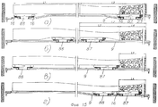
Схемы отработки лавы с различным расположением крепких породных включений по длине пласта представлены на фиг.15а, б, в, г.Lava mining schemes with different locations of strong rock inclusions along the length of the formation are presented in FIGS. 15a, b, c, d.
В исходном положении (фиг.15,а) комбайн 87 согласно изобретению находится у правого сопряжения и предназначен для выемки пласта на участке L2 с породными включениями длиной L4, его правая рукоять 15 оснащена исполнительным органом 23 для разрушения породных включений. Комбайн 88 известной конструкции находится у левого сопряжения и предназначен для выемки пласта на участке L1, в основном свободного от породных включений, и его рукояти 15 оснащены исполнительным органом 16 для отбойки угля.In the initial position (Fig. 15, a), the
Выемочный цикл обоих комбайнов начинается с зарубки в пласт косым заездом, при этом комбайн 87 так же как и комбайн 88 осуществляет зарубку в пласт на участке L3, свободном от породных включений.The excavation cycle of both combines begins with notching into the formation by an oblique run, while the
На фиг.15,б, в показаны комбайны 87 и 88 в процессе зарубки в пласт. После окончания зарубки в пласт комбайн 87 располагается непосредственно перед участком L4 породных включений, а комбайн 88 - у левого сопряжения лавы со штреком. Далее начинается рабочий ход, когда оба комбайна 87 и 88 движутся слева направо в одном направлении. Перед началом рабочего хода комбайна 87 включается устройство для его удержания в неподвижном положении на конвейере 9, после чего включается механизм для подачи рукояти с исполнительным органом 23. После выбора хода подачи гидравлического домкрата механизма для подачи рукояти выключается устройство для удержания комбайна 87 и включается механизм для поступательного перемещения комбайна 87. При этом происходит отбойка неразрушенной части пласта, оставшейся после прохода исполнительного органа 23, и погрузка отбитой горной массы на конвейер 9. В процессе работы механизма для перемещения комбайна гидравлический домкрат механизма для подачи рукояти складывается и комбайн 87 подготавливается к следующему циклу разрушения участка L4 породных включений на величину рабочего хода (800-1000 мм) гидравлического домкрата. Далее перечисленные выше операции рабочего хода повторяются до окончания цикла выемки на участке L4. После этого комбайн 87 на маневровой скорости возвращается в исходное положение, показанное на фиг.15,а. Комбайн 87 производит выемку угля на участке L1 по известной челноковой схеме.On Fig, b, c shows the
В случае смещения породных включений в пласте к левому сопряжению, как это показано на фиг.16, производят переоборудование комбайнов 87 и 88: комбайн 87 переоборудуют в обычное исполнение, как комбайн 88, а комбайн 87 переоборудуют согласно изобретению. Теперь комбайн 88 работает на участке L5 подобно комбайну 87 на участке L2 (фиг.15,а), разрушая породные включения на участке L7, а комбайн 87 производит выемку полезного ископаемого на участке L6 по известной челноковой схеме.In the event that the rock inclusions in the formation are shifted to the left mate, as shown in Fig. 16, the
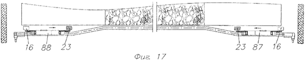
Если породные включения проявляются в средней части лавы, как показано на фиг.17, оба комбайна 87 и 88 оборудуются в соответствии с изобретением. При этом в случае отработки породных включений комбайны 87 и 88 работают по односторонней схеме с движением в рабочем режиме навстречу один другому, а при выемке полезного ископаемого на участках, свободных от породных включений, - по челноковой схеме с зарубкой по полезному ископаемому, то есть по углю.If rock inclusions occur in the middle of the lava, as shown in FIG. 17, both combines 87 and 88 are equipped in accordance with the invention. In this case, in the case of mining the rock inclusions, the
В том случае, когда мощность породных включений больше наружного диаметра исполнительного органа 23, второй исполнительный орган 16 также может быть заменен на исполнительный орган 23. При этом погрузка отбитой горной массы в основном производится зачистным лемехом конвейера 9 в процессе его передвижки на новую дорогу.In the case when the power of the rock inclusions is greater than the outer diameter of the
Описанные здесь варианты конструктивных исполнений комбайнов могут подвергаться отдельным модификациям в рамках предлагаемой ниже формулы изобретения.The embodiments of the combines described here may undergo separate modifications within the scope of the claims below.
Claims (16)
Priority Applications (1)
| Application Number | Priority Date | Filing Date | Title |
|---|---|---|---|
| RU2008110870/03A RU2362876C2 (en) | 2008-03-24 | 2008-03-24 | Miner for excavation of minerals and procedure for their excavation |
Applications Claiming Priority (1)
| Application Number | Priority Date | Filing Date | Title |
|---|---|---|---|
| RU2008110870/03A RU2362876C2 (en) | 2008-03-24 | 2008-03-24 | Miner for excavation of minerals and procedure for their excavation |
Publications (2)
| Publication Number | Publication Date |
|---|---|
| RU2008110870A RU2008110870A (en) | 2009-04-10 |
| RU2362876C2 true RU2362876C2 (en) | 2009-07-27 |
Family
ID=41014621
Family Applications (1)
| Application Number | Title | Priority Date | Filing Date |
|---|---|---|---|
| RU2008110870/03A RU2362876C2 (en) | 2008-03-24 | 2008-03-24 | Miner for excavation of minerals and procedure for their excavation |
Country Status (1)
| Country | Link |
|---|---|
| RU (1) | RU2362876C2 (en) |
Cited By (4)
| Publication number | Priority date | Publication date | Assignee | Title |
|---|---|---|---|---|
| RU2467167C1 (en) * | 2011-05-19 | 2012-11-20 | Анатолий Андреевич Алькема | Shuttle coal cutter machine |
| RU2623381C2 (en) * | 2011-12-19 | 2017-06-26 | ДЖОЙ ЭмЭм ДЕЛАВЭР, ИНК. | Connected coal-cutting device |
| RU2661830C1 (en) * | 2017-09-27 | 2018-07-20 | Николай Андреевич Ковалев | Mining combine |
| RU2673683C1 (en) * | 2015-06-22 | 2018-11-29 | Сандвик Интеллекчуал Проперти Аб | Cutting unit with cutting device and method of assembly |
Families Citing this family (1)
| Publication number | Priority date | Publication date | Assignee | Title |
|---|---|---|---|---|
| CN107008560B (en) * | 2017-05-04 | 2023-10-20 | 江苏华宏科技股份有限公司 | Reinforced concrete beam pre-crushing device |
-
2008
- 2008-03-24 RU RU2008110870/03A patent/RU2362876C2/en not_active IP Right Cessation
Cited By (4)
| Publication number | Priority date | Publication date | Assignee | Title |
|---|---|---|---|---|
| RU2467167C1 (en) * | 2011-05-19 | 2012-11-20 | Анатолий Андреевич Алькема | Shuttle coal cutter machine |
| RU2623381C2 (en) * | 2011-12-19 | 2017-06-26 | ДЖОЙ ЭмЭм ДЕЛАВЭР, ИНК. | Connected coal-cutting device |
| RU2673683C1 (en) * | 2015-06-22 | 2018-11-29 | Сандвик Интеллекчуал Проперти Аб | Cutting unit with cutting device and method of assembly |
| RU2661830C1 (en) * | 2017-09-27 | 2018-07-20 | Николай Андреевич Ковалев | Mining combine |
Also Published As
| Publication number | Publication date |
|---|---|
| RU2008110870A (en) | 2009-04-10 |
Similar Documents
| Publication | Publication Date | Title |
|---|---|---|
| RU2362876C2 (en) | Miner for excavation of minerals and procedure for their excavation | |
| RU2645017C2 (en) | Mining machine (versions), method for developing material of drift wall and disc cutter | |
| RU2603147C2 (en) | Mining plant for extraction of mineral materials, lying in the form of formations or arrays and tunneling combine | |
| EP2348189B1 (en) | Mining machine with driven disc cutters | |
| CN204283425U (en) | Digger | |
| CN103452562A (en) | Mining multifunctional milling and drilling machine | |
| WO2007075149A1 (en) | Tunnel driving machine with horseshoe-shaped transverse profile | |
| JPH06117187A (en) | Shield excavator | |
| CN107654229B (en) | Large-mining-height shearer-preventing coal cutter | |
| CN104564076B (en) | Caterpillar band walking type double-barrel coal cutter for strip mine | |
| CN216517999U (en) | Hard rock cantilever tunneling machine | |
| CN105386760B (en) | Hydraulic control is taken a step quartering hammer digger | |
| CN109882189A (en) | A kind of half section shield machine of the shape of a hoof and construction method suitable for fault belt | |
| RU2368780C1 (en) | Combine for selective concavity of thin stratums of minerals | |
| CN108590686A (en) | Automatically replaceable modular cutting tool assembly | |
| CN104929177B (en) | A kind of pavement breaking excavates integrated hydraulic scraper bowl | |
| CN210003277U (en) | tunnel working device with jumbolter at tail | |
| RU2710044C2 (en) | Conveyor pan | |
| RU2309238C1 (en) | Device for roof-bolt borehole drilling by fluid-circulation method | |
| RU102043U1 (en) | ROTARY DRILLING RIG FOR DRILLING HORIZONTAL DRAINAGE WELLS | |
| JP3649536B2 (en) | Cutter head and tunnel excavator | |
| CN203430521U (en) | Mining multifunctional milling and drilling machine | |
| CN214787195U (en) | A vibroflotation device for cutting rock | |
| CN217270300U (en) | Single-side coal seam slotting equipment | |
| CN115992712A (en) | Main beam hinging middle-mounted structure of mining TBM |
Legal Events
| Date | Code | Title | Description |
|---|---|---|---|
| MM4A | The patent is invalid due to non-payment of fees |
Effective date: 20140325 |