RU2361237C2 - Method of photo-location measurement of height of cloud layers and device to this end - Google Patents
Method of photo-location measurement of height of cloud layers and device to this end Download PDFInfo
- Publication number
- RU2361237C2 RU2361237C2 RU2007130394/28A RU2007130394A RU2361237C2 RU 2361237 C2 RU2361237 C2 RU 2361237C2 RU 2007130394/28 A RU2007130394/28 A RU 2007130394/28A RU 2007130394 A RU2007130394 A RU 2007130394A RU 2361237 C2 RU2361237 C2 RU 2361237C2
- Authority
- RU
- Russia
- Prior art keywords
- photodetector
- pulse
- output
- strobe
- time
- Prior art date
Links
- 238000005259 measurement Methods 0.000 title claims abstract description 18
- 238000000034 method Methods 0.000 title claims abstract description 11
- 238000012545 processing Methods 0.000 claims abstract description 23
- 239000000523 sample Substances 0.000 claims description 38
- 230000005855 radiation Effects 0.000 claims description 15
- 230000003287 optical effect Effects 0.000 claims description 8
- 238000011084 recovery Methods 0.000 claims description 3
- 230000015572 biosynthetic process Effects 0.000 claims description 2
- 230000004044 response Effects 0.000 claims description 2
- 238000006073 displacement reaction Methods 0.000 claims 1
- 239000000126 substance Substances 0.000 abstract 1
- 230000001960 triggered effect Effects 0.000 description 3
- 238000001514 detection method Methods 0.000 description 2
- 238000012544 monitoring process Methods 0.000 description 2
- 206010047700 Vomiting Diseases 0.000 description 1
- 239000000443 aerosol Substances 0.000 description 1
- 239000005427 atmospheric aerosol Substances 0.000 description 1
- 230000005540 biological transmission Effects 0.000 description 1
- 238000002485 combustion reaction Methods 0.000 description 1
- 238000013500 data storage Methods 0.000 description 1
- 230000007423 decrease Effects 0.000 description 1
- 238000010586 diagram Methods 0.000 description 1
- 238000002592 echocardiography Methods 0.000 description 1
- 230000004907 flux Effects 0.000 description 1
- 239000000446 fuel Substances 0.000 description 1
- 230000003993 interaction Effects 0.000 description 1
- 238000007726 management method Methods 0.000 description 1
- 230000000737 periodic effect Effects 0.000 description 1
- 230000000630 rising effect Effects 0.000 description 1
- 238000007619 statistical method Methods 0.000 description 1
- 230000001360 synchronised effect Effects 0.000 description 1
- 230000008673 vomiting Effects 0.000 description 1
Images
Classifications
-
- Y—GENERAL TAGGING OF NEW TECHNOLOGICAL DEVELOPMENTS; GENERAL TAGGING OF CROSS-SECTIONAL TECHNOLOGIES SPANNING OVER SEVERAL SECTIONS OF THE IPC; TECHNICAL SUBJECTS COVERED BY FORMER USPC CROSS-REFERENCE ART COLLECTIONS [XRACs] AND DIGESTS
- Y02—TECHNOLOGIES OR APPLICATIONS FOR MITIGATION OR ADAPTATION AGAINST CLIMATE CHANGE
- Y02A—TECHNOLOGIES FOR ADAPTATION TO CLIMATE CHANGE
- Y02A90/00—Technologies having an indirect contribution to adaptation to climate change
- Y02A90/10—Information and communication technologies [ICT] supporting adaptation to climate change, e.g. for weather forecasting or climate simulation
Landscapes
- Optical Radar Systems And Details Thereof (AREA)
- Investigating Or Analysing Materials By Optical Means (AREA)
Abstract
Description
Изобретения относятся к приборостроению, а именно к технике измерения оптических характеристик атмосферы с целью определения высоты обнаружения взлетно-посадочной полосы и мониторинга аэрозольного следа, образованного продуктами сгорания топлива летательных аппаратов, в интересах обеспечения безопасности полетов авиации.The invention relates to instrumentation, and in particular to a technique for measuring the optical characteristics of the atmosphere in order to determine the height of detection of the runway and monitoring the aerosol trail formed by the combustion products of aircraft fuel, in the interest of ensuring aviation safety.
Широкое распространение в отечественной и зарубежной практике получили светолокационные измерители высоты облаков, использующие в качестве излучателя светодиоды и лазеры. Такие приборы имеют большую дальность обнаружения нижней границы облаков благодаря высокой мощности излучения и накопления данных за один или несколько импульсов. Однако в случае, когда вероятность регистрации эхо-сигнала становится меньше единицы, например сигнала от второго слоя облаков после потерь на рассеяние энергии импульса при двукратном прохождении первого слоя, эхо-сигнал не регистрируется [Круглов Р.А. Статистический метод обнаружения низкой облачности в системе автоматизированного метеообеспечения аэродромов. Труды ГГО, выпуск 413, 1980]. Известно также устройство по патенту RU №2136016, МПК G01S 17/95, опубликованному в 1999 г., для измерения высоты нижней границы облаков, которое содержит источник зондирующих импульсов, фотоприемник, оптическую систему, формирователь запускающих импульсов, хронизатор, блок обработки эхо-сигналов и измеритель временных интервалов. Данное устройство обладает следующими недостатками.Widespread in domestic and foreign practice are radar-based cloud height meters using LEDs and lasers as emitters. Such devices have a large range of detection of the lower boundary of the clouds due to the high radiation power and data storage for one or more pulses. However, in the case when the probability of detecting an echo signal becomes less than unity, for example, a signal from a second layer of clouds after losses on the dissipation of pulse energy during a double passage of the first layer, the echo signal is not recorded [Kruglov R.A. A statistical method for detecting low clouds in an automated weather monitoring system for aerodromes. Proceedings of the GGO, issue 413, 1980]. A device is also known according to patent RU No. 2136016, IPC G01S 17/95, published in 1999, for measuring the height of the lower boundary of the clouds, which contains a probe pulse source, a photodetector, an optical system, a trigger pulse shaper, a chronizer, an echo signal processing unit and a time slot meter. This device has the following disadvantages.
1. Невозможность измерения измерений характеристик многослойных облаков (плотности и толщины слоя облаков).1. The inability to measure measurements of the characteristics of multilayer clouds (density and thickness of the cloud layer).
2. Сложность электронной схемы для приема и обработки эхо-сигнал.2. The complexity of the electronic circuit for receiving and processing an echo signal.
3. Требуется большое количество замеров для компенсации неточности получения результатов обработки при применении порядковой статистики, так как уровень эхо-сигналов зависит от дальности.3. A large number of measurements are required to compensate for the inaccuracy of obtaining processing results when applying ordinal statistics, since the level of echo signals depends on the range.
Наиболее близким к предлагаемому изобретению, относящемуся к способу светолокационного измерения высоты облачных слоев, является способ, описанный в статье А.В.Бухарина, С.М.Першина «Теоретическое рассмотрение лидара обратного рассеяния с безопасным для глаз уровнем излучения». Оптика атмосферы и океана, т.7, стр.521-537 (1994 г.), заключающийся в направлении зондирующих импульсов света к облачным слоям и включении фотоприемника излучения строб-импульсом питания, в течение которого может произойти только одно срабатывание фотоприемника, приеме эхо-сигнала, срабатывании фотоприемника, передаче значения задержки времени между зондирующим импульсом и срабатыванием фотоприемника в блок управления и обработки сигналов, где находятся ячейки памяти, причем строб разделяется на целое число равных по величине временных интервалов, и каждому временному интервалу соответствует своя ячейка памяти. При приеме эхо-сигналов в ячейку памяти, соответствующую временному интервалу строба, в который произошло это событие, поступает единичный импульс, то есть содержимое этой ячейки памяти увеличивается на единицу. Прием эхо-сигнала с другой временной задержкой будет увеличивать на единицу содержимое другой, соответствующей этой временной задержке, ячейки памяти. Причем, в случае слабых фоновых потоков и эхо-сигнала, фотоприемник может не регистрировать эти сигналы. В этом случае содержимое ячеек памяти остается без изменения. После чего содержимое ячеек памяти считывается и передается в компьютер, который формирует гистограмму распределения числа приема эхо-сигналов фотоприемником по номерам ячеек памяти и, следовательно, по дальности расположения облачных слоев-источников эхо-сигналов в данном стробе. Затем строб перемещается на фиксированную задержку, равную или меньшую длительности строба, относительно первого светового импульса зондирования и цикл измерения повторяется. Число смещений строба определяется дальностью зондирования. Причем (уровень) фонового потока (шума) измеряется отдельно, для чего импульс строба подается на приемник также в середине интервала между световыми импульсами. Таким образом, компьютер формирует две гистограммы распределения числа приема эхо-сигналов фотоприемником по номерам ячеек, одна из которых отражает распределение «сигнал + шум», а другая - только «шум». Полная гистограмма по всей трассе зондирования составляется как последовательность отдельных гистограмм, измеренных в каждом положении строба при его «сшивке» на границе совмещения. Гистограмма распределения эхо-сигнала получается вычитанием гистограмм «сигнал + шум» - «шум».Closest to the proposed invention relating to the method of radar measurement of the height of the cloud layers is the method described in the article by A. V. Bukharin, S. M. Pershin “Theoretical consideration of backscattering lidar with an eye-safe radiation level”. Optics of the atmosphere and ocean, vol. 7, pp. 521-537 (1994), which consists in the direction of the probing light pulses to the cloud layers and the photodetector is turned on by a strobe-power pulse, during which only one photodetector operation can occur, receiving an echo -signal, the operation of the photodetector, the transmission of the delay time between the probe pulse and the operation of the photodetector to the control and signal processing unit, where the memory cells are located, and the strobe is divided by an integer equal to the value of time interactions vomiting, and each time interval has its own memory cell. When echoes are received, a single pulse is received in the memory cell corresponding to the time interval of the strobe in which this event occurred, that is, the contents of this memory cell are increased by one. Reception of an echo signal with a different time delay will increase by one the contents of another memory cell corresponding to this time delay. Moreover, in the case of weak background flows and an echo signal, the photodetector may not register these signals. In this case, the contents of the memory cells remain unchanged. After that, the contents of the memory cells are read and transferred to a computer, which generates a histogram of the distribution of the number of echo signals received by the photodetector according to the numbers of memory cells and, therefore, according to the range of cloud layers of the source of echo signals in this strobe. Then, the strobe moves for a fixed delay equal to or less than the strobe duration relative to the first light pulse of the probe and the measurement cycle is repeated. The number of strobe offsets is determined by the sensing range. Moreover, the (level) background flux (noise) is measured separately, for which the strobe pulse is supplied to the receiver also in the middle of the interval between light pulses. Thus, the computer generates two histograms of the distribution of the number of echo signals received by the photodetector according to the cell numbers, one of which reflects the “signal + noise” distribution, and the other only “noise”. A complete histogram along the entire sensing path is compiled as a sequence of individual histograms measured at each position of the strobe when it is “stitched” at the alignment border. A histogram of the distribution of the echo signal is obtained by subtracting the histograms "signal + noise" - "noise".
Светолокационный измеритель высоты нижней границы облачных слоев для осуществления данного способа содержит источник зондирующих импульсов, на вход которого подается запускающий импульс с выхода формирователя запускающих импульсов. Один выход источника зондирующих импульсов связан с входом синхронизатора, а со второго выхода подается зондирующий импульс к облачным слоям. Вход фотоприемника с помощью оптической схемы, обеспечивающей требуемую геометрию диаграмм направленности, связан с выходом источника зондирующих импульсов через облачный слой. Выход синхронизатора связан с первыми входами измерителя временных интервалов и блока управления и обработки данных. Один выход которого является входом формирователя стробов, выход которого, в свою очередь, связан с приемником излучения. Выход приемника излучения связан с формирователем импульсов, выход которого является вторым входом измерителя временных интервалов, а его выход является вторым входом блока управления и обработки сигналов. Выход блока управления и обработки сигналов является выходом всего устройства.The light-radar height meter of the lower boundary of the cloud layers for the implementation of this method contains a probe pulse source, the input of which is supplied with a trigger pulse from the output of the trigger pulse shaper. One output of the probe pulse source is connected to the synchronizer input, and a probe pulse is supplied to the cloud layers from the second output. The input of the photodetector using an optical circuit that provides the desired geometry of the radiation patterns is connected with the output of the probe pulse source through the cloud layer. The synchronizer output is connected to the first inputs of the time interval meter and the control and data processing unit. One output of which is the input of the gate driver, the output of which, in turn, is connected to the radiation receiver. The output of the radiation receiver is connected to a pulse shaper, the output of which is the second input of the time interval meter, and its output is the second input of the control and signal processing unit. The output of the control and signal processing unit is the output of the entire device.
Но данные способ и устройство имеютBut the data method and device have
- низкую эффективность использования энергии излученного импульса, так как на каждый излученный зондирующий импульс получается не более одного срабатывания фотоприемника;- low efficiency of using the energy of the emitted pulse, since for each radiated probe pulse, no more than one operation of the photodetector is obtained;
- необходимость получения нескольких отдельных гистограмм, которые потом «сшиваются» в полную гистограмму;- the need to obtain several separate histograms, which are then “stitched” into a complete histogram;
- переменную вероятность срабатывания фотоприемника в течение строба, так как вероятность приема эхо-сигнала фотоприемником зависит от номера ячейки - чем ближе к концу, тем вероятность ниже и падает в зависимости от уровня сигнала, если фотоприемник сработал в начале строба и выключился, то потом он уже не будет регистрировать фотоны.- the variable probability of the photodetector being triggered during the strobe, since the probability of receiving an echo signal by the photodetector depends on the cell number - the closer to the end, the lower the probability and decreases depending on the signal level, if the photodetector worked at the beginning of the strobe and turned off, then it will no longer register photons.
Задачей данного изобретения является повышение эксплуатационных характеристик.The objective of the invention is to improve performance.
Технический результат - увеличение эффективности использования энергии зондирующего импульса при увеличении вероятности приема эхо-сигнала фотоприемником и упрощении обработки сигналов.The technical result is an increase in the energy efficiency of the probe pulse with an increase in the probability of receiving an echo signal by a photodetector and simplification of signal processing.
Это достигается тем, что в способе светолокационного измерения высоты облачных слоев, заключающемся в направлении зондирующих импульсов света к облачным слоям, включении фотоприемника излучения первым строб-импульсом питания одновременно с первым зондирующим импульсом, в течение которого может произойти только одно срабатывание фотоприемника, приеме эхо-сигнала, определении времени задержки между зондирующим импульсом и срабатыванием фотоприемника, направлении в момент срабатывания фотоприемника единичного импульса в ячейку памяти, соответствующую времени срабатывания фотоприемника, смещении каждого последующего строба-импульса питания фотоприемника, повторении измерений, суммировании единичных импульсов в соответствующих ячейках памяти и передаче данных на компьютер для построения гистограммы, в отличие от известного, фотоприемник во время строба периодически включается и выключается, причем время выключения равно или больше времени восстановления фотоприемника, а каждый последующий строб смещают на величину, равную времени между началом первого зондирующего импульса и последовательно каждым следующим выключением фотоприемника в первом стробе-импульсе питания строба, при этом число смещений равно отношению длительности выключения фотоприемника в стробе к длительности строба и при завершении измерений - формирование в ячейках памяти гистограммы - распределение числа единичных импульсов по времени задержки относительно зондирующего светового импульса по всей длине зондируемого пространства.This is achieved by the fact that in the method of radar measurement of the height of the cloud layers, which consists in the direction of the probe light pulses to the cloud layers, the radiation photodetector is turned on by the first strobe power pulse at the same time as the first probe pulse, during which only one photodetector operation can occur, the echo reception the signal, determining the delay time between the probe pulse and the operation of the photodetector, the direction at the time of the operation of the photodetector of a single pulse in the memory cell and, corresponding to the response time of the photodetector, the offset of each subsequent strobe-pulse of the power supply of the photodetector, repeating measurements, summing up individual pulses in the corresponding memory cells and transmitting data to a computer for building a histogram, in contrast to the known one, the photodetector periodically turns on and off during the strobe, and the off time is equal to or greater than the recovery time of the photodetector, and each subsequent strobe is shifted by an amount equal to the time between the beginning of the first probe of the receiving pulse and successively each subsequent shutdown of the photodetector in the first strobe-power pulse of the strobe, with the number of shifts equal to the ratio of the shutdown time of the photodetector in the strobe to the strobe duration and upon completion of measurements — formation of a histogram in the memory cells — distribution of the number of unit pulses over the delay time relative to the probe light pulse along the entire length of the probed space.
Кроме того, это достигается тем, что в устройстве для осуществления данного способа, состоящем из источника зондирующих импульсов, вход которого связан с выходом формирователя запускающих импульсов, один его выход связан с входом синхронизатора, а второй выход оптически сопряжен через оптическую систему с входом фотоприемника излучения, выход синхронизатора связан с первыми входами измерителя временных интервалов и блока управления и обработки данных, один выход которого является входом формирователя стробов, выход которого, в свою очередь, связан с фотоприемником излучения, выход фотоприемника излучения связан с формирователем импульсов, выход которого является вторым входом измерителя временных интервалов, а его выход является вторым входом блока управления и обработки сигналов, выход блока управления и обработки сигналов является выходом всего устройства, в отличие от известного, дополнительно введен многоканальный сумматор, первый вход которого связан с входом синхронизатора, второй вход с выходом измерителя временных интервалов, а выход со вторым входом блока управления и обработки данных.In addition, this is achieved by the fact that in the device for implementing this method, consisting of a probe pulse source, the input of which is connected to the output of the driver of the triggering pulses, one of its output is connected to the input of the synchronizer, and the second output is optically coupled through the optical system to the input of the radiation photodetector , the synchronizer output is connected to the first inputs of the time interval meter and the control and data processing unit, one output of which is the input of the gate generator, the output of which, in its own right The front is connected to the radiation photodetector, the output of the radiation photodetector is connected to a pulse shaper, the output of which is the second input of the time interval meter, and its output is the second input of the control and signal processing unit, the output of the control and signal processing unit is the output of the entire device, unlike known, an additional multi-channel adder is introduced, the first input of which is connected to the synchronizer input, the second input with the output of the time interval meter, and the output with the second input unit but management and data processing.
Предлагаемые изобретения иллюстрируются чертежами, на которых изображеныThe invention is illustrated by drawings, which depict
на фиг.1 - блок-схема устройства;figure 1 is a block diagram of a device;
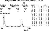
на фиг.2 - гистограмма.figure 2 is a histogram.
Предлагаемый способ по данному изобретению осуществляют в следующей последовательности: в направлении зондирующих импульсов света к облачным слоям, включением фотоприемника первым стробом-импульсом питания одновременно с первым зондирующим импульсом, причем в стробе происходит последовательное включение и выключение фотоприемника излучения и в течение каждого строба может произойти только одно срабатывание фотоприемника, приеме эхо-сигнала, срабатывании фотоприемника, передачи значения задержки времени между зондирующим импульсом и регистрацией эхо-сигнала в многоканальный сумматор и далее в блок управления и обработки сигналов, где находятся ячейки памяти, причем каждый строб представляет собой последовательность импульсов, интервал между которыми выбирается равным или большим времени восстановления фотоприемника после регистрации эхо-сигнала, а число импульсов определяется дальностью зондирования, и каждому импульсу соответствует своя ячейка памяти. При срабатывании фотоприемника в ячейку памяти, номер которой соответствует номеру импульса в стробе, при котором произошло это событие, поступает единичный импульс то есть содержимое этой ячейки памяти увеличивается на единицу. Регистрация эхо-сигнала в другой временной интервал будет увеличивать на единицу содержимое другой соответствующей этой временной задержке ячейки памяти. Причем в случае слабых фоновых потоков и эхо-сигнала, фотоприемник может не регистрировать эти сигналы. В этом случае содержимое ячеек памяти остается без изменения. Далее происходит смещение второго строба-импульса питания на величину, равную времени между началом первого зондирующего импульса и окончанием включения фотоприемника первым импульсом в первом стробе-импульсе питания. Повторение измерений, заполнение соответствующих ячеек памяти, вновь смещение строба-импульса питания на величину, равную времени между началом первого зондирующего импульса и окончанием включения фотоприемника вторым импульсом питания. Число смещений периодической последовательности импульсов в стробе питания фотоприемника определяется отношением длительности интервала между импульсами в стробе к длительности строба.The proposed method according to this invention is carried out in the following sequence: in the direction of the probe light pulses to the cloud layers, the photodetector is turned on by the first strobe-power pulse simultaneously with the first probe pulse, moreover, the radiation photodetector is turned on and off sequentially and during each strobe only one operation of the photodetector, receiving an echo signal, triggering a photodetector, transmitting the time delay value between the probe pulse ohm and registering the echo signal to the multi-channel adder and then to the control and signal processing unit where the memory cells are located, each strobe representing a sequence of pulses, the interval between which is chosen equal to or greater than the recovery time of the photodetector after the echo signal is recorded, and the number of pulses determined by the sensing range, and each pulse has its own memory cell. When the photodetector is triggered, a single pulse is received in the memory cell whose number corresponds to the pulse number in the strobe at which this event occurred, that is, the contents of this memory cell are increased by one. Registration of an echo signal in a different time interval will increase by one the contents of another cell corresponding to this time delay. Moreover, in the case of weak background flows and an echo signal, the photodetector may not register these signals. In this case, the contents of the memory cells remain unchanged. Next, the second strobe-power pulse is shifted by an amount equal to the time between the beginning of the first probing pulse and the end of the photodetector's turn-on by the first pulse in the first strobe-power pulse. Repeating measurements, filling in the corresponding memory cells, again shifting the strobe-power pulse by an amount equal to the time between the beginning of the first probing pulse and the end of the photodetector turning on with the second power pulse. The number of shifts of the periodic sequence of pulses in the power gate of the photodetector is determined by the ratio of the duration of the interval between pulses in the strobe to the duration of the strobe.
После завершения последнего цикла измерения в ячейках памяти формируется распределение числа единичных импульсов по времени задержки относительно зондирующего светового импульса. Это распределение передается на компьютер для отображения и хранения.After completion of the last measurement cycle, a distribution of the number of unit pulses over the delay time relative to the probing light pulse is formed in the memory cells. This distribution is transferred to a computer for display and storage.
Предлагаемый светолокационный измеритель высоты нижней границы облачных слоев (на фиг.1) содержит излучатель зондирующих импульсов 1 и фотоприемник 2, оптическую систему 3, формирователь запускающих импульсов 4, синхронизатор 5, формирователь импульсов 6, измеритель временных интервалов 7, формирователь стробов и сдвига стробов 8, схему управления и обработки сигналов 9, многоканальный сумматор 10. На вход источника зондирующих импульсов 1 подается запускающий импульс с выхода формирователя запускающих импульсов 4. Один выход источника зондирующих импульсов 1 связан с входом синхронизатора 5, а со второго выхода подается зондирующий импульс к облачным слоям. Вход фотоприемника 2 с помощью оптической схемы 3, обеспечивающей требуемую геометрию диаграмм направленности, связан с выходом источника зондирующих импульсов 1 через облачный слой. Выход синхронизатора 5 связан с первыми входами измерителя временных интервалов 7, многоканального сумматора 10 и блока управления и обработки данных 9, первый выход которого является входом формирователя стробов 8, выход которого, в свою очередь, связан с фотоприемником 2. Выход фотоприемника 2 связан с формирователем импульсов 6, выход которого является вторым входом измерителя временных интервалов 7, а его выход является вторым входом многоканального сумматора 10. Выход многоканального сумматора 10 является входом блока управления и обработки сигналов 9. Выход блока управления и обработки сигналов 9 является выходом всего устройства.The proposed radar height meter of the lower boundary of the cloud layers (Fig. 1) contains a
Устройство работает следующим образом. Источник зондирующих импульсов 1 излучает короткие (~(5-100) нс) зондирующие импульсы света мощностью (~50 Вт) в направлении облачного слоя атмосферы. Период следования импульсов определяется формирователем запускающих импульсов 4 и лежит в диапазоне до 100 кГц. Синхронизатор 5 содержит фотодиод и формирует синхроимпульсы в моменты излучения зондирующих световых импульсов источником зондирующих импульсов 1, синхроимпульсы подаются на первый вход измерителя временных интервалов 7, запускают измеритель временных интервалов 7 и синхронизируют схему управления и обработки сигналов 9. Рассеянные атмосферным аэрозолем и облачными слоями эхо-сигналы возвращаются в фотоприемник 2. Оптическая система 3 обеспечивает требуемую геометрию диаграмм направленности излучателя и фотоприемника. Формирователь стробов 8 формирует не один строб-импульс включения, а последовательность импульсов, длительность которых и интервалы между ними задает схема управления и обработки сигналов 9, причем в устройство дополнительно включен многоканальный сумматор 10, необходимый для обеспечения обработки значений задержек, следующих с высокой скоростью. При срабатывании фотоприемника формирователь импульсов 6 вырабатывает импульс, нарастающий фронт которого соответствует этому моменту срабатывания. И этот импульс поступает на второй вход измерителя временных интервалов 7, который измеряет значение временной задержки относительно зондирующего импульса. Значение времени задержки подается в многоканальный сумматор 10, который прибавляет единицу в ячейку памяти с номером, соответствующим этому значению временной задержки. После излучения заданного числа зондирующих импульсов, например, 50000, схема управления и обработки сигналов 9 считывает полученные результаты (полную гистограмму фиг.2.) и передает их на выход в компьютер. После этого все ячейки многоканального сумматора 10 обнуляются, и измеритель профиля облаков готов к началу нового цикла измерений.The device operates as follows. The
Преимущества предложенного технического решенияThe advantages of the proposed technical solution
- более высокая эффективность использования энергии зондирующего импульса, так как на каждый излученный зондирующий импульс формирователь стробов формирует последовательность импульсов в стробе включения фотоприемника, что обеспечивает максимальное количество срабатываний фотоприемника, равное количеству импульсов в стробе за цикл измерений;- higher efficiency of using the energy of the probe pulse, since for each radiated probe pulse the gate driver generates a sequence of pulses in the photodetector strobe, which ensures the maximum number of photodetector triggering equal to the number of pulses in the strobe per measurement cycle;
- не требуется дополнительных операций по «сшивке» гистограмм, так как на выходе генерируется полная гистограмма в цифровой форме;- no additional operations are needed to “stitch” the histograms, since the output generates a complete histogram in digital form;
- постоянная вероятность срабатывания фотоприемника, так как она не зависит от номера строба.- the constant probability of the photodetector triggering, since it does not depend on the strobe number.
Claims (2)
Priority Applications (1)
| Application Number | Priority Date | Filing Date | Title |
|---|---|---|---|
| RU2007130394/28A RU2361237C2 (en) | 2007-08-09 | 2007-08-09 | Method of photo-location measurement of height of cloud layers and device to this end |
Applications Claiming Priority (1)
| Application Number | Priority Date | Filing Date | Title |
|---|---|---|---|
| RU2007130394/28A RU2361237C2 (en) | 2007-08-09 | 2007-08-09 | Method of photo-location measurement of height of cloud layers and device to this end |
Publications (2)
| Publication Number | Publication Date |
|---|---|
| RU2007130394A RU2007130394A (en) | 2009-02-20 |
| RU2361237C2 true RU2361237C2 (en) | 2009-07-10 |
Family
ID=40531280
Family Applications (1)
| Application Number | Title | Priority Date | Filing Date |
|---|---|---|---|
| RU2007130394/28A RU2361237C2 (en) | 2007-08-09 | 2007-08-09 | Method of photo-location measurement of height of cloud layers and device to this end |
Country Status (1)
| Country | Link |
|---|---|
| RU (1) | RU2361237C2 (en) |
Cited By (2)
| Publication number | Priority date | Publication date | Assignee | Title |
|---|---|---|---|---|
| RU2569921C1 (en) * | 2014-08-19 | 2015-12-10 | Федеральное государственное казенное военное образовательное учреждение высшего профессионального образования "Военный учебно-научный центр Военно-воздушных сил "Военно-воздушная академия имени профессора Н.Е. Жуковского и Ю.А. Гагарина" (г. Воронеж) Министерства обороны Российской Федерации | Method of light-location measurement of cloud layers height |
| RU2583877C2 (en) * | 2014-05-19 | 2016-05-10 | Открытое акционерное общество "Ракетно-космическая корпорация "Энергия" имени С.П. Королева" | Method for determining height of clouds |
Citations (3)
| Publication number | Priority date | Publication date | Assignee | Title |
|---|---|---|---|---|
| US3623095A (en) * | 1964-06-02 | 1971-11-23 | Thomson Houston Comp Francaise | Pulse radar system |
| US4134677A (en) * | 1976-09-09 | 1979-01-16 | Asea Aktiebolag | Cloud altitude measuring apparatus |
| US5499190A (en) * | 1992-01-16 | 1996-03-12 | Hamamatsu Photonics K.K. | System for measuring timing relationship between two signals |
-
2007
- 2007-08-09 RU RU2007130394/28A patent/RU2361237C2/en active IP Right Revival
Patent Citations (3)
| Publication number | Priority date | Publication date | Assignee | Title |
|---|---|---|---|---|
| US3623095A (en) * | 1964-06-02 | 1971-11-23 | Thomson Houston Comp Francaise | Pulse radar system |
| US4134677A (en) * | 1976-09-09 | 1979-01-16 | Asea Aktiebolag | Cloud altitude measuring apparatus |
| US5499190A (en) * | 1992-01-16 | 1996-03-12 | Hamamatsu Photonics K.K. | System for measuring timing relationship between two signals |
Cited By (2)
| Publication number | Priority date | Publication date | Assignee | Title |
|---|---|---|---|---|
| RU2583877C2 (en) * | 2014-05-19 | 2016-05-10 | Открытое акционерное общество "Ракетно-космическая корпорация "Энергия" имени С.П. Королева" | Method for determining height of clouds |
| RU2569921C1 (en) * | 2014-08-19 | 2015-12-10 | Федеральное государственное казенное военное образовательное учреждение высшего профессионального образования "Военный учебно-научный центр Военно-воздушных сил "Военно-воздушная академия имени профессора Н.Е. Жуковского и Ю.А. Гагарина" (г. Воронеж) Министерства обороны Российской Федерации | Method of light-location measurement of cloud layers height |
Also Published As
| Publication number | Publication date |
|---|---|
| RU2007130394A (en) | 2009-02-20 |
Similar Documents
| Publication | Publication Date | Title |
|---|---|---|
| CN110161519B (en) | Macro-pulse photon counting laser radar | |
| CN103197321B (en) | Full-waveform laser radar system | |
| CN109343069B (en) | Photon counting laser radar capable of realizing combined pulse ranging and ranging method thereof | |
| CN105911536B (en) | A kind of multi-channel photon counting laser radar receiver having real-time gate control function | |
| CN110161522B (en) | High-repetition-frequency single-photon laser radar capable of eliminating range ambiguity | |
| CN112424639B (en) | Measuring distance to objects using time-of-flight and pseudo-random bit sequences | |
| CN103576134A (en) | Full-waveform laser radar system based on coaxial two-channel data acquisition | |
| CN109597057A (en) | A kind of return laser beam distance measuring method and range unit | |
| CN109870702A (en) | A kind of distant-range high-precision laser ranging system and distance measuring method based on TDC | |
| WO2014101408A1 (en) | Three-dimensional imaging radar system and method based on a plurality of times of integral | |
| US20220099814A1 (en) | Power-efficient direct time of flight lidar | |
| CN104535992A (en) | Artificial satellite laser ranging system | |
| CN110058210A (en) | A kind of multi-wavelength laser radar based on wavelength-division multiplex | |
| CN105403169B (en) | A kind of laser profile device and collecting method for data acquisition | |
| CN103926590A (en) | Ranging distance laser multi pulse distance measuring method and distance measuring device thereof | |
| CN110471075A (en) | Radar range finding method, apparatus and terminal device | |
| US20230273304A1 (en) | Efficient Fault Detection For Lidar Sensors | |
| CN109669188A (en) | Mostly along triggered time discrimination method and pulse type laser distance measuring method | |
| CN204374411U (en) | Satellite laser ranging system | |
| CN114545360A (en) | Personal hygiene distance measurement single photon echo simulation ground detection system based on acousto-optic modulator | |
| RU2361237C2 (en) | Method of photo-location measurement of height of cloud layers and device to this end | |
| US20230243928A1 (en) | Overlapping sub-ranges with power stepping | |
| RU2653558C9 (en) | Optical device for determining distance to object | |
| CN118091606A (en) | A high-precision single-photon detection laser radar ranging system and method | |
| CN117805782A (en) | Laser radar flight time measuring method and device |
Legal Events
| Date | Code | Title | Description |
|---|---|---|---|
| MM4A | The patent is invalid due to non-payment of fees |
Effective date: 20120810 |
|
| NF4A | Reinstatement of patent |
Effective date: 20130910 |
|
| PC43 | Official registration of the transfer of the exclusive right without contract for inventions |
Effective date: 20150716 |