RU2358317C2 - Optical protective element - Google Patents
Optical protective element Download PDFInfo
- Publication number
- RU2358317C2 RU2358317C2 RU2006101979/09A RU2006101979A RU2358317C2 RU 2358317 C2 RU2358317 C2 RU 2358317C2 RU 2006101979/09 A RU2006101979/09 A RU 2006101979/09A RU 2006101979 A RU2006101979 A RU 2006101979A RU 2358317 C2 RU2358317 C2 RU 2358317C2
- Authority
- RU
- Russia
- Prior art keywords
- sample
- element according
- security element
- optical security
- sections
- Prior art date
Links
- 230000003287 optical effect Effects 0.000 title claims abstract description 71
- 230000001681 protective effect Effects 0.000 title claims abstract description 18
- 230000000694 effects Effects 0.000 claims abstract description 13
- 239000000758 substrate Substances 0.000 claims abstract description 12
- 238000012795 verification Methods 0.000 claims description 26
- 230000005484 gravity Effects 0.000 claims description 6
- 239000000126 substance Substances 0.000 abstract 1
- 239000010410 layer Substances 0.000 description 47
- 230000006870 function Effects 0.000 description 15
- 230000010076 replication Effects 0.000 description 14
- 239000010408 film Substances 0.000 description 13
- 230000010363 phase shift Effects 0.000 description 10
- 238000000034 method Methods 0.000 description 7
- 229910052751 metal Inorganic materials 0.000 description 5
- 239000002184 metal Substances 0.000 description 5
- PXHVJJICTQNCMI-UHFFFAOYSA-N Nickel Chemical compound [Ni] PXHVJJICTQNCMI-UHFFFAOYSA-N 0.000 description 4
- 239000012790 adhesive layer Substances 0.000 description 4
- 239000002966 varnish Substances 0.000 description 4
- 230000008859 change Effects 0.000 description 3
- 238000001035 drying Methods 0.000 description 3
- 238000011156 evaluation Methods 0.000 description 3
- 239000004922 lacquer Substances 0.000 description 3
- 239000000463 material Substances 0.000 description 3
- XEEYBQQBJWHFJM-UHFFFAOYSA-N Iron Chemical compound [Fe] XEEYBQQBJWHFJM-UHFFFAOYSA-N 0.000 description 2
- 230000015572 biosynthetic process Effects 0.000 description 2
- 230000001419 dependent effect Effects 0.000 description 2
- 239000012634 fragment Substances 0.000 description 2
- 239000011521 glass Substances 0.000 description 2
- 238000005286 illumination Methods 0.000 description 2
- 229910052759 nickel Inorganic materials 0.000 description 2
- 230000008569 process Effects 0.000 description 2
- 239000011241 protective layer Substances 0.000 description 2
- 239000010409 thin film Substances 0.000 description 2
- VYZAMTAEIAYCRO-UHFFFAOYSA-N Chromium Chemical compound [Cr] VYZAMTAEIAYCRO-UHFFFAOYSA-N 0.000 description 1
- RYGMFSIKBFXOCR-UHFFFAOYSA-N Copper Chemical compound [Cu] RYGMFSIKBFXOCR-UHFFFAOYSA-N 0.000 description 1
- BQCADISMDOOEFD-UHFFFAOYSA-N Silver Chemical compound [Ag] BQCADISMDOOEFD-UHFFFAOYSA-N 0.000 description 1
- 229910010413 TiO 2 Inorganic materials 0.000 description 1
- 230000009471 action Effects 0.000 description 1
- 239000000853 adhesive Substances 0.000 description 1
- 230000001070 adhesive effect Effects 0.000 description 1
- 239000002313 adhesive film Substances 0.000 description 1
- 229910045601 alloy Inorganic materials 0.000 description 1
- 239000000956 alloy Substances 0.000 description 1
- 229910052782 aluminium Inorganic materials 0.000 description 1
- XAGFODPZIPBFFR-UHFFFAOYSA-N aluminium Chemical compound [Al] XAGFODPZIPBFFR-UHFFFAOYSA-N 0.000 description 1
- 230000005540 biological transmission Effects 0.000 description 1
- 229910052804 chromium Inorganic materials 0.000 description 1
- 239000011651 chromium Substances 0.000 description 1
- 230000001427 coherent effect Effects 0.000 description 1
- 229910052802 copper Inorganic materials 0.000 description 1
- 239000010949 copper Substances 0.000 description 1
- 238000004132 cross linking Methods 0.000 description 1
- 238000013500 data storage Methods 0.000 description 1
- PCHJSUWPFVWCPO-UHFFFAOYSA-N gold Chemical compound [Au] PCHJSUWPFVWCPO-UHFFFAOYSA-N 0.000 description 1
- 229910052737 gold Inorganic materials 0.000 description 1
- 239000010931 gold Substances 0.000 description 1
- 230000003993 interaction Effects 0.000 description 1
- 229910052742 iron Inorganic materials 0.000 description 1
- 239000005001 laminate film Substances 0.000 description 1
- 239000011159 matrix material Substances 0.000 description 1
- 238000001465 metallisation Methods 0.000 description 1
- 150000002739 metals Chemical class 0.000 description 1
- 230000008447 perception Effects 0.000 description 1
- 229920000642 polymer Polymers 0.000 description 1
- 229920006254 polymer film Polymers 0.000 description 1
- 230000005855 radiation Effects 0.000 description 1
- 238000002310 reflectometry Methods 0.000 description 1
- 229910052709 silver Inorganic materials 0.000 description 1
- 239000004332 silver Substances 0.000 description 1
- 229920001169 thermoplastic Polymers 0.000 description 1
Images
Classifications
-
- B—PERFORMING OPERATIONS; TRANSPORTING
- B42—BOOKBINDING; ALBUMS; FILES; SPECIAL PRINTED MATTER
- B42D—BOOKS; BOOK COVERS; LOOSE LEAVES; PRINTED MATTER CHARACTERISED BY IDENTIFICATION OR SECURITY FEATURES; PRINTED MATTER OF SPECIAL FORMAT OR STYLE NOT OTHERWISE PROVIDED FOR; DEVICES FOR USE THEREWITH AND NOT OTHERWISE PROVIDED FOR; MOVABLE-STRIP WRITING OR READING APPARATUS
- B42D25/00—Information-bearing cards or sheet-like structures characterised by identification or security features; Manufacture thereof
- B42D25/30—Identification or security features, e.g. for preventing forgery
- B42D25/342—Moiré effects
-
- G—PHYSICS
- G06—COMPUTING; CALCULATING OR COUNTING
- G06K—GRAPHICAL DATA READING; PRESENTATION OF DATA; RECORD CARRIERS; HANDLING RECORD CARRIERS
- G06K19/00—Record carriers for use with machines and with at least a part designed to carry digital markings
- G06K19/06—Record carriers for use with machines and with at least a part designed to carry digital markings characterised by the kind of the digital marking, e.g. shape, nature, code
- G06K19/08—Record carriers for use with machines and with at least a part designed to carry digital markings characterised by the kind of the digital marking, e.g. shape, nature, code using markings of different kinds or more than one marking of the same kind in the same record carrier, e.g. one marking being sensed by optical and the other by magnetic means
- G06K19/10—Record carriers for use with machines and with at least a part designed to carry digital markings characterised by the kind of the digital marking, e.g. shape, nature, code using markings of different kinds or more than one marking of the same kind in the same record carrier, e.g. one marking being sensed by optical and the other by magnetic means at least one kind of marking being used for authentication, e.g. of credit or identity cards
- G06K19/16—Record carriers for use with machines and with at least a part designed to carry digital markings characterised by the kind of the digital marking, e.g. shape, nature, code using markings of different kinds or more than one marking of the same kind in the same record carrier, e.g. one marking being sensed by optical and the other by magnetic means at least one kind of marking being used for authentication, e.g. of credit or identity cards the marking being a hologram or diffraction grating
-
- G—PHYSICS
- G06—COMPUTING; CALCULATING OR COUNTING
- G06K—GRAPHICAL DATA READING; PRESENTATION OF DATA; RECORD CARRIERS; HANDLING RECORD CARRIERS
- G06K19/00—Record carriers for use with machines and with at least a part designed to carry digital markings
- G06K19/06—Record carriers for use with machines and with at least a part designed to carry digital markings characterised by the kind of the digital marking, e.g. shape, nature, code
-
- B—PERFORMING OPERATIONS; TRANSPORTING
- B42—BOOKBINDING; ALBUMS; FILES; SPECIAL PRINTED MATTER
- B42D—BOOKS; BOOK COVERS; LOOSE LEAVES; PRINTED MATTER CHARACTERISED BY IDENTIFICATION OR SECURITY FEATURES; PRINTED MATTER OF SPECIAL FORMAT OR STYLE NOT OTHERWISE PROVIDED FOR; DEVICES FOR USE THEREWITH AND NOT OTHERWISE PROVIDED FOR; MOVABLE-STRIP WRITING OR READING APPARATUS
- B42D25/00—Information-bearing cards or sheet-like structures characterised by identification or security features; Manufacture thereof
- B42D25/30—Identification or security features, e.g. for preventing forgery
- B42D25/328—Diffraction gratings; Holograms
-
- B—PERFORMING OPERATIONS; TRANSPORTING
- B82—NANOTECHNOLOGY
- B82Y—SPECIFIC USES OR APPLICATIONS OF NANOSTRUCTURES; MEASUREMENT OR ANALYSIS OF NANOSTRUCTURES; MANUFACTURE OR TREATMENT OF NANOSTRUCTURES
- B82Y99/00—Subject matter not provided for in other groups of this subclass
-
- G—PHYSICS
- G03—PHOTOGRAPHY; CINEMATOGRAPHY; ANALOGOUS TECHNIQUES USING WAVES OTHER THAN OPTICAL WAVES; ELECTROGRAPHY; HOLOGRAPHY
- G03H—HOLOGRAPHIC PROCESSES OR APPARATUS
- G03H1/00—Holographic processes or apparatus using light, infrared or ultraviolet waves for obtaining holograms or for obtaining an image from them; Details peculiar thereto
- G03H1/0005—Adaptation of holography to specific applications
- G03H1/0011—Adaptation of holography to specific applications for security or authentication
Abstract
Description
Изобретение относится к оптическому защитному элементу со слоем подложки, в котором в области поверхности слоя подложки на участках сформирована первая микроструктура для формирования первого оптически распознаваемого эффекта в слое подложки.The invention relates to an optical security element with a substrate layer, in which in the region of the surface of the substrate layer in regions a first microstructure is formed to form a first optically recognizable effect in the substrate layer.
В патенте US 63512 537 B1 описано применение защитного элемента, который реализует голограмму и скрытое изображение на общей подложке-носителе. В случае голограммы речь идет о наблюдаемой в естественном свете голограмме, которая формируется дифракционной оптической структурой, сформированной в фотополимерной пленке, и наблюдается без применения источника монохроматического когерентного света (лазера). Скрытое изображение размещено на подложке, предпочтительно вблизи голограммы. Скрытое изображение делается видимым с помощью декодирующего устройства. В качестве декодирующего устройства применяются цифровые устройства копирования или сканеры. Кроме того, описано, что в качестве декодирующего устройства применяется прозрачный носитель, на котором нанесен печатью линейный растр с соответствующим интервалом между линиями, соответствующим желательной частоте развертки.US 63512 537 B1 describes the use of a security element that implements a hologram and a latent image on a common carrier substrate. In the case of a hologram, we are talking about a hologram observed in natural light, which is formed by a diffractive optical structure formed in a photopolymer film and is observed without using a monochromatic coherent light source (laser). The latent image is placed on the substrate, preferably near the hologram. The latent image is made visible using a decoding device. As a decoding device, digital copying devices or scanners are used. In addition, it is described that a transparent medium is used as a decoding device on which a linear raster is printed with a corresponding spacing between lines corresponding to a desired scanning frequency.
При этом скрытое изображение вырабатывается из выходного изображения за счет того, что сначала частотные компоненты выходного изображения, которые превышают удвоенную частоту развертки декодирующего устройства, удаляются, и остальные частотные компоненты отображаются на оси частот, которая соответствует половинной частоте развертки.In this case, a latent image is generated from the output image due to the fact that first the frequency components of the output image that exceed the doubled scan frequency of the decoding device are removed, and the remaining frequency components are displayed on the frequency axis, which corresponds to half the scan frequency.
Тем самым в подложке формируется первый защитный признак, а именно - голограмма, и второй защитный признак, а именно - скрытое изображение, за счет чего повышается количество защитных признаков и, следовательно, защищенность от подделки.Thus, a first security feature is formed in the substrate, namely, a hologram, and a second security feature, namely, a latent image, thereby increasing the number of security features and, therefore, security against falsification.
В патенте US 5999380 описан голографический способ повышения защищенности от подделки, при котором в голограмме формируется скрытое изображение, которое распознается только посредством специального устройства оценки. Только если такое устройство оценки перемещается над голограммой, то наблюдатель может оптически распознать скрытое изображение.US Pat. No. 5,999,380 describes a holographic method of increasing security against falsification, in which a latent image is formed in the hologram, which is recognized only by means of a special evaluation device. Only if such an evaluation device moves over the hologram, then the observer can optically recognize the latent image.
При этом подобная голограмма со скрытым изображением вырабатывается в процессе кодирования, в основе которого, с одной стороны, лежит фоновое изображение, а с другой стороны - скрываемое в голограмме изображение. Фоновое изображение состоит из множества параллельных черных полос. В процессе кодирования только те части скрываемого образца, которые лежат над черными полосами фонового изображения, преобразуются в белый цвет, а части, лежащие над белой частью фонового изображения, сохраняются в черном цвете. Чтобы в полученном таким образом изображении скрытый образец сделать еще менее распознаваемым для невооруженного глаза наблюдателя, на полученное изображение дополнительно накладывается оптический шумовой образец.Moreover, a similar hologram with a hidden image is generated during the encoding process, which is based on, on the one hand, the background image, and on the other hand, the image hidden in the hologram. The background image consists of many parallel black bars. In the encoding process, only those parts of the hidden sample that lie above the black bars of the background image are converted to white, and the parts that lie above the white part of the background image are saved in black. In order to make the hidden sample in the image thus obtained even less recognizable to the naked eye of the observer, an optical noise sample is additionally superimposed on the resulting image.
Задачей изобретения является дополнительно улучшить защищенность от подделки оптических защитных элементов.The objective of the invention is to further improve the security against falsification of optical security elements.
Эта задача в соответствии с изобретением решается оптическим защитным элементом, в котором в области поверхности слоя подложки на участках сформирована первая микроструктура для выработки первого оптически распознаваемого эффекта в слое подложки, при этом область поверхности разделена на микроскопически мелкие участки образца и фоновую область, и первая микроструктура сформирована на участках образца, но не в фоновой области, микроскопически мелкие участки образца размещены в области поверхности в форме муарового образца, в котором закодирована оцениваемая посредством соответствующего верифицирующего элемента скрытая информация в виде защитного признака, причем микроскопически мелкие участки образца дополнительно структурированы в соответствии с функцией подструктурирования, которая описывает служащее в качестве дополнительного защитного признака микроскопическое структурирование муарового образца.This task in accordance with the invention is accomplished by an optical security element in which a first microstructure is formed in the regions of the surface of the substrate layer in regions to produce a first optically recognizable effect in the substrate layer, while the surface region is divided into microscopically small regions of the sample and the background region, and the first microstructure formed in areas of the sample, but not in the background, microscopically small sections of the sample are placed in the surface area in the form of a moire sample, in which encoded hidden information evaluated by means of a corresponding verification element in the form of a security feature, the microscopically small sections of the sample being further structured in accordance with the substructuring function, which describes the microscopic structure of the moire pattern serving as an additional security feature.
При этом муаровый образец представляет собой образованный из повторяющихся структур образец, который при наложении или при наблюдении через другой образец, образованный из повторяющихся структур, показывает новый образец, который скрыт в муаровом образце.In this case, the moire pattern is a pattern formed from repeating structures, which when superimposed or observed through another pattern formed of repeating structures, shows a new pattern that is hidden in the moire pattern.
Посредством наложения на муаровый образец декорирующей структуры образец, скрытый в муаровом образце, за счет муарового эффекта становится видимым. Классический муаровый эффект возникает из взаимодействия между налагающимися друг на друга темными и светлыми структурами. Он является результатом геометрического распределения темных и светлых зон в налагающихся друг на друга участках, причем участки, в которых темные элементы попадают друг на друга, кажутся более светлыми, чем участки, на которых темные элементы накладывающихся друг на друга участков располагаются рядом друг с другом.By applying a decorating structure to the moire sample, the sample hidden in the moire sample becomes visible due to the moire effect. The classic moire effect arises from the interaction between overlapping dark and light structures. It is the result of the geometric distribution of dark and light zones in overlapping areas, and areas in which dark elements fall on each other seem lighter than areas in which dark elements of overlapping sections are located next to each other.
Изобретение предлагает защитный элемент, который весьма трудно подделать, за счет вложенных друг в друга различных защитных признаков. За счет подструктурирования расположенных в форме муарового образца микроскопически мелких участков образца микроструктуры в области поверхности осуществляется дополнительное кодирование информации, которая не распознается ни невооруженным глазом, ни относящимся к муаровому образцу верифицирующим элементом. Конкретное выполнение подструктуры может, однако, распознаваться с помощью лупы или через микроскоп и может служить в качестве дополнительного защитного признака или в целях идентификации. Так как подструктурирование оказывает влияние на усредненную степень заполнения площади в пределах участков муарового образца, осуществление изменения в подструктурировании также оказывает влияние на оптические эффекты, которые становятся наблюдаемыми при проверке области поверхности с помощью верифицирующего элемента, соответствующего муаровому образцу. Так, например, подобные изменения становятся различимыми за счет возникновения неоднородных зон (при наблюдении с использованием верифицирующего элемента или без него), или за счет изменения оптических эффектов, возникающих при сдвиге или повороте верифицирующего элемента. Оптические эффекты, создаваемые посредством подструктурирования, конфигурирования участков образца и микроструктуры, взаимодействуют друг с другом и перекрываются, за счет чего затрудняется возможность их имитации, и подделка легко распознается.The invention provides a security element that is very difficult to fake due to various security features embedded in one another. Due to the substructuring of microscopically small sections of the microstructure sample located in the form of the moire sample, additional coding of information that is not recognized by the naked eye or the verification element related to the moire sample is carried out in the surface region. The specific implementation of the substructure may, however, be recognized with a magnifying glass or through a microscope and may serve as an additional security feature or for identification purposes. Since substructuring influences the average degree of filling of the area within the moire sample sections, the implementation of the change in substructuring also influences the optical effects that are observed when checking the surface area using a verification element corresponding to the moire pattern. So, for example, such changes become distinguishable due to the emergence of inhomogeneous zones (when observed using or without a verification element), or due to a change in the optical effects that occur when a verification element is shifted or rotated. The optical effects created by substructuring, configuring the sample and microstructure sections interact with each other and overlap, making it difficult to simulate them, and the fake is easily recognized.
Кроме того, генерируемые соответствующим изобретению защитным элементом оптические эффекты невозможно имитировать посредством содержащегося в голограмме муарового изображения. Поэтому копирование посредством обычных голографических методов, как это возможно, например, при простой реализации скрытого изображения в голограмме, становится невозможным. За счет этого еще больше повышается защищенность от подделки.In addition, the optical effects generated by the security element according to the invention cannot be imitated by means of the moiré image contained in the hologram. Therefore, copying using conventional holographic methods, as possible, for example, with the simple implementation of a latent image in a hologram, becomes impossible. Due to this, protection against falsification is further enhanced.
Предпочтительные варианты осуществления изобретения отражены в зависимых пунктах формулы изобретения.Preferred embodiments of the invention are reflected in the dependent claims.
Предпочтительно, в качестве первой микроструктуры использовать дифракционную решетку, дифракционную структуру для формирования первой голограммы или матовую структуру. Предпочтительным оказалось формирование в фоновой области отражающей поверхности, прозрачной поверхности (микрометаллизации), второй дифракционной решетки, отличающейся от первой дифракционной решетки, дифракционной структуры для формирования второй голограммы или матовой структуры.Preferably, a diffraction grating, a diffraction structure for forming the first hologram or a matte structure is used as the first microstructure. Preferred was the formation in the background region of the reflective surface, the transparent surface (micrometallization), a second diffraction grating, different from the first diffraction grating, a diffraction structure to form a second hologram or matte structure.
Первая и вторая дифракционные решетки могут при этом, например, различаться по углу азимута, частоте решетки или форме профиля.The first and second diffraction gratings may, for example, differ in azimuth angle, grating frequency, or profile shape.
Под матовыми структурами следует понимать структуры с рассеивающими свойствами. Эти рассеивающие свойства могут вырабатываться посредством микроструктуры со стохастическим профилем поверхности или посредством дифракционной структуры, обладающей подобными свойствами. Подобные дифракционные структуры могут также вырабатываться голографическим способом. В случае первой и второй матовых структур речь может идти об изотропных и анизотропных матовых структурах. Изотропные матовые структуры имеют симметричный конус рассеяния; в противоположность этому, анизотропные матовые структуры проявляют асимметричные рассеивающие свойства и, например, предпочтительное направление рассеяния. Первая и вторая матовые структуры различаются при этом, например, по углу раскрыва конуса рассеяния и/или по предпочтительному направлению рассеяния.Matte structures should be understood as structures with scattering properties. These scattering properties can be produced by means of a microstructure with a stochastic surface profile or by means of a diffraction structure having similar properties. Similar diffraction structures can also be generated in a holographic manner. In the case of the first and second matte structures, we can talk about isotropic and anisotropic matte structures. Isotropic matte structures have a symmetrical scattering cone; in contrast, anisotropic matte structures exhibit asymmetric scattering properties and, for example, a preferred scattering direction. The first and second matte structures differ in this case, for example, in the opening angle of the scattering cone and / or in the preferred scattering direction.
Разумеется, фоновая область также может содержать различные матовые структуры.Of course, the background area may also contain various matte structures.
За счет того, что в фоновой области сформирована микроструктура, отличающаяся от микроструктуры участка образца, возникают другие оптические эффекты суперпозиции, за счет чего защищенность от подделки защитного элемента дополнительно повышается.Due to the fact that a microstructure is formed in the background region, which differs from the microstructure of the sample site, other optical effects of superposition arise, due to which the security against counterfeiting of the protective element is further increased.
Кроме того, также можно использовать микрометаллизацию в качестве другого варианта подструктурирования. Контраст достигается за счет различия между отражающим слоем и прозрачным участком. В этом случае участок образца также может быть выполнен зеркальным. Кроме того, микрометаллизация может комбинироваться с полупрозрачным HRI-слоем в фоновом слое. Как на участке образца, так и в фоновой области, может к тому же иметься одна и та же дифракционно-оптическая структура, причем контраст достигается за счет различной отражательной способности.In addition, micrometallization can also be used as another substructuring option. Contrast is achieved due to the difference between the reflective layer and the transparent area. In this case, the portion of the sample can also be mirrored. In addition, micrometallization can be combined with a translucent HRI layer in the background layer. Both in the sample area and in the background region, the same diffraction-optical structure can also be present, and the contrast is achieved due to different reflectivity.
Предпочтительным является, если муаровый образец состоит из линейного растра, состоящего из множества линий с расстоянием между линиями в пределах от 40 до 200 микрон. Этот линейный растр на отдельных участках для формирования скрытой информации сдвинут по фазе. Наряду с линейным растром, также возможен вариант, когда линии линейного растра имеют искривленные участки, например, в форме волны или окружности. Для декодирования скрытой информации в этом случае необходим соответствующий верифицирующий элемент, который также имеет линейный растр, сформированный аналогичным образом. Таким образом, оказывается возможным декодировать скрытую информацию только посредством специального индивидуального верифицирующего элемента, за счет чего защищенность от подделки защитного элемента дополнительно повышается. Кроме того, имеется возможность выполнения муарового образца из двух повернутых на 90 градусов относительно друг друга линейных растров. За счет этого достигается предпочтительный результат, когда в муаровом образце можно кодировать не одну, а две различные скрытые информации. Путем поворота верифицирующего элемента эти информации могут оцениваться последовательно одна за другой. И в этом случае повышается защищенность от подделки оптического защитного элемента.It is preferable if the moire pattern consists of a linear raster consisting of many lines with a line spacing of 40 to 200 microns. This linear raster in individual areas for the formation of hidden information is shifted in phase. Along with a linear raster, it is also possible that the lines of a linear raster have curved sections, for example, in the form of a wave or a circle. To decode hidden information in this case, a corresponding verification element is required, which also has a linear raster formed in a similar way. Thus, it is possible to decode hidden information only by means of a special individual verification element, due to which the security against counterfeiting of the security element is further increased. In addition, it is possible to perform a moire pattern from two linear rasters rotated 90 degrees relative to each other. Due to this, a preferred result is achieved when not one, but two different hidden information can be encoded in a moire pattern. By turning the verification element, these information can be evaluated sequentially one after another. And in this case, the security against falsification of the optical security element is increased.
Усредненное заполнение площади муарового образца по отношению к разрешающей способности человеческого глаза, а также усредненное заполнение площади подструктурирования, описываемого функцией подструктурирования, по отношению к разрешающей способности человеческого глаза предпочтительно является постоянным. Поэтому наблюдателю невозможно распознать без использования вспомогательных средств наличие дополнительных защитных признаков.The averaged filling of the moiré sample area with respect to the resolution of the human eye, as well as the averaged filling of the substructuring area described by the substructuring function with respect to the resolution of the human eye, is preferably constant. Therefore, it is impossible for an observer to recognize the presence of additional protective features without the use of auxiliary means.
Предпочтительные эффекты могут быть реализованы за счет того, что усредненное заполнение площади муарового образца по отношению к разрешающей способности человеческого глаза постоянно, а заполнение площади участков образца изменяется из-за частично различного подструктурирования. Тем самым можно путем подструктурирования в области поверхности формировать оптически распознаваемые человеческим глазом образцы, что дополнительно повышает защищенность от подделки.Preferred effects can be realized due to the fact that the averaged filling of the area of the moiré sample with respect to the resolution of the human eye is constant, and the filling of the area of the sections of the sample changes due to partially different substructuring. Thus, by substructuring, samples optically recognizable by the human eye can be formed in the surface region, which further increases the security against falsification.
Функция подструктурирования предпочтительным образом описывает образец взаимозависимого подструктурирования. Однако также возможно, что функция подструктурирования описывает образец невзаимозависимого подструктурирования.The substructuring function preferably describes an interdependent substructuring pattern. However, it is also possible that the substructuring function describes a pattern of non-interdependent substructuring.
Предпочтительным является то, что функция подструктурирования описывает образец подструктурирования, состоящий из множества подобных отдельных элементов. Дополнительные преимущества обеспечиваются за счет того, что расстояния между отдельными элементами или их ориентация изменяются для кодирования дополнительной информации в подструктурировании. Эта дополнительная информация может применяться как дополнительный защитный признак или в целях сохранения данных. Особенно предпочтительно, если при этом, как отмечено выше, усредненное, разрешаемое человеческим глазом, заполнение площади образца подструктурирования постоянно.It is preferable that the substructuring function describes a substructuring pattern consisting of a plurality of similar individual elements. Additional advantages are provided due to the fact that the distances between the individual elements or their orientation are changed to encode additional information in the substructuring. This additional information may be used as an additional security feature or for data storage purposes. It is particularly preferable if, as noted above, the averaged, resolved by the human eye, filling of the area of the substructuring sample is constant.
Дальнейшие предпочтительные возможности введения дополнительной информации и защитных признаков посредством подструктурирования заключаются в том, что функция подструктурирования описывает микро-текст или нано-текст или накладывается на двумерный растр. Предпочтительные значения высоты букв микро-текста или нано-текста находятся при этом в диапазоне от 50 до 80 мкм. Вместо микро-текста или нано-текста или в комбинации с ними функция подструктурирования также может описывать нано-изображения, которые образованы, например, из пикселей величиной 1 мкм х 1 мкм. Такое нано-изображение может представлять собой логотип фирмы. Предпочтительно подобные нано-изображения имеют размеры порядка от 20 мкм до 100 мкм.Further preferred possibilities for introducing additional information and security features through substructuring are that the substructuring function describes a micro-text or nano-text or is superimposed on a two-dimensional raster. Preferred letter heights of the micro-text or nano-text are in the range from 50 to 80 microns. Instead of micro-text or nano-text, or in combination with them, the substructuring function can also describe nano-images, which are formed, for example, from pixels of 1 μm x 1 μm. Such a nano-image may be a company logo. Preferably, such nano-images have sizes of the order of 20 μm to 100 μm.
Дополнительные предпочтительные эффекты могут быть реализованы за счет того, что участки образца структурируются с асимметричным профилем поверхности. За счет этого подструктурирование особенно проявляется на оптических эффектах, проявляющихся наблюдателю, при сдвиге верифицирующего элемента. При этом особенно предпочтительным является фазовый сдвиг по отношению друг к другу только центров тяжести площадей участков образца для формирования скрытой информации, чтобы центры тяжести площадей, а не линии контуров участков образца были расположены согласно муаровому образцу. При этом разрешается чисто линейный растр, так что и при корректной ориентации верифицирующего элемента существуют позиции верифицирующего элемента, в которых частичные зоны не сдвинутых по фазе и сдвинутых по фазе участков образца накладываются друг на друга в их оптическом действии.Additional preferred effects can be realized due to the fact that sections of the sample are structured with an asymmetric surface profile. Due to this, the substructuring is especially evident in the optical effects that are manifested to the observer when the verification element is shifted. In this case, a phase shift with respect to each other only of the centers of gravity of the areas of the sample sections for forming hidden information is particularly preferred, so that the centers of gravity of the areas, and not the lines of the contours of the areas of the sample are located according to the moire pattern. In this case, a purely linear raster is allowed, so that with the correct orientation of the verification element, there are positions of the verification element in which partial zones of the phase sections that are not phase-shifted and phase-shifted are superimposed on each other in their optical action.
Ниже изобретение поясняется на нескольких примерах выполнения ссылками на чертежи, на которых показано следующееBelow the invention is illustrated by several examples of references to the drawings, which show the following
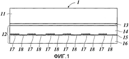
Фиг.1 - изображение в сечении соответствующего изобретению оптического защитного элемента.Figure 1 - image in cross section corresponding to the invention of an optical protective element.
Фиг.2 - схематичное изображение области поверхности оптического защитного элемента по фиг.1.Figure 2 is a schematic illustration of the surface area of the optical protective element of figure 1.
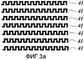
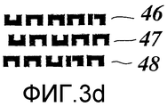
Фиг.3а-3d - схематичные изображения возможных образцов подструктурирования соответствующего изобретению оптического защитного элемента.3a-3d are schematic views of possible substructural patterns of an optical security element according to the invention.
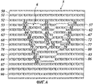
Фиг.4 - схематичное изображение области поверхности соответствующего изобретению оптического защитного элемента согласно другому варианту осуществления изобретения.4 is a schematic illustration of a surface region of an optical security element according to the invention according to another embodiment of the invention.
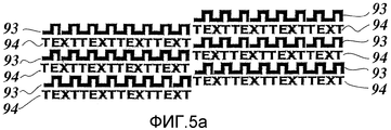
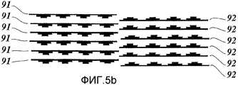
Фиг.5а и 5b - схематичное изображение фрагментов области поверхности соответствующего изобретению оптического защитного элемента согласно другому варианту осуществления изобретения.5a and 5b are schematic views of fragments of a surface region of an optical security element according to the invention according to another embodiment of the invention.
Фиг.6а и 6b - схематичное изображение фрагментов области поверхности соответствующего изобретению оптического защитного элемента согласно другому варианту осуществления изобретения.6a and 6b are schematic views of fragments of a surface region of an optical security element according to the invention according to another embodiment of the invention.
Фиг.7 - схематичное изображение нескольких частичных зон соответствующего изобретению оптического защитного элемента согласно другому варианту осуществления изобретения.Fig. 7 is a schematic illustration of several partial zones of an optical security element according to the invention in accordance with another embodiment of the invention.
На фиг.1 показана тисненная пленка 1, которая содержит несущую пленку 11 и переносимый слой 12, служащий в качестве оптического защитного элемента. Переносимый слой 12 содержит удаляемый и/или защитный слой 13 лака, слой 14 реплицирования, отражающий слой 15 и клеящий слой 16.Figure 1 shows an
Несущий слой 21 состоит, например, из полимерной пленки толщиной от 12 мкм до 50 мкм. На эту несущую пленку наносится удаляемый и/или защитный слой 13 лака толщиной от 0,3 до 1,2 мкм. На удаляемый и/или защитный слой лака наносится затем слой 14 реплицирования, предпочтительно, представляющий собой прозрачный, термопластичный пластик, который, например, посредством метода печати наносится по всей площади на пленочную структуру, образованную несущей пленкой 11 и удаляемым и/или защитным слоем 13 лака. Нанесение может осуществляться, например, валком глубокой печати с усилием нанесения 2,2 г/мм после сушки, причем сушка осуществляется в канале сушки при температуре от 100 до 120°. В слой реплицирования затем посредством инструмента для выполнения оттиска на участках 17 реплицируется микроскопическая поверхностная структура. Например, такая микроскопическая поверхностная структура выполняется оттиском при температуре примерно 130° с использованием никелевой матрицы.The
Однако также возможно, что реплицирование проводится способом ультрафиолетового реплицирования, при котором на пленочную структуру, образованную несущей пленкой 11 и удаляемым и/или защитным слоем 13 лака, наносится лак для ультрафиолетового реплицирования, который затем для реплицирования микроструктуры облучается на участках ультрафиолетовым излучением.However, it is also possible that replication is carried out by the ultraviolet replication method, in which a UV replication varnish is applied to the film structure formed by the
После реплицирования микроструктуры в слой реплицирования лак для реплицирования отверждается посредством образования полимерной сетки (сшивания) или иным способом.After the microstructure is replicated to the replication layer, the replication lacquer is cured by forming a polymer network (crosslinking) or otherwise.
Также можно формировать микроструктуру в слое 14 голографическими методами. Для этого, при голографической подсветке фоновая область накрывается соответствующей маской или микроструктура после подсветки в фоновой области удаляется. It is also possible to form the microstructure in
На слой 14 реплицирования затем наносится тонкий отражающий слой 15, который, предпочтительно, представляет собой тонкий напыляемый металлический слой или слой из материала с высоким коэффициентом отражения (HRI-слой). В качестве материала для HRI-слоя могут использоваться, например, TiO2, ZnS или Nb2O5. В качестве материала для металлического слоя могут, в основном, использоваться хром, алюминий, медь, железо, никель, серебро, золото или сплавы с этими металлами. Кроме того, вместо подобного металлического или диэлектрического отражающего слоя может использоваться тонкопленочная слоистая структура с несколькими диэлектрическими или с диэлектрическими и металлическими слоями.A thin
На образованную таким образом пленочную структуру затем наносится клеящий слой 16, который состоит, например, из термически активируемого клея.An
Для нанесения оптического защитного элемента на защищаемый документ или иной предмет, для которого должна быть обеспечена защита, тисненая пленка 1 с переносимым слоем 12 сначала наносится на защищаемый документ или иной защищаемый предмет, и затем под воздействием тепла запрессовывается в защищаемый документ или иной защищаемый предмет. При этом переносимый слой соединяется посредством клеящего слоя с соответствующей поверхностью защищаемого документа или иного защищаемого предмета. Затем, вследствие действия тепла, переносимый слой 12 отслаивается от несущей пленки 11, которая теперь отделяется от переносимого слоя 12 и удаляется. При этом на защищаемом документе или ином защищаемом предмете оказывается нанесенным соответствующий изобретению оптический защитный элемент, который состоит из переносимого слоя 12 или частей переносимого слоя 12.To apply an optical security element to a protected document or other object for which protection is to be provided, an
Также возможно, что соответствующий изобретению оптический защитный элемент является частью переводной или слоистой пленки, или образован из тисненой пленки, липкой пленки, переводной пленки или слоистой пленки. Кроме того, также возможно, что соответствующий изобретению оптический защитный элемент, наряду с показанными на фиг.1 слоями 13, 14, 15 и 16, также содержит другие слои. Подобные слои могут представлять собой, например, цветные декоративные слои или слои тонкопленочной многослойной системы, которая, посредством интерференции, формирует зависимые от угла наблюдения цветовые эффекты.It is also possible that the optical security element according to the invention is part of a transfer or laminate film, or is formed from an embossed film, an adhesive film, a transfer film or a laminate. In addition, it is also possible that the optical security element according to the invention, along with the
Кроме того, также можно отражающий слой 15 выполнить только частично или совсем отказаться от него, так что оптический защитный элемент действует как прозрачный, а не отражательный защитный элемент. Также можно отказаться от клеящего слоя 16.In addition, it is also possible to perform the
Как пояснено выше, микроструктура реплицируется в слой 14 реплицирования только на участках, так что в слое 14 реплицирования имеются участки 17, на которых микроструктура реплицирована, и участки 18, на которых микроструктура не реплицирована в поверхность слоя 14 реплицирования. На фиг.2 показан участок поверхности оптического защитного элемента, образованного переносимым слоем 12, с помощью которого наглядно показано, на каких участках осуществляется реплицирование микроструктуры в поверхность слоя 14 реплицирования.As explained above, the microstructure is replicated to the
На фиг.2 показан участок поверхности, который разделен на фоновую область 20 и множество участков 21-40 образца. Как показано на фиг.2, участки 21-39 образца имеют подструктурирование согласно функции подструктурирования, причем функция подструктурирования описывает подструктурирование соответствующего участка образца в форме меандрового образца. Участки 22, 24 и 26 образца удалены от участка 21 образца, предпочтительно на расстояние от 40 до 300 мкм. За счет такого расстояния достигается то, что, с одной стороны, оптические эффекты, сформированные микроструктурами, размещенными на участках 21, 22, 24 и 26 образца, смешиваются в глазу наблюдателя, а не разрешаются по отдельности, и, с другой стороны, обеспечиваются достаточно большие отдельные площадки для соответственно сформированной микроструктуры. Соответствующим образом разнесены относительно друг друга также участки 22, 24, 26, 27, 29, 31, 32, 34, 36, 37 и 39 образца.Figure 2 shows a surface area that is divided into a background region 20 and a plurality of sample sections 21-40. As shown in FIG. 2, the sample sections 21-39 have substructuring according to the substructuring function, wherein the substructuring function describes the substructuring of the corresponding sample portion in the form of a meander pattern. Sections 22, 24 and 26 of the sample are removed from the
Как показано на фиг.2, в V-образной частичной зоне 3 области 2 поверхности участки 23, 28, 35, 38, 40, 35, 30 и 24 образца размещены со сдвигом фазы относительно окружающих их участков 21, 22, 26, 27, 29, 31, 32, 34, 36, 37 и 39 образца.As shown in FIG. 2, in the V-shaped partial zone 3 of the
Участки 21-40 образца образуют в соответствии с этим, посредством вышеописанной функции подструктурирования, дополнительно структурированный линейный растр с множеством равномерно разнесенных дополнительно структурированных линий, причем линейный растр в частичной зоне 3 сдвинут по фазе для формирования скрытой информации.Sections 21-40 of the sample form, in accordance with this, by the above-described substructuring function, an additionally structured linear raster with a plurality of uniformly spaced further structured lines, the linear raster in the partial zone 3 being out of phase to generate hidden information.
На участках 21-40 образца сформирована первая микроструктура, представляющая собой, предпочтительно, дифракционную структуру двумерной (2D) или двумерной/трехмерной (2D/3D) голограммы. In sections 21-40 of the sample, a first microstructure is formed, which is preferably a diffraction structure of a two-dimensional (2D) or two-dimensional / three-dimensional (2D / 3D) hologram.
Кроме того, возможно, что микроструктура образована дифракционной решеткой с пространственной частотой более 300 линий/мм. Предпочтительные пространственные частоты подобной дифракционной решетки лежат в пределах от 600 до 1800 линий/мм. Кроме того, может быть предпочтительным использовать дифракционную решетку с очень высокой пространственной частотой, которая меньше длины волны света. Также могут применяться дифракционные решетки нулевого порядка или асимметричные дифракционные решетки. При этом параметры решетки для дифракционной решетки могут быть постоянными на участках 21-40 образца, но также могут изменяться, чтобы таким образом сформировать Kinegram®-эффект или иные оптические эффекты, которые формируют оптическое представление, зависимое от угла наблюдения.In addition, it is possible that the microstructure is formed by a diffraction grating with a spatial frequency of more than 300 lines / mm. Preferred spatial frequencies of such a diffraction grating are in the range of 600 to 1800 lines / mm. In addition, it may be preferable to use a diffraction grating with a very high spatial frequency, which is less than the wavelength of light. Zero-order diffraction gratings or asymmetric diffraction gratings can also be used. In this case, the grating parameters for the diffraction grating can be constant in
Кроме того, также возможно, что микроструктура выполнена в виде матовой структуры на участках 21-40 образца.In addition, it is also possible that the microstructure is made in the form of a matte structure in sections 21-40 of the sample.
Также возможно предусмотреть, посредством частичной металлизации, на участках 21-40 образца прозрачные зоны, и, напротив, в фоновой области 20 дифракционную структуру.It is also possible to provide, by means of partial metallization, in the areas 21-40 of the sample transparent zones, and, conversely, in the background region 20 a diffraction structure.
В фоновой области 20, которая составляется из не покрытых участками 21-40 образца частичных зон области 2 поверхности, не формируется микроструктура в слое 14 реплицирования, так что там имеет место планарная отражающая поверхность, от которой поднимается сформированная на участках 21-40 образца микроструктура.In the background region 20, which is composed of partial zones of the
Однако также возможно, что в фоновой области 20, вместо планарных отражающих элементов, сформирован пропускающий элемент, дифракционная решетка, формирующая голограмму дифракционная структура или матовая структура.However, it is also possible that in the background region 20, instead of planar reflective elements, a transmission element, a diffraction grating, a hologram forming a diffraction structure or a matte structure is formed.
Если на участках 21-39 образца сформирована дифракционная структура голограммы, то в фоновой области 20, предпочтительно, сформирована матовая структура, дифракционная решетка или дифракционная структура другой голограммы, которая отличается по направлению наблюдения и/или по цветовому представлению от первой голограммы. Если на участках 21-40 образца сформирована матовая структура, то в фоновой области 20, предпочтительно, сформирована вторая матовая структура с отличающейся характеристикой рассеяния. Если на участках 21-40 образца сформирована дифракционная решетка, то в фоновой области 20, предпочтительно, сформирована матовая структура или дифракционная решетка, отличающаяся от данной дифракционной решетки по параметрам решетки, например, по числу линий, или по ориентации.If a hologram diffraction structure is formed in sections 21-39 of the sample, then a matte structure, diffraction grating, or diffraction structure of another hologram that differs in the direction of observation and / or in color from the first hologram is formed in the background region 20. If a matte structure is formed in sections 21-40 of the sample, then a second matte structure with a different scattering characteristic is preferably formed in the background region 20. If a diffraction grating is formed in sections 21-40 of the sample, then an opaque structure or diffraction grating is formed in the background region 20, which differs from this diffraction grating in terms of grating parameters, for example, in the number of lines or in orientation.
Для верификации закодированной в области 2 поверхности информации (буква «V») применяется верифицирующий элемент, который состоит из линзового растра или выполненного печатью линейного растра с расстоянием между линиями, соответствующим расстоянию между линиями на участках 21-40 образца. Если верифицирующий элемент ориентируется на области 2 поверхности таким образом, что он покрывает участки 21, 22, 26, 27, 29, 31, 32, 34, 36, 37 и 39 образца, то обусловленный участками 21-40 образца оптический эффект формируется только в частичной зоне 3. Наблюдатель воспринимает в частичной зоне 3 оптический эффект, являющийся результатом суперпозиции оптического эффекта, формируемого в фоновой области 20, и оптического эффекта, формируемого на участках образца. Напротив, наблюдатель воспринимает в частичной зоне области 3 поверхности, окружающей частичную зону 3, только тот оптический эффект, который формируется в фоновой области 20. Если верифицирующий элемент ориентируется таким образом, что он покрывает участки 23, 25, 28, 30, 33, 35, 38 и 40 образца, то получается обратная ситуация. Если верифицирующий элемент не накладывается на область 2 поверхности, то для наблюдателя в этой области поверхности возникает оптическое представление, которое получается из суперпозиции оптического эффекта, сформированного в области образца, и оптического эффекта, сформированного в фоновой области. Если на участках образца и в фоновой области сформированы, например, дифракционные структуры двух различающихся по направлению наблюдения и/или цветовому представлению голограмм, то при наблюдении без верифицирующего элемента обе голограммы будут распознаваться наблюдателем, причем при использовании верифицирующего элемента одна голограмма наблюдается только в частичной зоне 3, или другая голограмма наблюдается только в частичной зоне области 2 поверхности, окружающей частичную зону 3.To verify the information surface encoded in region 2 (the letter “V”), a verification element is used, which consists of a lens raster or a linear raster printed with the distance between the lines corresponding to the distance between the lines in sections 21-40 of the sample. If the verification element is oriented on the
Так как усредненное заполнение поверхности функцией меандрового подструктурирования по отношению к разрешающей способности человеческого глаза постоянно, то она не влияет на формируемое при наблюдении восприятие в вышеописанных ситуациях. Однако она может распознаваться с помощью лупы или под микроскопом и служить в качестве дополнительного защитного признака или для идентификации. Как описано выше, при сдвиге верифицирующего элемента в области 2 поверхности за счет подструктурирования возникают дополнительные оптически распознаваемые эффекты, которые могут служить в качестве дополнительного защитного признака.Since the averaged filling of the surface with the meander substructuring function with respect to the resolution of the human eye is constant, it does not affect the perception formed during observation in the above situations. However, it can be recognized with a magnifying glass or under a microscope and serve as an additional security feature or for identification. As described above, when the verification element is shifted in the
Сдвиг фазы на 180° между участками образца в частичной зоне 3 и окружающими их участками образца обеспечивает особенно большой контраст при наблюдении через верифицирующий элемент, так как тогда может быть покрыта вся область поверхности участков образца в частичной зоне 3, а окружающие их участки образца не покрыты. Разумеется, при этом также возможно некоторое отклонение от фазового сдвига на 180°. Также может обеспечить преимущества, если на том или ином участке образца предусмотреть фазовый сдвиг, существенно отличающийся от 180°, например, на 45° или 135°. Так, например, можно реализовать скрытые изображения с градациями серого, в которых градации серой шкалы кодированы посредством фазового сдвига.A 180 ° phase shift between the sections of the sample in partial zone 3 and the surrounding sections of the sample provides a particularly large contrast when observed through a verification element, since then the entire surface area of the sections of the sample in partial zone 3 can be covered, and the surrounding sections of the sample are not covered . Of course, in this case, some deviation from the phase shift by 180 ° is also possible. It can also provide advantages if a phase shift is provided for in a particular section of the sample that differs significantly from 180 °, for example, by 45 ° or 135 °. So, for example, you can implement latent images with grayscale, in which the gradation of the gray scale is encoded by phase shift.
Вместо применения линейного растра линейной формы для конфигурации участков 21-40 образца можно применять комплексный, например, волнообразный линейный растр, причем в данном случае также в частичных зонах линейного растра можно осуществить фазовый сдвиг участков образца, чтобы кодировать скрытую информацию в линейном растре. Для оценки используется верифицирующий элемент, который покрывает участки поверхности в соответствии с этим линейным растром. Instead of using a linear raster of linear shape for the configuration of sections 21-40 of the sample, you can use a complex, for example, a wave-like linear raster, and in this case, also in partial zones of the linear raster, you can phase shift sections of the sample to encode hidden information in a linear raster. For evaluation, a verification element is used that covers surface areas in accordance with this linear raster.
Со ссылками на фиг.3а-4 ниже поясняются другие возможности подструктурирования участков образца. With reference to FIGS. 3a-4 below, other possibilities of substructuring portions of the sample are explained.
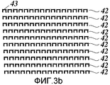
На фиг.3а показано множество участков 41 образца, которые дополнительно структурированы согласно функции подструктурирования, описывающей меандровое подструктурирование. При этом не требуется, чтобы функция подструктурирования описывала образец взаимосвязанного подструктурирования. Так на фиг. 3b показаны дополнительно структурированные участки 42 образца, которые дополнительно структурированы согласно образцу подструктурирования, сформированному из множества подобных элементов 43.Figure 3a shows a plurality of
Расстояния между отдельными элементами и ориентация отдельных элементов могут при этом варьироваться, если средняя разрешаемая человеческим глазом степень заполнения поверхности образца подструктурирования остается постоянной.The distances between the individual elements and the orientation of the individual elements may vary if the average degree of filling of the surface of the substructuring sample allowed by the human eye remains constant.
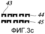
На фиг.3с показано такое подструктурирование двух смежных участков 44 и 45 образца, в которых расстояние между отдельными элементами 43 варьируется. Как показано на фиг.3с, при этом среднее заполнение поверхности образца подструктурирования остается постоянным. За счет подобного изменения расстояний можно в оптическом защитном элементе кодировать дополнительную, например, оцениваемую электронным способом информацию. On figs shows such a substructuring of two
Фиг.3d иллюстрирует возможность кодирования информации в подструктурировании не только за счет различного расстояния между отдельными элементами, но и за счет их различной ориентации, и при этом сохранения среднего разрешаемого человеческим глазом заполнения поверхности образца подструктурирования постоянным.3D illustrates the ability to encode information in substructuring not only due to the different distances between the individual elements, but also due to their different orientations, while keeping the average resolution of the human surface filling of the surface of the substructuring sample constant.
Фиг.3d показывает такие три смежные участка 46, 47, 48 образца, которые, соответственно, образованы пятью отдельными элементами, которые различаются по своей ориентации и по своему расстоянию.Fig. 3d shows such three
Кроме того, можно кодировать информацию дополнительно посредством различного фазового положения смежных отдельных элементов в образце подструктурирования.In addition, it is possible to further encode information by means of the different phase position of adjacent individual elements in the substructuring pattern.
На фиг.4 показана область 5 поверхности, которая разделена на фоновую область 50 и участки 51-90 образца. Участки 50-90 образца при этом структурированы согласно функции подструктурирования, которая описывает микротекст или нанотекст. Высота букв этого микротекста или нанотекста составляет в данном примере выполнения, показанном на фиг.4, 60 мкм.Figure 4 shows a
Участки поверхности в V-образной частичной зоне 6 области 5 поверхности, аналогично примеру выполнения по фиг.2, сдвинуты по фазе относительно окружающих их участков образца. Образующая фоновую область 50 часть оптического защитного элемента выполнена как фоновая область 2, согласно фиг.1 и фиг.2, и имеет, например, отражающую планарную поверхность, дифракционную решетку, дифракционную структуру голограммы или матовую структуру. Покрытые подструктурированными участками 51-90 образца зоны оптического защитного элемента выполнены как участки 21-40 образца по фиг.2 и фиг.1 и имеют, например, отражающую планарную поверхность, дифракционную решетку, дифракционную структуру голограммы или матовую структуру.The surface areas in the V-shaped
Вместо показанной на фиг.4, примененной для подструктурирования комбинации букв “TEXT”, разумеется, можно выбрать иную комбинацию букв, которая также может отображать сложное содержание. Кроме того, можно вместо или в комбинации с буквами или комбинациями букв для подструктурирования применять наноизображения.Instead of the combination of letters “TEXT” shown in FIG. 4, used, of course, you can choose a different combination of letters, which can also display complex content. In addition, instead of or in combination with letters or letter combinations, nanoimages can be used for substructuring.
Кроме того, также возможно, что подструктурирование может составляться из комбинации различных вышеописанных возможных вариантов подструктурирования, или, например, построчно может применяться одно или другое подструктурирование.In addition, it is also possible that the substructuring can be composed of a combination of the various possible substructuring options described above, or, for example, one or the other substructuring can be applied line by line.
На фиг.5а показано подструктурирование участков образца и фоновой области, при котором фоновая область дополнительно структурирована посредством подструктурирования 94, и участки образца - посредством подструктурирования 93. Fig. 5a shows the substructuring of sample sections and the background region, in which the background region is further structured by
При этом в областях подструктурирований 93 и 94 могут предусматриваться различные дифракционные оптические структуры. Линейный растр вновь сдвигается на полпериода в соответствии с кодируемой скрытой информацией. Если накладывается верифицирующий элемент (например, линейный растр из прозрачных и непрозрачных участков с одинаковым периодом), то он накрывает, например, на левой стороне, структуры в подструктурировании 94, в то время как верифицирующий элемент на правой стороне накрывает соответственно структуры в подструктурировании 93.Moreover, in the areas of
По сравнению с вышеописанными вариантами, в данном случае речь идет о дополнительно структурированной, согласно “TEXT”, фоновой области меандра.Compared to the options described above, in this case we are talking about an additionally structured, according to “TEXT”, background area of the meander.
В фоновой области двух различным образом дополнительно структурированных линейных растров могут, кроме того, находиться, например, зеркальная или другая структура, которая отличается от обеих дифракционных оптических структур линейного растра, например, в меандровой или текстовой.In the background region of two differently additionally structured linear rasters, there can also be, for example, a mirror or other structure that differs from both diffraction optical structures of a linear raster, for example, in a meander or text.
На фиг.5b иллюстрируется другая возможность дополнительного структурирования участков образца.Fig. 5b illustrates another possibility of further structuring of sample portions.
На фиг.5b показано множество дополнительно структурированных участков 91 образца, которые сдвинуты по фазе относительно дополнительно структурированных участков 92 образца. Как показано на фиг.5, участки 91 и 92 образца дополнительно структурированы посредством соответствующего асимметричного образца подструктурирования, так что центр тяжести поверхности участков образца за счет такого дополнительного структурирования смещается вверх или вниз. 5b shows a plurality of additionally structured
Этот эффект может быть применен для того, чтобы, вместо показанного на фиг.2 и фиг.4 сдвига фазы в частичных зонах 3 или 6, соответственно, сдвинуть только центр тяжести поверхности дополнительно структурированного участка образца, полученного за счет подструктурирования, на половину периода верифицирующего элемента. Как показано на фиг.5b, такой фазовый сдвиг на половину периода может быть заменен зеркальным отображением.This effect can be applied in order to, instead of the phase shift shown in Fig. 2 and Fig. 4 in
Разумеется, также можно, вместо показанного на фиг.5b зеркально-симметричного образца подструктурирования, для участков 91 и 92 образца применить любые различные образцы подструктурирования, которые различаются по своему центру тяжести. Однако при этом предпочтительным является то, что средняя степень заполнения этого образца подструктурирования по отношению к разрешающей способности человеческого глаза остается постоянной и согласованной, так что скрытая информация не может быть распознана невооруженным глазом.Of course, it is also possible, instead of the mirror-symmetric substructuring pattern shown in FIG. 5b, to apply any different substructuring patterns for
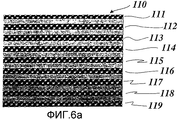
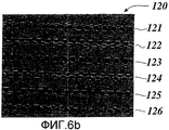
На фиг.6а и 6b показаны дальнейшие возможности подструктурирования участков образца посредством наложения двумерного растра. Figures 6a and 6b show further possibilities for substructuring portions of a sample by superimposing a two-dimensional raster.
Так на фиг.6а показана область 110 поверхности с множеством участков 111-119 образца, а на фиг.6b показана область 120 поверхности с множеством участков 121-126 образца. Как показано на этих чертежах, подструктурирование участков образца получается при этом, соответственно, посредством наложения точечного или линейного растра. Можно видеть, что соответствующие смежные участки образца могут иметь различающийся образец, который возникает вследствие этого наложения. В сечении, однако, каждый участок образца имеет одну и ту же оптическую плотность, так что соответственно покрытая дифракционно-оптическими структурами поверхность представляется наблюдателю однородной, так как это подструктурирование не разрешается глазом. 6a, a
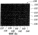
На фиг.6с показана область 130 поверхности с участками 131-136 и 137-144 образца, которые конфигурированы согласно двумерному растру. Показанный на фиг.6а и 6b принцип подструктурирования посредством наложения линейного и точечного растра применяется в данном случае для того, чтобы кодировать на участке образца две различные скрытые информации, которые могут оцениваться при двух различных направлениях ориентации (0° и 90°).Fig. 6c shows a
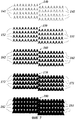
На фиг.7 показано множество частичных зон 140, 150, 160, 170 и 180 области поверхности. В частичной зоне 140 размещено множество сдвинутых по фазе относительно друг друга подструктурированных участков 142 и 141 образца. В частичных зонах 150, 160, 170 и 180 размещено множество сдвинутых по фазе относительно друг друга подструктурированных участков 152 и 151, 162 и 161, 172 и 171, 182 и 181 образца.7, a plurality of
Как видно из фиг.7, образцы подструктурирования в частичных зонах 140, 150, 160, 170 и 180 различаются тем, что их усредненная, разрешаемая человеческим глазом степень заполнения поверхности различна. Таким образом, усредненная степень заполнения поверхности образца подструктурирования постоянна только в соответствующей частичной зоне, так что кодированная за счет сдвига фазы информация для наблюдателя остается неразличимой без использования верифицирующего элемента.As can be seen from Fig. 7, substructuring patterns in the
За счет подобного парциально различающегося подструктурирования участков образца достигается то, что соотношение усредненной степени заполнения поверхности участками образца и фоновой областью парциально варьируется, так что на передний план выступает отдельно либо больше оптических эффектов, формируемых на участках образца, либо больше оптических эффектов, формируемых в фоновой области. При этом скрытая информация может распознаваться посредством верифицирующего элемента с более высоким контрастом при среднем отношении площадей участков образца и фоновой области. Контраст исчезает при 0% или 100% заполнении поверхности участками образца.Due to this partial differing substructuring of the sample sections, it is achieved that the ratio of the average degree of surface filling with the sample sections and the background region is partially varied, so that either more optical effects formed in the sample sections or more optical effects formed in the background stand out separately area. In this case, hidden information can be recognized by means of a verification element with higher contrast with an average ratio of the areas of the sample areas and the background area. The contrast disappears when 0% or 100% of the surface is filled with portions of the sample.
За счет такого парциального варьирования функции подструктурирования, которое также может осуществляться «квази-непрерывно», может, таким образом, формироваться дополнительный распознаваемый наблюдателем защитный признак, например, информация изображения на представлении в градациях серого.Due to such partial variation of the substructuring function, which can also be carried out “quasi-continuously”, an additional security feature recognized by the observer can be formed in this way, for example, image information in a presentation in grayscale.
Claims (21)
отличающийся тем, что
первая микроструктура (17) представляет собой дифракционную структуру, в частности дифракционную решетку, дифракционную структуру для формирования голограммы или матовую структуру, область (2,5) поверхности разделена на микроскопически мелкие участки (21-40, 51-90) образца и фоновую область (20, 50), и первая микроструктура (17) сформирована на участках (21-39, 51-90) образца, но не в фоновой области, микроскопически мелкие участки (21-39, 51-90) образца размещены в области (2, 5) поверхности в форме муарового образца, в котором закодирована оцениваемая посредством соответствующего верифицирующего элемента скрытая информация в виде защитного признака, причем муаровый образец имеет, по меньшей мере, один линейный растр с множеством линий с расстоянием между линиями в диапазоне от 40 до 200 мкм, причем линейный растр на участках сдвинут по фазе для формирования скрытой информации, и микроскопически мелкие участки (21-39, 51-90) образца дополнительно структурированы в соответствии с функцией под-структурирования, которая описывает служащее в качестве дополнительного защитного признака микроскопическое под-структурирование муарового образца, которое кодирует дополнительную информацию в области поверхности, при этом дополнительная информация не имеет возможности считывания ни невооруженным глазом, ни посредством верифицирующего элемента.1. An optical security element with a substrate layer (14), and in the regions (2, 5) of the surface of the substrate layer, a first microstructure (17) is formed in regions to form a first optically recognizable effect in the substrate layer (14),
characterized in that
the first microstructure (17) is a diffraction structure, in particular a diffraction grating, a diffraction structure for forming a hologram or a matte structure, the surface region (2.5) is divided into microscopically small sections (21-40, 51-90) of the sample and the background region ( 20, 50), and the first microstructure (17) is formed in the areas (21-39, 51-90) of the sample, but not in the background region, microscopically small sections (21-39, 51-90) of the sample are located in the region (2, 5) surfaces in the form of a moire pattern in which the evaluated medium is encoded of the corresponding verification element, hidden information in the form of a security feature, wherein the moire pattern has at least one linear raster with many lines with a distance between the lines in the range of 40 to 200 μm, the linear raster in the sections shifted in phase to generate hidden information, and microscopically small sections (21-39, 51-90) of the sample are additionally structured in accordance with the sub-structuring function, which describes the microscopic function as an additional protective feature d-structuring moiré sample which encodes the additional information in the surface region, wherein the additional information is not able to read either the naked eye or by a verifying element.
Applications Claiming Priority (2)
| Application Number | Priority Date | Filing Date | Title |
|---|---|---|---|
| DE10328760A DE10328760B4 (en) | 2003-06-25 | 2003-06-25 | Optical security element |
| DE10328760.4 | 2003-06-25 |
Publications (2)
| Publication Number | Publication Date |
|---|---|
| RU2006101979A RU2006101979A (en) | 2006-08-10 |
| RU2358317C2 true RU2358317C2 (en) | 2009-06-10 |
Family
ID=33521025
Family Applications (1)
| Application Number | Title | Priority Date | Filing Date |
|---|---|---|---|
| RU2006101979/09A RU2358317C2 (en) | 2003-06-25 | 2004-06-16 | Optical protective element |
Country Status (12)
| Country | Link |
|---|---|
| US (1) | US7265904B2 (en) |
| EP (1) | EP1636737B1 (en) |
| JP (1) | JP4601008B2 (en) |
| KR (1) | KR101127135B1 (en) |
| CN (1) | CN100437637C (en) |
| AU (1) | AU2004249865B2 (en) |
| BR (1) | BRPI0411907B1 (en) |
| CA (1) | CA2528352C (en) |
| DE (1) | DE10328760B4 (en) |
| RU (1) | RU2358317C2 (en) |
| TW (1) | TWI333182B (en) |
| WO (1) | WO2004113954A2 (en) |
Cited By (1)
| Publication number | Priority date | Publication date | Assignee | Title |
|---|---|---|---|---|
| RU2605996C2 (en) * | 2011-03-31 | 2017-01-10 | Тинк Лаборатори Ко., Лтд. | Information display system and dot pattern printed material |
Families Citing this family (42)
| Publication number | Priority date | Publication date | Assignee | Title |
|---|---|---|---|---|
| US7336422B2 (en) | 2000-02-22 | 2008-02-26 | 3M Innovative Properties Company | Sheeting with composite image that floats |
| US7616332B2 (en) | 2004-12-02 | 2009-11-10 | 3M Innovative Properties Company | System for reading and authenticating a composite image in a sheeting |
| DE102005006277B4 (en) * | 2005-02-10 | 2007-09-20 | Ovd Kinegram Ag | Method for producing a multilayer body |
| DE102005006231B4 (en) * | 2005-02-10 | 2007-09-20 | Ovd Kinegram Ag | Method for producing a multilayer body |
| GB2429187B (en) * | 2005-08-15 | 2007-08-08 | Rue De Int Ltd | Security devices for security substrates |
| DE102005049891A1 (en) | 2005-10-17 | 2007-04-19 | Leonhard Kurz Gmbh & Co. Kg | Metallized multilayer body |
| DE102006016139A1 (en) * | 2006-04-06 | 2007-10-18 | Ovd Kinegram Ag | Multi-layer body with volume hologram |
| DE102006037431A1 (en) * | 2006-08-09 | 2008-04-17 | Ovd Kinegram Ag | Production of multi-layer bodies useful in element for security- and value document such as banknotes and credit cards, by forming a relief structure in an area of replication layer and applying a layer on carrier and/or replication layer |
| US7800825B2 (en) | 2006-12-04 | 2010-09-21 | 3M Innovative Properties Company | User interface including composite images that float |
| US8493510B2 (en) * | 2006-12-12 | 2013-07-23 | Time Warner Inc. | Method and apparatus for concealing portions of a video screen |
| JP2008268451A (en) * | 2007-04-18 | 2008-11-06 | Sanyo Electric Co Ltd | Optical element, master standard, resin master, resin mold, and metal mold |
| US7851110B2 (en) * | 2007-04-20 | 2010-12-14 | Photronics, Inc. | Secure photomask with blocking aperture |
| US7790340B2 (en) * | 2007-04-20 | 2010-09-07 | Photronics, Inc. | Photomask with detector for optimizing an integrated circuit production process and method of manufacturing an integrated circuit using the same |
| US7943273B2 (en) * | 2007-04-20 | 2011-05-17 | Photronics, Inc. | Photomask with detector for optimizing an integrated circuit production process and method of manufacturing an integrated circuit using the same |
| CN102830494B (en) | 2007-07-11 | 2015-04-01 | 3M创新有限公司 | Sheeting with composite image that floats |
| CN101878438B (en) | 2007-11-27 | 2013-09-25 | 3M创新有限公司 | Methods for forming sheeting with a composite image that floats and a master tooling |
| DE102008036480A1 (en) * | 2008-08-05 | 2010-02-11 | Giesecke & Devrient Gmbh | Method for producing security elements with adapted motif layers |
| JP5589268B2 (en) * | 2008-08-29 | 2014-09-17 | 大日本印刷株式会社 | Relief type diffraction grating or hologram |
| US7995278B2 (en) | 2008-10-23 | 2011-08-09 | 3M Innovative Properties Company | Methods of forming sheeting with composite images that float and sheeting with composite images that float |
| US8111463B2 (en) | 2008-10-23 | 2012-02-07 | 3M Innovative Properties Company | Methods of forming sheeting with composite images that float and sheeting with composite images that float |
| GB0821872D0 (en) * | 2008-12-01 | 2009-01-07 | Optaglio Sro | Optical device offering multiple pattern switch and/or colour effect and method of manufacture |
| KR101025822B1 (en) * | 2009-06-11 | 2011-03-30 | 한국조폐공사 | Apparatus for security code recognition of electromagnetic band gap pattern |
| WO2011094221A2 (en) | 2010-01-26 | 2011-08-04 | Nanoink, Inc. | Moire patterns generated by angular illumination of surfaces |
| KR100980442B1 (en) * | 2010-03-12 | 2010-09-07 | 한국조폐공사 | Device for counterfeit check and article including the device |
| DE102010050031A1 (en) * | 2010-11-02 | 2012-05-03 | Ovd Kinegram Ag | Security element and method for producing a security element |
| FR2974930B1 (en) * | 2011-05-03 | 2013-11-08 | Media Relief | METHOD FOR MANUFACTURING AN IRIDESCENT IMAGE, IMAGE OBTAINED AND DEVICE COMPRISING IT, PROGRAM THEREFOR |
| RU2467879C1 (en) * | 2011-06-30 | 2012-11-27 | Федеральное Государственное Унитарное Предприятие "Гознак" (Фгуп "Гознак") | Valuable document with optically variable structure (versions) |
| JP2014526711A (en) * | 2012-06-12 | 2014-10-06 | メディア レリーフ | Method for creating an iridescent image, the resulting image, a device with the iridescent image, and an associated program |
| CH710402A2 (en) * | 2014-11-24 | 2016-05-31 | Paper Dna Ag | Paper authentication device. |
| DE102015100280A1 (en) * | 2015-01-09 | 2016-07-14 | Ovd Kinegram Ag | Method for the production of security elements and security elements |
| WO2016208590A1 (en) * | 2015-06-22 | 2016-12-29 | 凸版印刷株式会社 | Medium for forming hologram image, and image display medium using same |
| FR3046111B1 (en) * | 2015-12-29 | 2022-03-25 | Arjowiggins Security | SECURE ARTICLE COMPRISING A REVELATION FRAME AND A COMBINED IMAGE |
| US9830489B2 (en) * | 2016-03-29 | 2017-11-28 | Analog Devices, Inc. | Simple code reader |
| WO2017206724A1 (en) | 2016-05-31 | 2017-12-07 | 昇印光电(昆山)股份有限公司 | Decorative member, cover plate for electronic apparatus, and electronic apparatus |
| DE102016113513A1 (en) * | 2016-07-21 | 2018-01-25 | Fibro Gmbh | Device and method for generating and detecting a forgery-proof identification |
| NL2018613B1 (en) * | 2017-03-30 | 2018-10-10 | Orbid Ltd | Two-dimensional marker for marking an object, method and system for generating the marker, method and system for generating a marker code, and method and system for authenticating an object |
| DE102017003281A1 (en) | 2017-04-04 | 2018-10-04 | Giesecke+Devrient Currency Technology Gmbh | Security element with relief structure and manufacturing method therefor |
| GB2565561A (en) * | 2017-08-15 | 2019-02-20 | Security Print Solutions Ltd | Document security |
| US10429743B2 (en) | 2017-11-30 | 2019-10-01 | International Business Machines Corporation | Optical mask validation |
| US10650111B2 (en) | 2017-11-30 | 2020-05-12 | International Business Machines Corporation | Electrical mask validation |
| WO2019116385A1 (en) * | 2017-12-13 | 2019-06-20 | Jain, Dinesh Kumar | System and method for generating and verifying holographic tags |
| CN108983433A (en) * | 2018-09-25 | 2018-12-11 | 上海宏盾防伪材料有限公司 | A kind of diffraction optics safety device with alternating binary coding hiding information |
Family Cites Families (14)
| Publication number | Priority date | Publication date | Assignee | Title |
|---|---|---|---|---|
| US5178418A (en) * | 1991-06-25 | 1993-01-12 | Canadian Bank Note Co., Ltd. | Latent images comprising phase shifted micro printing |
| US5379131A (en) * | 1991-12-11 | 1995-01-03 | Dai Nippon Printing Co., Ltd. | Method of preventing forgery of diffraction grating pattern and forgery-proof diffraction grating pattern recording structure |
| DE59500254D1 (en) * | 1995-03-16 | 1997-06-26 | Landis & Gyr Tech Innovat | Optical information carrier |
| TW409230B (en) | 1998-01-16 | 2000-10-21 | Ind Tech Res Inst | Hologram false-preventing recognition structure and the method thereof |
| US6351537B1 (en) | 1998-10-05 | 2002-02-26 | 3M Innovative Properties Company | Verifiable holographic article |
| JP2001144944A (en) * | 1999-11-16 | 2001-05-25 | Hitachi Ltd | Printed matter and print system |
| WO2001053113A1 (en) * | 2000-01-21 | 2001-07-26 | Flex Products, Inc. | Optically variable security devices |
| GB0015871D0 (en) * | 2000-06-28 | 2000-08-23 | Rue De Int Ltd | A security device |
| DE10044465A1 (en) * | 2000-09-08 | 2002-03-21 | Giesecke & Devrient Gmbh | Data carrier with an optically variable element |
| JP2002372610A (en) * | 2001-06-13 | 2002-12-26 | Dainippon Printing Co Ltd | Diffraction grating which can be identified for authenticity and recording medium provided with the same |
| GB0117391D0 (en) * | 2001-07-17 | 2001-09-05 | Optaglio Ltd | Optical device and method of manufacture |
| JP4228563B2 (en) * | 2001-09-05 | 2009-02-25 | 凸版印刷株式会社 | Image forming body |
| GB0202646D0 (en) * | 2002-02-05 | 2002-03-20 | Optaglio Ltd | Secure hidden data protection optically variable label |
| JP4270438B2 (en) * | 2002-07-02 | 2009-06-03 | 大日本印刷株式会社 | Display body containing hidden pattern by light diffraction structure |
-
2003
- 2003-06-25 DE DE10328760A patent/DE10328760B4/en not_active Expired - Fee Related
-
2004
- 2004-06-11 TW TW093116805A patent/TWI333182B/en not_active IP Right Cessation
- 2004-06-16 AU AU2004249865A patent/AU2004249865B2/en not_active Ceased
- 2004-06-16 US US10/562,331 patent/US7265904B2/en not_active Expired - Fee Related
- 2004-06-16 CA CA2528352A patent/CA2528352C/en not_active Expired - Fee Related
- 2004-06-16 WO PCT/EP2004/006467 patent/WO2004113954A2/en active Search and Examination
- 2004-06-16 EP EP04739935A patent/EP1636737B1/en not_active Not-in-force
- 2004-06-16 JP JP2006515946A patent/JP4601008B2/en not_active Expired - Fee Related
- 2004-06-16 CN CNB2004800179887A patent/CN100437637C/en not_active Expired - Fee Related
- 2004-06-16 BR BRPI0411907A patent/BRPI0411907B1/en not_active IP Right Cessation
- 2004-06-16 RU RU2006101979/09A patent/RU2358317C2/en not_active IP Right Cessation
- 2004-06-16 KR KR1020057024333A patent/KR101127135B1/en not_active IP Right Cessation
Cited By (1)
| Publication number | Priority date | Publication date | Assignee | Title |
|---|---|---|---|---|
| RU2605996C2 (en) * | 2011-03-31 | 2017-01-10 | Тинк Лаборатори Ко., Лтд. | Information display system and dot pattern printed material |
Also Published As
| Publication number | Publication date |
|---|---|
| DE10328760B4 (en) | 2007-05-24 |
| US20060209412A1 (en) | 2006-09-21 |
| KR101127135B1 (en) | 2012-03-20 |
| US7265904B2 (en) | 2007-09-04 |
| KR20060030046A (en) | 2006-04-07 |
| CA2528352C (en) | 2012-02-21 |
| EP1636737B1 (en) | 2013-02-20 |
| JP2007507021A (en) | 2007-03-22 |
| RU2006101979A (en) | 2006-08-10 |
| AU2004249865A1 (en) | 2004-12-29 |
| CA2528352A1 (en) | 2004-12-29 |
| CN100437637C (en) | 2008-11-26 |
| BRPI0411907B1 (en) | 2016-11-22 |
| BRPI0411907A (en) | 2006-08-08 |
| TW200509006A (en) | 2005-03-01 |
| CN1813262A (en) | 2006-08-02 |
| JP4601008B2 (en) | 2010-12-22 |
| AU2004249865B2 (en) | 2009-07-02 |
| EP1636737A2 (en) | 2006-03-22 |
| TWI333182B (en) | 2010-11-11 |
| DE10328760A1 (en) | 2005-01-20 |
| WO2004113954A2 (en) | 2004-12-29 |
| WO2004113954A3 (en) | 2005-04-21 |
Similar Documents
| Publication | Publication Date | Title |
|---|---|---|
| RU2358317C2 (en) | Optical protective element | |
| RU2448840C2 (en) | Covered instrument | |
| RU2435675C2 (en) | Multilayer substrate with microoptical facility | |
| RU2344480C2 (en) | Optical protective element and system for visualisation of hidden information | |
| RU2573346C2 (en) | Security element, valuable document with such security element, and also method of manufacturing security element | |
| RU2255000C1 (en) | Protective element | |
| EP1782108B1 (en) | A method of creating a three-dimensional image, a diffractive element and method of creating the same | |
| RU2596088C2 (en) | Protective element for counterfeit-proof documents, valuable documents or similar | |
| US20130069360A1 (en) | Security document with integrated security device and method of manufacture | |
| CA2723474C (en) | Optical security element | |
| JPH09134111A (en) | Information recording medium | |
| JP2009168928A (en) | Display material and article with display material | |
| EA017394B1 (en) | Microoptical system for forming visual images | |
| CN107848321A (en) | Optical devices with optical array | |
| US11529823B2 (en) | Security device and method of manufacture thereof | |
| EP3332276B1 (en) | Azimuthally modulated scattering device | |
| US20140103634A1 (en) | Structured color filter device | |
| RU2725793C1 (en) | Method of producing a multilayer polymer protected article with an identifying optically variable image with instrument-determined features and a multilayer article with an identifying optically variable image | |
| AU2015100643A4 (en) | Shaped microlenses | |
| RU2271413C2 (en) | Surface element with volumetric microstructure possessing angular anisotropy of color an transparence, method for production of element |
Legal Events
| Date | Code | Title | Description |
|---|---|---|---|
| MM4A | The patent is invalid due to non-payment of fees |
Effective date: 20170617 |