RU2355652C2 - Method of producing high-precision cylindrical micro-lenses with various section profiles - Google Patents
Method of producing high-precision cylindrical micro-lenses with various section profiles Download PDFInfo
- Publication number
- RU2355652C2 RU2355652C2 RU2007127648/03A RU2007127648A RU2355652C2 RU 2355652 C2 RU2355652 C2 RU 2355652C2 RU 2007127648/03 A RU2007127648/03 A RU 2007127648/03A RU 2007127648 A RU2007127648 A RU 2007127648A RU 2355652 C2 RU2355652 C2 RU 2355652C2
- Authority
- RU
- Russia
- Prior art keywords
- preform
- lenses
- aspherical
- microlenses
- glass
- Prior art date
Links
Images


Abstract
Description
Изобретение относится к оптической и электронной промышленностям, к лазерной технике, в частности к технологии изготовления цилиндрических микролинз (ЦМЛ), в том числе с асферической поверхностью (АЦМЛ), обладающих высокой эффективностью фокусирования излучения и высокой степенью исправления хроматических аберраций, которые могут быть использованы при конструировании систем для построения и передачи изображения и световой энергии и для обработки информации.The invention relates to the optical and electronic industries, to laser technology, in particular to the technology of manufacturing cylindrical microlenses (DML), including with an aspherical surface (ATSML), which have a high focusing efficiency of radiation and a high degree of correction of chromatic aberrations that can be used when designing systems for constructing and transmitting images and light energy and for processing information.
Микролинзами (МЛ) называем здесь любые линзы малого размера, диаметром 2-5 мм и менее. Цилиндрической линзой называют стержни, ограниченные двумя цилиндрическими поверхностями или одной цилиндрической поверхностью и плоскостью. Эти линзы, как и сферические, бывают положительными и отрицательными и могут иметь различную форму.Microlenses (ML) are here any lenses of small size, with a diameter of 2-5 mm or less. A cylindrical lens is a rod defined by two cylindrical surfaces or one cylindrical surface and a plane. These lenses, like spherical ones, are positive and negative and can have various shapes.
В цилиндрической линзе различают два основных сечения: меридиональное - М, проходящее через ось цилиндрической поверхности OO1 перпендикулярно плоской поверхности линзы, и сагиттальное - С, расположенное перпендикулярно оси цилиндрической поверхности.Two main sections are distinguished in a cylindrical lens: meridional — M, passing through the axis of the cylindrical surface OO1 perpendicular to the flat surface of the lens, and sagittal — C, located perpendicular to the axis of the cylindrical surface.
В настоящее время в современных оптоэлектронных, коммуникационных и лазерных системах медицинского и специального назначения необходимо передавать, концентрировать и вводить излучения различных длин волн от УФ до ИК диапазона в очень узких пучках - микронного и субмикронного диаметра. Для этих целей широко применяются миниатюрные линзы - микролинзы.Currently, in modern optoelectronic, communication and laser systems for medical and special purposes, it is necessary to transmit, concentrate and introduce radiation of various wavelengths from the UV to the IR range in very narrow beams - micron and submicron diameters. For these purposes, miniature lenses are widely used - microlenses.
Совершенствование параметров МЛ - расширение диапазона прозрачности, увеличение светосилы, а также совершенствование технологии их изготовления - является актуальной задачей современной оптики и оптоэлектроники. Главным направлением совершенствования технологии изготовления МЛ и повышения их оптических параметров является замена классических МЛ, которые представляют собой обычные сферические линзы, только меньшего диаметра, цилиндрическими микролинзами (ЦМЛ) и цилиндрическими микролинзами с асферической поверхностью (АЦМЛ). Потребность в ЦМЛ и АЦМЛ очень велика, так как возрастает число областей их применения, а также растут масштабы производства приборов различного назначения, в которых применяются ЦМЛ и АЦМЛ.Improving the parameters of ML - expanding the transparency range, increasing the aperture ratio, as well as improving the technology of their manufacture - is an urgent task of modern optics and optoelectronics. The main direction of improving the manufacturing technology of MLs and increasing their optical parameters is the replacement of classical MLs, which are ordinary spherical lenses, only of smaller diameter, with cylindrical microlenses (TsML) and cylindrical microlenses with an aspherical surface (ATSML). The need for DTMs and ATSML is very great, as the number of areas of their application is increasing, and the scale of production of devices for various purposes that use DTMs and ATSML is growing.
В настоящее время известны способы изготовления линз, где формирование сферической поверхности производится традиционными методами - механической обработкой стекла в индивидуальном порядке, причем каждая линза или небольшая группа линз обрабатывается отдельно на специальном оборудовании. Заготовки линз получают на стекловаренных заводах в виде прессовок, имеющих форму готовых деталей, но с припусками на обработку. Обработка заготовок линз включает основные этапы: грубое шлифование алмазным инструментом, тонкое шлифование, например, с подачей абразивного микропорошка с водой, полирование с подачей полирующей суспензии, промывку в растворителях, протирку, центрирование, просветление с помощью просветляющих покрытий химическим способом или испарением в вакууме (см. А.В.Сулим. Производство оптических деталей. М.: Высшая школа, 1975 г., с.9-11).Currently known methods of manufacturing lenses, where the formation of a spherical surface is carried out by traditional methods - mechanical processing of glass individually, with each lens or a small group of lenses being processed separately on special equipment. Lens blanks are obtained in glassworks in the form of compacts having the form of finished parts, but with machining allowances. The processing of lens blanks includes the main stages: rough grinding with a diamond tool, fine grinding, for example, using abrasive micropowder with water, polishing with a polishing slurry, washing in solvents, wiping, centering, chemically coating with antireflective coatings or evaporation in vacuum ( see A.V. Sulim, Production of Optical Parts, Moscow: Vysshaya Shkola, 1975, p. 9-11).
Известны способы изготовления линз с асферическими поверхностями: путем съема излишнего слоя исходной сферической поверхности заготовки точением одиночным резцом или алмазным инструментом (способ «притира») на прецизионных станках с программным управлением; наращиванием слоя на исходной сферической поверхности с помощью конденсации вещества в вакууме; термопластическим прессованием, либо химическим или ионным травлением тонких слоев стекла, топология которых задается набором фотолитографических масок (см. Справочник технолога-оптика. Под редакцией М.А.Окатова. 2-е издание. Политехника, Санкт-Петербург, 2004, с.327-332). Все эти известные способы обработки чрезвычайно сложны и малопроизводительны и не обеспечивают требуемую точность и чистоту поверхностей линз, особенно сложных асферических.Known methods for manufacturing lenses with aspherical surfaces: by removing an excess layer of the original spherical surface of the workpiece by turning with a single cutter or a diamond tool (grinding method) on precision machine tools with programmed control; build-up of the layer on the initial spherical surface by condensation of a substance in a vacuum; by thermoplastic pressing, or by chemical or ion etching of thin layers of glass, the topology of which is specified by a set of photolithographic masks (see the Handbook of Opto-Technologist. Edited by M.A. Okatov. 2nd edition. Polytechnic, St. Petersburg, 2004, p.327 -332). All these known processing methods are extremely complex and inefficient and do not provide the required accuracy and cleanliness of the lens surfaces, especially complex aspherical ones.
Известна технология серийного изготовления линз микрооптики с диаметрами 3.0-8.0 мм, освоенная в ЗАО «Завод Юпитер», г.Валдай, где заготовки линз обрабатываются кольцевым алмазным инструментом на линиях ЛПА-70 и полируются на станках 10П-32 и 9ШП-50 традиционными полировальными материалами (см. http://www.jupiter-optics.com).A well-known technology for serial production of microoptic lenses with diameters of 3.0-8.0 mm, mastered in CJSC Jupiter Plant, Valdai, where lens blanks are processed with a diamond ring tool on the LPA-70 lines and polished on 10P-32 and 9ShP-50 machines with traditional polishing materials (see http://www.jupiter-optics.com).
Не известны способы получения микролинз из стекла или полимеров с высокими качественными показателями без использования трудоемкой индивидуальной обработки каждого изделия.There are no known methods for producing microlenses from glass or polymers with high quality indicators without the use of laborious individual processing of each product.
Известен способ получения волоконного световода, описанный в патенте США №3146082, опубл. 25.08.1964, который включает операции вытягивания дротов из преформы прямоугольного сечения, получения стержней-световодов заданного сечения путем нагревания стеклянной преформы в оболочке из другого стекла до размягчения и вытягивания из нее стержней с заданной формой сечения. Способ применяется для получения световодов, по которым свет распространяется вдоль оси стержня. Для изготовления ЦМЛ из стеклянного стержня путем нарезки соответствующих заготовок и их обработки довольно трудно получить линзы требуемых форм, размеров и качественных показателей.A known method of obtaining a fiber waveguide described in US patent No. 3146082, publ. 08/25/1964, which includes the operation of pulling drills from a preform of rectangular cross-section, obtaining rods of optical fibers of a given section by heating the glass preform in a shell of another glass until it softens and pulling rods from it with a given cross-sectional shape. The method is used to obtain optical fibers along which light propagates along the axis of the rod. For the manufacture of DTMs from a glass rod by cutting the appropriate blanks and processing them, it is quite difficult to obtain lenses of the required shapes, sizes and quality indicators.
Поскольку ЦМЛ имеют диаметр 2-5 мм и меньше, а получение асферической поверхности механической обработкой на таком малом диаметре в большинстве случаев либо невозможно, либо требует специального уникального дорогостоящего оборудования, т.е. чрезвычайно дорого и не эффективно. Известные методы вытягивания дротов из преформы применяются для формирования световодов.Since DTMs have a diameter of 2-5 mm or less, and obtaining an aspherical surface by machining on such a small diameter is in most cases either impossible or requires special, unique, expensive equipment, i.e. extremely expensive and not effective. Known methods for pulling drills from a preform are used to form optical fibers.
Не известны универсальные способы изготовления высокоточных микролинз с различным профилем сечения.Universal methods for the manufacture of high-precision microlenses with different cross-sectional profiles are not known.
За прототип нового изобретения принят классический способ получения линз с использованием механической обработки (см. А.В.Сулим. Производство оптических деталей. М.: Высшая школа, 1975 г., с.9-11).For the prototype of the new invention adopted the classical method of producing lenses using mechanical processing (see A.V. Sulim. Production of optical parts. M: Higher school, 1975, p.9-11).
Задачей настоящего изобретения является создание универсального способа изготовления цилиндрических микролинз с различным профилем сечения, упрощение изготовления высокоточных цилиндрических микролинз со сферической и асферической поверхностями, повышение экономичности - уменьшение затрат материалов, существенное снижение трудоемкости и обеспечение возможности получения сложных профилей асферической поверхности, приближающих одиночные линзы к ахроматическому объективу, повышение точности выполнения асферической поверхности,The objective of the present invention is to provide a universal method for the manufacture of cylindrical microlenses with different cross-sectional profiles, simplifying the manufacture of high-precision cylindrical microlenses with spherical and aspherical surfaces, increasing efficiency — reducing the cost of materials, significantly reducing labor costs and making it possible to obtain complex profiles of an aspherical surface bringing single lenses closer to achromatic the lens, improving the accuracy of the aspherical surface,
Поставленная задача решается за счет объединения двух способов формирования деталей из стекла или полимера: изготовление заготовки - преформы большого размера и перетягивание преформы при нагревании ее до размягчения до конечных размеров, по аналогии вытягивания световодов. Если, применяя известный прием перетягивания, исходную заготовку-преформу с определенным заданным сечением взять без оболочки, то после перетягивания получим стержень, по которому можем направить излучение перпендикулярно его оси (или под некоторым углом), т.е. использовать как линзу.The problem is solved by combining two methods of forming parts from glass or polymer: manufacturing a preform - large-sized preforms and pulling the preform when heating it until it softens to final sizes, by analogy to pulling optical fibers. If, using the well-known method of tugging, we take the initial preform preform with a certain given cross section without a shell, then after tugging we get a rod along which we can direct the radiation perpendicular to its axis (or at some angle), i.e. use as a lens.
Предлагается способ изготовления высокоточных цилиндрических микролинз с различным профилем сечения, включающий изготовление макрозаготовки-преформы из стекла или полимера заданного профиля, механическую обработку поверхности преформы путем шлифования и полирования, при которой ей придают точные заданные формы сечения и образующей поверхности, например асферической, последующее нагревание преформы до температуры размягчения материала и перетягивание ее в стержень, имеющий заданные размеры и форму поверхности, и разрезку стержня на микролинзы.A method for manufacturing high-precision cylindrical microlenses with a different cross-sectional profile is proposed, including the manufacture of macro-preforms from glass or polymer of a given profile, mechanical processing of the preform surface by grinding and polishing, in which it is imparted with the exact predetermined cross-sectional shape and forming surface, for example aspherical, subsequent heating of the preform to the softening temperature of the material and pulling it into the rod having a given size and surface shape, and cutting the rod and microlenses.
Преформа может быть изготовлена из соответствующего материала в виде прямоугольного штабика необходимых размеров и обработана до придания заданной формы механическим путем с помощью шлифования и полирования, при этом способ отличается тем, что при полировке в качестве копира используют саму заготовку-преформу, тем самым за счет этого исключается необходимость изготовления дополнительного сложного механизма точного копира, таким образом достигается упрощение способа и экономический эффект.The preform can be made of the appropriate material in the form of a rectangular rack of the required size and processed to give the desired shape mechanically by grinding and polishing, the method being different in that when polishing, the preform preform itself is used as a copier, thereby eliminates the need for manufacturing an additional complex mechanism of an exact copier, thus achieving a simplification of the method and economic effect.
В качестве материала для изготовления ЦЛ и АЦЛ используют различные оптические и специальные стекла, обладающие показателем преломления 1.45-2.2, или полимер с показателем преломления 1.3-1.7. Данные значения позволяют изготавливать любые типы ЦЛ и АЦЛ для приборов широкого круга областей применения.Various optical and special glasses with a refractive index of 1.45–2.2, or a polymer with a refractive index of 1.3–1.7, are used as a material for the manufacture of CL and ACL. These values make it possible to produce any types of CL and ATsL for devices of a wide range of applications.
Для цилиндрических микролинз специального назначения, работающих в УФ или ИК областях спектра, в качестве материала используют стекла, обладающие прозрачностью в УФ или в ИК области спектра.For special-purpose cylindrical microlenses operating in the UV or IR spectral regions, glasses with transparency in the UV or IR spectral range are used as the material.
Сечение преформы может иметь форму усеченной окружности или усеченного эллипса, которые наиболее подходят для исправления хроматических и сферических аберраций.The cross section of the preform may take the form of a truncated circle or a truncated ellipse, which are most suitable for correcting chromatic and spherical aberrations.
В случаях получения асферических цилиндрических линз образующая преформы имеет асферическую поверхность, описываемую формулой:In cases of obtaining aspherical cylindrical lenses, the forming preform has an aspherical surface described by the formula:
y2=ах-вх2,y 2 = ax-ax 2 ,
где константы формулы а и в задаются в зависимости от назначения микролинзы, а х и y - переменные значения, определяющие конкретные участки асферической поверхности.where the constants of the formula a and b are set depending on the purpose of the microlens, and x and y are variable values that determine specific sections of the aspherical surface.
Преформу со сферическим профилем, близким к заданному, можно изготовить несколькими способами: известными методами моллирования в форме из металла, графита или пирографита; методом моллирования в точной форме из металла на воздушной подушке; методом экструзии через точную фильеру из жидкой стекломассы.A preform with a spherical profile close to the given one can be made in several ways: by known methods of milling in the form of metal, graphite or pyrographite; the method of milling in the exact form of metal on an air cushion; by extrusion through a precision die made of molten glass.
Преформы, изготовленные указанными методами, сокращают цикл механической обработки для придания заданной формы образующей поверхности.Preforms made by these methods shorten the machining cycle to give a given shape to the forming surface.
Для снижения потерь на отражение с целью повышения пропускания на стержень перед разрезанием на микролинзы наносят вакуумным напылением защитное или просветляющее покрытие, например SiO2.To reduce reflection losses in order to increase transmittance, a protective or antireflective coating, for example SiO 2, is applied to the microlenses before cutting through the rod to the microlenses.
Конкретно способ изготовления цилиндрических микролинз заключается в следующем. Из стекла или полимера изготавливают крупногабаритную макрозаготовку - преформу, например, диаметром 10-40 мм и длиной 350-500 мм в виде цилиндра с заданной формой поверхности, например асферической, которую получают или с помощью механической обработки с применением специального приспособления, или путем моллирования в точной форме на воздушной подушке, или экструзией штабика из жидкой стекломассы через точную фильеру. Макрозаготовку, полученную моллированием, дополнительно механически обрабатывают до придания точной формы заданного профиля путем шлифования и полирования.Specifically, a method for manufacturing cylindrical microlenses is as follows. A large-sized macro blank is made of glass or polymer - a preform, for example, with a diameter of 10-40 mm and a length of 350-500 mm in the form of a cylinder with a given surface shape, for example aspherical, which is obtained either by machining using a special tool, or by bending in the exact form of an air cushion, or by extrusion of a molten glass molten glass rod through a precision die. Macro-harvesting obtained by bending is additionally machined to give the exact shape of a given profile by grinding and polishing.
Затем готовую преформу помещают в печь вытяжной машины (Фиг.3), нагревают до размягчения стекла и вытягивают дроты с заданным диаметром 0.5-5 мм и длиной до 1 м и более. При перетягивании в дроте по принципу подобия при правильном выборе температурного режима сохраняется конфигурация и профиль поверхности, которая не требует дополнительной механической обработки. Дроты разрезаются на отдельные заготовки-стержни длиной 150-200 мм, которые укладывают в специальные кассеты, кассеты помещаются в вакуумные установки, на поверхность заготовок стержней наносятся просветляющие и защитные слои, после этого заготовки разрезаются на готовые цилиндрические микролинзы длиной 2-6 мм.Then, the finished preform is placed in the furnace of the exhaust machine (Figure 3), heated until the glass softens, and drains are drawn with a given diameter of 0.5-5 mm and a length of up to 1 m or more. When dragging in a dart by the principle of similarity, with the right choice of temperature, the configuration and surface profile are preserved, which does not require additional machining. Darts are cut into individual rod blanks 150-200 mm long, which are placed in special cassettes, the cartridges are placed in vacuum units, antireflective and protective layers are applied to the surface of the rod blanks, after which the blanks are cut into finished cylindrical micro lenses with a length of 2-6 mm.
Существенным отличием и преимуществом предлагаемого способа является то, что механическая обработка стекла имеет место только на стадии изготовления крупногабаритной заготовки - преформы - и исключается механическая обработка отдельных микролинз для формования сложной асферической поверхности.A significant difference and advantage of the proposed method is that the mechanical processing of glass takes place only at the stage of manufacturing a large billet - preform - and excludes the mechanical processing of individual microlenses to form a complex aspherical surface.
Другим существенным преимуществом является то, что резко возрастает производительность процесса и экономичность, т.к. механическая обработка производится только один раз при изготовлении крупногабаритной преформы. Далее из одной преформы получают 50000 и более точных асферических микролинз, которые не требуют дополнительной механической обработки. При изготовлении цилиндрических микролинз из полимеров порядок выполнения способа изготовления аналогичен описанному выше.Another significant advantage is that the process productivity and profitability increase sharply, because machining is performed only once in the manufacture of a large-sized preform. Further, from one preform, 50,000 or more accurate aspherical microlenses are obtained, which do not require additional machining. In the manufacture of cylindrical microlenses from polymers, the manufacturing procedure is similar to that described above.
В результате вытягивания дротов снижается шероховатость поверхности микролинзы, улучшается полировка и качество передачи изображения микролинзы.As a result of pulling drots, the surface roughness of the microlens is reduced, polishing and the quality of transmission of the microlens image are improved.
Значительно уменьшается трудоемкость, т.к. целиком исключается финишная обработка каждой отдельной линзы. Нет больших потерь стекла. Большим преимуществом способа является его универсальность, возможность получения любой асферической поверхности одновременно на большом количестве цилиндрических микролинз.Significantly reduces the complexity, because Finishing of each individual lens is completely excluded. No big glass losses. A great advantage of the method is its versatility, the ability to obtain any aspherical surface simultaneously on a large number of cylindrical microlenses.
Новизна метода и технико-экономическая эффективность очевидны, так как открывается возможность изготовления цилиндрических микролинз новых поколений, прозрачных в широком интервале спектра, с высокими техническими данными - большей светосилой, улучшенной коррекцией аберраций, что значительно расширяет область их применения, при большой производительности процесса, несопоставимого с известными способами получения асферических цилиндрических микролинз.The novelty of the method and the techno-economic efficiency are obvious, as it opens the possibility of manufacturing new generation cylindrical microlenses that are transparent in a wide range of the spectrum, with high technical data - a higher aperture ratio, improved aberration correction, which significantly expands the scope of their application, with a large process productivity that is not comparable with known methods for producing aspherical cylindrical microlenses.
Изобретение иллюстрируется чертежами.The invention is illustrated by drawings.
На Фиг.1 показана блок-схема последовательности операций технологического процесса изготовления микролинз из стекла, где 1 - изготовление стеклянной макрозаготовки прямоугольного сечения; 2 - изготовление преформы со сферической или асферической поверхностью с помощью шлифовки; 3 - полировка рабочих поверхностей преформы; 4 - промывка и контроль оптических параметров преформы; 5 - вытягивание из преформы дрота - заготовки микролинз; 6 - контроль оптических параметров заготовок микролинз; 7 - нанесение просветляющего покрытия на рабочие поверхности заготовок микролинз; 8 - нарезка заготовок на микролинзы заданного размера и их упаковка.Figure 1 shows a flowchart of a technological process for the manufacture of microlenses from glass, where 1 is the manufacture of glass macro blanks of rectangular cross section; 2 - manufacturing of a preform with a spherical or aspherical surface by grinding; 3 - polishing of the working surfaces of the preform; 4 - flushing and control of the optical parameters of the preform; 5 - pulling from the preform of the drone - blank microlenses; 6 - control of the optical parameters of the microlens blanks; 7 - application of an antireflection coating on the working surfaces of the microlens blanks; 8 - cutting blanks on micro lenses of a given size and their packaging.
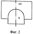
На Фиг.2 показана схема расположения преформы и шлифовальника, где 9 - заготовка, 10 - шлифовальник.Figure 2 shows the layout of the preform and the grinder, where 9 is the workpiece, 10 is the grinder.
На Фиг.3 показана принципиальная схема механизма тонкой полировки - автокопира, где 11 - основание-наклеечник, 12 - полировальник, 13 - система блоков съемных грузов-противовесов. Стрелками указаны направления движения отдельных частей автокопира.Figure 3 shows a schematic diagram of the mechanism of fine polishing - a copy machine, where 11 is the base-nakleechnik, 12 is a polisher, 13 is a system of blocks of removable counterweights. Arrows indicate the direction of movement of individual parts of the autocopy.
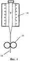
На Фиг.4 показана схема перетягивания преформы в дроты, где 9 - преформа, помещенная в электрическая печь 14, 15 - вытягивающий механизм, 16 - дрот - блок-заготовка для нарезки цилиндрических микролинз.Figure 4 shows a diagram of dragging a preform into drills, where 9 is a preform placed in an
На Фиг.5 показан эскиз преформы, где а) - вид преформы сверху с обозначенными на ней пропилами 17, 18 и 19, которые определяют места измерения отклонения фокусного отрезка от номинала. 20 - запил преформы для подвески ее на вытягивающий механизм 15 установки перетягивания (см. фиг.4); б) - вид преформы сбоку, у которой выполнена асферическая - эллиптическая поверхность 21. На чертеже преформы (вид а)) обозначены ее длина - L и ширина - В, а на виде сбоку - б) - общая высота плеча Н и h - высота плеча до начала образования ее асферической поверхности.Figure 5 shows a sketch of the preform, where a) is a top view of the preform with the
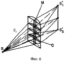
На Фиг.6 изображена схема работы цилиндрической линзы, где М - меридиональное сечение, С - сагиттальное сечение, S - фокусное расстояние от источника излучения, S'1 и S'2 - фокусные расстояния от соответствующих участков сагиттального сечения микролинзы.Figure 6 shows a diagram of a cylindrical lens, where M is the meridional section, C is the sagittal section, S is the focal length from the radiation source, S ' 1 and S' 2 are the focal lengths from the corresponding sections of the sagittal section of the microlens.
На Фиг.7 показано отклонение фокусного отрезка по профилю (по сечению) готовой преформы для асферических линз от номинала (пример на S1=1,53) в указанных на Фиг.5 местах пропилов 17, 18 и 19 в координатах: Y=S' - фокус, X - точки измерения от вершины эллипса.Figure 7 shows the deviation of the focal length along the profile (cross-section) of the finished preform for aspherical lenses from the nominal value (example in S 1 = 1.53) at the locations of
На Фиг.8 представлен чертеж готовой асферической линзы, где а) - вид сбоку с высотой общего плеча линзы Н' и h' - высота плеча линзы до начала образования ее асферической поверхности. Вид б) - вид линзы сверху, длина которой обозначена L' и ширина - В'.On Fig presents a drawing of a finished aspherical lens, where a) is a side view with the height of the common shoulder of the lens H 'and h' is the height of the shoulder of the lens before the formation of its aspherical surface. View b) is the top view of the lens, the length of which is indicated by L 'and the width by B'.
Пример. Цилиндрическая асферическая микролинза изготавливалась из оптического стекла ТБФ10. (Бесцветное оптическое стекло СССР. Каталог. Москва 1990 г.), показатель преломления стекла Ne=1.82057.Example. A cylindrical aspherical microlens was made of TBF10 optical glass. (Colorless optical glass of the USSR. Catalog. Moscow 1990), glass refractive index N e = 1.82057.
Заготовка преформы 9 изготовлялась из квадратного штабика размером □23×23÷□26×26 мм, длиной 350-400 мм на шлифовальном станке.The
Ширина заготовки выполнена размером Взагот=20±0,2 мм, а две боковые противоположные грани заготовки перпендикулярны основанию.The width of the workpiece is made in size B zagot = 20 ± 0.2 mm, and two side opposite sides of the workpiece are perpendicular to the base.
Одна из боковых граней, которая впоследствии будет отполирована, является базовой для дальнейшей установки шлифовальника и самой заготовки.One of the side faces, which will subsequently be polished, is the base for further installation of the grinder and the workpiece itself.
Верхней поверхности заготовки, параллельной основанию, которой в дальнейшем будет придаваться асферическая форма шлифовальником, придали форму полусферы с диаметром ⌀полусферы=Взагот.=20±0,2 мм по всей длине заготовки. Эту обработку производили на алмазной планшайбе.The upper surface of the workpiece, parallel to the base, which will subsequently be given an aspherical shape by a grinder, has been shaped into a hemisphere with a diameter of ⌀ hemisphere = In the bar. = 20 ± 0.2 mm along the entire length of the workpiece. This treatment was performed on a diamond faceplate.
Механическую обработку сферической поверхности проводят путем наложения на заготовку 9 шлифовальника 10, имеющего изнутри форму заданной поверхности преформы (Фиг.2), возвратно-поступательными продольными перемещениями шлифовальника 10 под давлением 150-200 г/мм2.The machining of the spherical surface is carried out by applying to the
Боковые поверхности заготовки шлифовали шлифпорошками от №12 (120 мкм) до М 14 (10-14 мкм) включительно, одну из боковых граней (⊥ основанию) - полировали.The side surfaces of the workpiece were ground with grinding powders from No. 12 (120 μm) to M 14 (10-14 μm) inclusive, one of the side faces (⊥ to the base) was polished.
Разница значения ширины заготовки после обработки, по всей ее длине, не превышала 0,05 мм.The difference in the value of the width of the preform after processing, over its entire length, did not exceed 0.05 mm.
Обработка заготовки включала 4 операции, перечисленные ниже в таблице.The workpiece processing included 4 operations, listed in the table below.
Время обработки шлифпорошком: №12 (120 мкм) - от 1 до 1,5 часов, №3 - от 1 до 1,5 часа, М40~1,5 часа, М28-30 мин.Processing time with grinding powder: No. 12 (120 microns) - from 1 to 1.5 hours, No. 3 - from 1 to 1.5 hours, M40 ~ 1.5 hours, M28-30 minutes.
Развернули шлифовальник на 180° и обрабатывали заготовку шлифпорошком М28 еще - 30 мин. Суммарное время обработки заготовки шлифпорошком М28=1 час.The grinder was turned through 180 ° and the workpiece was processed with M28 grinding powder for another 30 minutes. The total processing time of the workpiece with grinding powder M28 = 1 hour.
Обработку шлифпорошком М14 проводили ~50 мин.Processing with M14 grinding powder was carried out for ~ 50 min.
После обработки преформу сняли со станка и промыли - ацетоном, спиртоэфирной смесью и водой.After processing, the preform was removed from the machine and washed with acetone, an alcohol-ether mixture and water.
Подогнали высоту преформы до размера Н=17-0,1 мм.We adjusted the height of the preform to a size of H = 17-0.1 mm.
Повторно преформу установили на станок и дополнительно шлифовали эллиптическую поверхность для устранения дефектов шлифовки в виде продольных полос на специальном приспособлении никелевой лентой-фольгой (зерно - 10-14 мкм) возвратно-поступательными движениями, но в поперечном направлении по 1,5 мин с каждой стороны.The preform was reinstalled on the machine and an additional elliptical surface was polished to eliminate grinding defects in the form of longitudinal strips on a special device with nickel-foil tape (grain - 10-14 microns) in reciprocating movements, but in the transverse direction for 1.5 minutes on each side .
Затем эллиптическую поверхность преформы полировали церитом (оксид церия 99%; зернистость 0,7-1,2 мкм).Then the elliptical surface of the preform was polished with cerite (cerium oxide 99%; grain size 0.7-1.2 μm).
Полировка преформы осуществляется на основании - наклеечнике 11 (Фиг.3), зажатом в центрирующем устройстве (не показано). Войлочный полировальник 12, вращающийся со скоростью 200-250 об/мин, уравновешенный грузами 13, полностью огибает сформированную шлифованием поверхность заготовки 9, которая кроме колебательного движения вокруг оси совершает возвратно-поступательные движения вдоль продольной оси. Таким образом, сама заготовка является копиром при ее полировке.Polishing the preform is carried out on the basis of the nakleechnik 11 (Figure 3), sandwiched in a centering device (not shown). Felt polishing
Полировка велась четыре часа, после чего преформа 9 снималась со станка, промывалась и проводился контроль геометрических размеров и асферической поверхности 21 (контролировалось изменение фокусного отрезка по профилю (по сечению) готовой преформы от номинала) (Фиг.5).Polishing was carried out for four hours, after which the
На одном конце преформы 9 изготавливался запил 20 для устройства подвески преформы в печь перетягивания 14 (см. Фиг.4), в которой нагревали преформу до температуры размягчения стекла (Т=745-750°С, логарифм вязкости Lgη~8, η-пуаз) и с помощью вытягивающего механизма 15 производили вытягивание дротов 16 длиной 0.7-1.0 м. Затем дроты 16, имеющие форму линзы с асферической поверхностью, разрезали на отрезки 100-200 мм, помещали в специальные кассеты и в вакуумной установке наносили просветляющие покрытия для рабочих длин волн. Затем готовые заготовки разрезали на микролинзы с заданными параметрами. Получено было 40000 микролинз, каждая длиной 2,6 мм, шириной 0,55 мм, высотой 0,41 мм. Асферическая поверхность полученных изделий описывается формулой y2=16х-0,606х2 (см. Фиг.5). Качество поверхности отвечает заданным требованиям: шероховатость Rz=0.04-0.05, полное отсутствие царапин, выколов, точек.At one end of the
Были изготовлены цилиндрические асферические микролинзы других размеров, порядок изготовления сохранялся, изменялась только форма и размер обрабатывающего инструмента.Cylindrical aspherical microlenses of other sizes were made, the manufacturing order was maintained, only the shape and size of the processing tool changed.
Claims (4)
Priority Applications (1)
| Application Number | Priority Date | Filing Date | Title |
|---|---|---|---|
| RU2007127648/03A RU2355652C2 (en) | 2007-07-19 | 2007-07-19 | Method of producing high-precision cylindrical micro-lenses with various section profiles |
Applications Claiming Priority (1)
| Application Number | Priority Date | Filing Date | Title |
|---|---|---|---|
| RU2007127648/03A RU2355652C2 (en) | 2007-07-19 | 2007-07-19 | Method of producing high-precision cylindrical micro-lenses with various section profiles |
Publications (2)
| Publication Number | Publication Date |
|---|---|
| RU2007127648A RU2007127648A (en) | 2009-01-27 |
| RU2355652C2 true RU2355652C2 (en) | 2009-05-20 |
Family
ID=40543600
Family Applications (1)
| Application Number | Title | Priority Date | Filing Date |
|---|---|---|---|
| RU2007127648/03A RU2355652C2 (en) | 2007-07-19 | 2007-07-19 | Method of producing high-precision cylindrical micro-lenses with various section profiles |
Country Status (1)
| Country | Link |
|---|---|
| RU (1) | RU2355652C2 (en) |
Cited By (1)
| Publication number | Priority date | Publication date | Assignee | Title |
|---|---|---|---|---|
| RU2757976C1 (en) * | 2020-07-14 | 2021-10-25 | Александр Владимирович Репин | Fibre-optic liquid level indicator |
-
2007
- 2007-07-19 RU RU2007127648/03A patent/RU2355652C2/en active
Non-Patent Citations (1)
| Title |
|---|
| СУЛИМ А.В. Производство оптических деталей. - М.: Высшая школа, 1975, с.9-11. * |
Cited By (1)
| Publication number | Priority date | Publication date | Assignee | Title |
|---|---|---|---|---|
| RU2757976C1 (en) * | 2020-07-14 | 2021-10-25 | Александр Владимирович Репин | Fibre-optic liquid level indicator |
Also Published As
| Publication number | Publication date |
|---|---|
| RU2007127648A (en) | 2009-01-27 |
Similar Documents
| Publication | Publication Date | Title |
|---|---|---|
| US10471669B2 (en) | Reusable castings molds | |
| US9864108B2 (en) | Molds for making contact lenses | |
| CN1089580A (en) | Large size quartz glass tube, preform and manufacture method thereof and quartz glass optical fibre | |
| JP2022540321A (en) | Method for manufacturing hollow core fiber and method for manufacturing preform for hollow core fiber | |
| US5867327A (en) | Process for manufacturing cylindrical microlenses | |
| RU2355652C2 (en) | Method of producing high-precision cylindrical micro-lenses with various section profiles | |
| CN210038305U (en) | 355nm ultraviolet telecentric f-theta lens | |
| CN107470990A (en) | The processing method of sulphur based material aspherical lens | |
| CN103058511A (en) | Method of preparing of micro-optical elements | |
| CN114206792A (en) | Method for manufacturing hollow-core optical fiber and hollow-core optical fiber preform | |
| CN206833057U (en) | F θ object lens | |
| JP4898569B2 (en) | Method for producing lens or lens precursor | |
| US20190134931A1 (en) | Processing method and processing device for lens mold core | |
| US7413689B2 (en) | Lens element from diamond-turned thermoplastic resin | |
| CN111316179A (en) | Method and system for producing an ophthalmic lens | |
| Zhou et al. | Mechanism of brittle fracture in diamond turning of microlens array on polymethyl methacrylate | |
| DE112012003428T5 (en) | Method for molding optimized lenses and apparatus therefor | |
| US8850850B2 (en) | Meniscus lens of synthetic quartz glass and method for the production thereof | |
| US20220048803A1 (en) | Systems and methods for molding chalcogenide glass into a near-net shaped part | |
| CN1654380A (en) | Method for manufacturing press molding glass material and method for manufacturing optical components | |
| CN108274112A (en) | Hollow-core fiber conveying type ultraviolet laser micromachining device and processing method | |
| CN110900015B (en) | Multi-laser composite precision machining method for free-form surface optical lens | |
| RU2555183C1 (en) | Flat lens from leuco sapphire with focus of e waves | |
| RU2712680C1 (en) | Method of producing meniscus from lithium fluoride crystals | |
| Zhou et al. | Aspheric lens processing of chalcogenide glass via combined PGM-SPDT process |
Legal Events
| Date | Code | Title | Description |
|---|---|---|---|
| PC41 | Official registration of the transfer of exclusive right |
Effective date: 20130408 |