RU2355268C2 - Adjustable helmet shell - Google Patents
Adjustable helmet shell Download PDFInfo
- Publication number
- RU2355268C2 RU2355268C2 RU2007105497/12A RU2007105497A RU2355268C2 RU 2355268 C2 RU2355268 C2 RU 2355268C2 RU 2007105497/12 A RU2007105497/12 A RU 2007105497/12A RU 2007105497 A RU2007105497 A RU 2007105497A RU 2355268 C2 RU2355268 C2 RU 2355268C2
- Authority
- RU
- Russia
- Prior art keywords
- helmet
- fastening element
- parts
- protrusion
- sliding
- Prior art date
Links
Images


Classifications
-
- A—HUMAN NECESSITIES
- A42—HEADWEAR
- A42B—HATS; HEAD COVERINGS
- A42B3/00—Helmets; Helmet covers ; Other protective head coverings
- A42B3/32—Collapsible helmets; Helmets made of separable parts ; Helmets with movable parts, e.g. adjustable
- A42B3/324—Adjustable helmets
Abstract
Description
По настоящему изобретению испрашивается приоритет по предварительным заявкам на патент США № 60/587542 и 60/587541, поданным 14 июля 2004 года, которые включены в настоящее описание путем отсылки. Кроме того, к раскрытому в настоящем описании изобретению относится заявка РСТ № WO 2006/005183 "Регулируемый шлем", поданная одновременно с настоящей заявкой и включенная в настоящее описание путем отсылки.The present invention claims priority on provisional patent applications US No. 60/587542 and 60/587541, filed July 14, 2004, which are incorporated into this description by reference. In addition, disclosed in the present description of the invention relates to PCT application No. WO 2006/005183 "Adjustable helmet", filed simultaneously with this application and incorporated into this description by reference.
Область изобретенияField of Invention
Настоящее изобретение относится к шлемам и, в частности, к регулируемым шлемам.The present invention relates to helmets and, in particular, to adjustable helmets.
Предпосылки создания изобретенияBACKGROUND OF THE INVENTION
Шлемы для различных видов деятельности, включая занятия спортом и работу в опасных условиях, часто требуют наличия оболочки или защитной поверхности. Для соответствия различным формам и размерам головы человека может возникнуть потребность в шлемах большего или меньшего размера. Кроме того, в зависимости от вида деятельности, условий окружающей среды, внешнего вида и ряда других факторов, может возникнуть необходимость в подгонке шлема. В частности, человек, носящий шлем, может захотеть, чтобы шлем сидел плотнее или свободнее, в зависимости от обстоятельств, или, альтернативно, может захотеть изменить посадку шлема, например, во время игры, в зависимости от сезона и т.п.Helmets for various activities, including sports and work in hazardous conditions, often require a sheath or protective surface. To fit the various shapes and sizes of a person’s head, helmets may be needed for larger or smaller sizes. In addition, depending on the type of activity, environmental conditions, appearance and a number of other factors, it may be necessary to fit the helmet. In particular, the person wearing the helmet may want the helmet to sit tighter or looser, depending on the circumstances, or, alternatively, may want to change the helmet fit, for example, during a game, depending on the season, etc.
Регулируемые шлемы обычно содержат две секции, которые перемещаются для удлинения шлема. Например, в Патенте США № 4477929, выданном Mattsson, раскрывается регулируемый шлем, где процедура регулировки обычно требует отвертки для затягивания и отпускания винта. Отпускание винта позволяет регулировать шлем, затяжка винта удерживает шлем в конкретной конфигурации. Эта необходимость в дополнительных инструментах для регулировки шлема затрудняет его регулировку, когда нужных инструментов нет под рукой. Другие известные шлемы также имеют ограничения, делающие их трудными или неудобными в использовании.Adjustable helmets typically contain two sections that move to extend the helmet. For example, US Patent No. 4,477,929 to Mattsson discloses an adjustable helmet, where the adjustment procedure usually requires a screwdriver to tighten and loosen the screw. Releasing the screw allows you to adjust the helmet, tightening the screw holds the helmet in a specific configuration. This need for additional tools to adjust the helmet makes it difficult to adjust when the necessary tools are not at hand. Other known helmets also have limitations that make them difficult or inconvenient to use.
Соответственно, имеется потребность в альтернативных шлемах.Accordingly, there is a need for alternative helmets.
Сущность изобретенияSUMMARY OF THE INVENTION
В соответствии с широким аспектом настоящего изобретения, предлагается шлем, содержащий первую часть шлема, вторую часть шлема, примыкающую к первой части, при этом эти части соединены друг с другом с возможностью скольжения и выполнены с возможностью скольжения относительно друг друга вдоль первой оси для определения внутренней полости переменного объема, крепежный элемент, скрепляющий элемент, установленный в положении на первой части шлема, при этом скрепляющий элемент выполнен с возможностью скольжения между открытым и закрытым положениями, при этом скрепляющий элемент выполнен с возможностью скольжения вдоль второй оси в плоскости, проходящей по существу параллельно плоскости этого положения, при этом указанные первая и вторая оси не параллельны, и вторая часть шлема имеет ограничитель, являющийся ответным для скрепляющего элемента, причем скрепляющий элемент и ограничитель взаимодействуют для воспрепятствования движению первой части шлема относительно второй части шлема, когда скрепляющий элемент находится в закрытом положении.In accordance with a broad aspect of the present invention, there is provided a helmet comprising a first part of a helmet, a second part of a helmet adjacent to the first part, wherein these parts are slidingly connected to each other and configured to slide relative to each other along the first axis to define an internal cavity of variable volume, a fastening element, a fastening element installed in position on the first part of the helmet, while the fastening element is made to slide between open and closed on while the fastening element is made to slide along the second axis in a plane extending substantially parallel to the plane of this position, while the first and second axes are not parallel, and the second part of the helmet has a limiter that is responsive to the fastening element, and the fastening element and the limiter cooperate to obstruct the movement of the first part of the helmet relative to the second part of the helmet when the fastening element is in the closed position.
Для удобства, согласно настоящему изобретению, может предлагаться шлем, содержащий переднюю часть и заднюю часть, которые определяют объем, в который входит голова пользователя, при этом первая часть содержит противолежащие первую и вторую боковые части, а задняя часть содержит противолежащие третью и четвертую боковые части, при этом первая боковая часть имеет такую конфигурацию и положение, чтобы примыкать к третьей боковой части, а вторая боковая часть имеет такую конфигурацию и положение, чтобы примыкать к четвертой боковой части, при этом первая часть зацеплена с возможностью скольжения с задней частью так, что указанный объем имеет возможность изменяться, при этом первая боковая часть содержит углубление, имеющее дно, и углубление содержит полость, расположенную на дне, при этом полость содержит разнесенные друг от друга боковые кромки, скрепляющий элемент, имеющий конфигурацию и положение, позволяющие ему сцепляться с возможностью скольжения в этом углублении, при этом скрепляющий элемент выполнен с возможностью перемещения между открытым и закрытым положениями, при этом скрепляющий элемент содержит основание и опору, выступающую вбок от него, при этом опора имеет размер и конфигурацию, позволяющие ей проходить сквозь полость, при этом опора содержит противоположные крылья, расположенные для скользящего зацепления с указанными кромками, при этом опора содержит по меньшей мере один выступ, отходящий от нее от указанного основания, при этом третья боковая часть содержит ограничитель, содержащий выполненное в нем отверстие, при этом третья боковая часть имеет размер, превышающий указанную полость, и отверстие расположено так, чтобы перекрывать с возможностью взаимодействия эту полость, при этом отверстие содержит первое и второе разнесенные друг от друга углубления на своей нижней кромке, при этом каждое из углублений имеет размер, позволяющий запираемым образом зацепляться с выступом, при этом полость, отверстие, скрепляющий элемент и ограничитель имеют такие конфигурации и размеры, что, когда выступ запираемым образом зацеплен в первом углублении, указанный объем отличается от объема, когда выступ запираемым образом зацеплен во втором углублении.For convenience, according to the present invention, a helmet may be provided comprising a front portion and a rear portion that define the volume into which the user's head enters, the first portion comprising opposing first and second side portions, and the rear portion comprising opposing third and fourth side portions while the first side part has such a configuration and position so as to adjoin the third side part, and the second side part has such a configuration and position so as to adjoin the fourth side part, pr and the first part is engaged with the possibility of sliding with the rear part so that the indicated volume can be varied, while the first side part contains a recess having a bottom, and the recess contains a cavity located at the bottom, while the cavity contains spaced apart side edges a fastening element having a configuration and position that allows it to engage with the possibility of sliding in this recess, while the fastening element is arranged to move between open and closed positions wherein the fastening element contains a base and a support protruding laterally from it, while the support has a size and configuration that allows it to pass through the cavity, while the support contains opposite wings located for sliding engagement with these edges, while the support contains at least at least one protrusion extending from it from the specified base, while the third side part contains a limiter containing a hole made in it, while the third side part has a size exceeding the specified cavity and the hole is arranged so as to overlap this cavity with the possibility of interaction, while the hole contains first and second recesses spaced from each other at its lower edge, while each of the recesses has a size that locks into engagement with the protrusion, while the cavity, the hole, the fastening element and the stopper have such configurations and dimensions that when the protrusion is locked in a lockable manner in the first recess, said volume is different from the volume when the protrusion is locked in a lockable manner in the second deepening.
Согласно другому варианту настоящего изобретения предлагается регулировочный механизм для шлема, имеющего первую часть, вторую часть, соединенную с первой частью, при этом части шлема выполнены подвижными относительно друг друга, при этом регулировочный механизм содержит скрепляющий элемент, установленный на первой части шлема и выполненный с возможностью скольжения по первой части шлема, при этом скрепляющий механизм содержит по меньшей мере один выступ, и ограничитель, расположенный на второй части шлема и являющийся ответным для скрепляющего элемента, при этом скрепляющий элемент и ограничитель взаимодействуют для предотвращения движения первой части шлема относительно второй части шлема, когда скрепляющий элемент перемещен во взаимодействующий контакт с ограничителем, при этом ограничитель определяет углубление для зацепления с выступом, когда скрепляющий элемент сдвинут во взаимодействующий контакт с ограничителем.According to another embodiment of the present invention, there is provided an adjusting mechanism for a helmet having a first part, a second part connected to the first part, while the parts of the helmet are movable relative to each other, the adjustment mechanism comprising a fastening element mounted on the first part of the helmet and configured to sliding along the first part of the helmet, while the fastening mechanism contains at least one protrusion, and a limiter located on the second part of the helmet and which is responsive to the replication element, wherein the fastening element and the stopper interact to prevent the first part of the helmet from moving relative to the second part of the helmet when the fastening element is moved into interacting contact with the stopper, while the stopper defines a recess for engagement with the protrusion when the fastening element is shifted into interacting contact with the stopper .
Другие и дополнительные преимущества и признаки настоящего изобретения будут очевидны специалистам из последующего подробного описания его вариантов со ссылками на прилагаемые чертежи.Other and additional advantages and features of the present invention will be apparent to those skilled in the art from the following detailed description of its options with reference to the accompanying drawings.
Краткое описание чертежейBrief Description of the Drawings
Настоящее изобретение будет более понятно из нижеследующего подробного описания его вариантов со ссылками на чертежи, на которых:The present invention will be more clear from the following detailed description of its options with reference to the drawings, in which:
Фиг.1 - изометрический вид регулируемого шлема по настоящему изобретению;Figure 1 is an isometric view of an adjustable helmet of the present invention;
Фиг.2 - шлем по фиг.1, в раздвинутом положении;Figure 2 - helmet of figure 1, in an extended position;
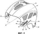
Фиг.3 - отдельный изометрический вид задней части шлема по фиг.1;Figure 3 is a separate isometric view of the rear of the helmet of figure 1;
Фиг.4 - отдельный вид скрепляющего элемента шлема по фиг.1;Figure 4 is a separate view of the fastening element of the helmet of figure 1;
Фиг.5 - вид с торца скрепляющего элемента по фиг.4;Figure 5 is an end view of the fastening element of figure 4;
Фиг.6 - отдельный вид снизу скрепляющего элемента по фиг.4;6 is a separate bottom view of the fastening element of figure 4;
Фиг.7 - изометрический вид шлема по фиг.1, где скрепляющий элемент удален;Fig.7 is an isometric view of the helmet of Fig.1, where the fastening element is removed;
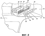
Фиг.8 - часть шлема по фиг.1, где скрепляющий элемент находится в открытом положении;Fig.8 is a part of the helmet of Fig.1, where the fastening element is in the open position;
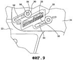
Фиг.9 - деталь фиг.8, где скрепляющий элемент находится в закрытом положении;Fig.9 is a detail of Fig.8, where the fastening element is in the closed position;
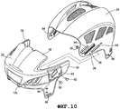
Фиг.10 - разнесенный вид передней и задней частей шлема по фиг.1;Figure 10 is an exploded view of the front and rear parts of the helmet of figure 1;
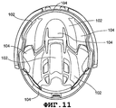
Фиг.11 - вид снизу шлема по фиг.1 в сдвинутом положении;11 is a bottom view of the helmet of figure 1 in a shifted position;
Фиг.12 - вид снизу шлема по фиг.1 в раздвинутом положении.12 is a bottom view of the helmet of FIG. 1 in an extended position.
Подробное описание изобретенияDETAILED DESCRIPTION OF THE INVENTION
На разных чертежах одинаковые детали обозначены одинаковыми позициями. На фиг.1 показан регулируемый шлем по варианту настоящего изобретения. Регулируемый шлем 20 содержит части 22 и 24. Передняя часть 22 шлема выполнена подвижной относительно задней части 24 по существу в направлении вперед-назад. Передняя часть 22 шлема содержит скрепляющий элемент 26, сконфигурированный и расположенный для взаимодействия с ограничителем 28 (см. фиг.3) для предотвращения перемещения частей 22 и 24 шлема относительно друг друга, когда скрепляющий элемент 26 находится в закрытом положении. Части 22 и 24 шлема показаны на фиг.1 в сдвинутом положении. Хотя на фиг.1-12 иллюстрируют шлем 20, где задняя часть 24 расположена с возможностью скольжения поверх передней части 22, очевидно, что в настоящем изобретении может использоваться и противоположная конфигурация.In different drawings, like parts are denoted by like reference numerals. 1 shows an adjustable helmet according to an embodiment of the present invention. The
На фиг.2 показан скрепляющий элемент 26, расположенный в открытом положении, и части 22 и 24 шлема раздвинуты, располагаясь дальше друг от друга, чем показано на фиг.1, и направление их перемещения показано стрелкой В. Перевод скрепляющего элемента 26 в открытое положение позволяет частям 22 и 24 шлема перемещаться относительно друг друга. Такое относительное перемещение позволяет частям шлема перемещаться по существу вдоль продольной оси шлема 20, как показано стрелкой В. Раздвигание частей 22 и 24 шлема друг от друга служит для увеличения внутреннего объема, определяемого шлемом 20. Этот увеличенный объем позволяет носить шлем пользователям с большим размером головы. Наоборот, сдвигание частей 22 и 24 друг к другу служит для уменьшения внутреннего объема, определенного шлемом 20. Такой уменьшенный объем позволяет носить шлем пользователям с меньшим размером головы. Такая регулировка позволяет пользователю носить шлем с большим комфортом и позволяет подгонять шлем для разных пользователей. Такая регулировка также может позволить пользователю увеличивать или уменьшать объем, определяемый шлемом 20, для увеличения или уменьшения зазора между шлемом 20 и головой пользователя.Figure 2 shows the
В нижеследующем описании различных вариантов шлема, если шлем содержит более чем один данный признак, будет описан только один такой признак. Например, шлем 20, как показано на фиг.1, может иметь скрепляющий элемент 26, расположенный на обеих сторонах шлема 20. Однако описание будет сфокусировано только на одном из скрепляющих элементов. В некоторых случаях другие подобные компоненты могут быть не идентичны описанным. Например, два таких скрепляющих элемента могут быть сконфигурированы как зеркальное отражение друг друга. Тем не менее, следует понимать, что описание одного относится и к другому (другим) без существенных изменений. Альтернативно, оболочка шлема по настоящему изобретению может содержать только один скрепляющий элемент 26, расположенный на одной или на другой из боковых сторон шлема.In the following description of the various helmet options, if the helmet contains more than one given feature, only one such feature will be described. For example, the
Когда части 22 и 24 шлема раздвигаются друг от друга или сдвигаются друг к другу до требуемого относительного расположения, скрепляющий элемент 26 можно перемещать вручную из открытого положения, показанного на фиг.2, в закрытое положение, показанное на фиг.1. Когда скрепляющий элемент находится в закрытом положении, он зацеплен за ограничитель 28 для предотвращения движения частей 22 и 24 шлема. Такое заблокированное движение позволяет шлему 20 лучше противостоять ударам, передавая силу удара на весь шлем 20. Если скрепляющий элемент 26 находится в открытом положении, то части 22 и 24 шлема можно сдвинуть ближе друг к другу, если к обеим частям 22 и 24 приложить силу. Движение частей 22 и 24 шлема друг к другу может привести к зажиму этих частей на голове пользователя, создавая дискомфорт и, возможно, причиняя боль. Дополнительно, когда скрепляющий элемент 26 находится в открытом положении, части 22 и 24 могут двигаться относительно друг друга. Это движение может привести к увеличению объема, определяемого шлемом 20, что позволит легче сбить или иным образом снять шлем с головы пользователя. Это снятие является нежелательным, например, если шлем 20 нужен для защиты.When the
В варианте настоящего изобретения комбинация скрепляющего элемента 26 и ограничителя 28 объединена со вторым скрепляющим элементом и ограничителем (не показаны). Соответствующие скрепляющие элементы и ограничители могут располагаться на противоположных сторонах шлема 20 и могут находиться напротив друг друга в поперечном направлении. По мере необходимости на шлем могут быть добавлены дополнительные комбинации скрепляющего элемента и ограничителя (не показаны).In an embodiment of the present invention, the combination of
Передняя часть 22 шлема содержит по меньшей мере один, предпочтительно два, налагаемых участка 30 (т.е. первый боковой участок и второй боковой участок, показанные на фиг.10) и по меньшей мере один вставляемый участок 32. Шлем 20 первоначально может собираться путем установки вставляемого участка 32 (который в одном из вариантов находится между налагаемыми участками 30) в сводчатую заднюю часть 24. Одновременно, налагаемые участки 30 могут выровняться на выпуклой стороне задней части 24 шлема. Такая конструкция позволяет передней и задней частям 22 и 24 шлема перемещаться относительно друг друга. Части 22 и 24 предпочтительно имеют конфигурацию, позволяющую обеспечить скользящее зацепление друг с другом, хотя возможны и другие конфигурации, например, без скользящего зацепления вставляемого участка 32. Задняя часть 24 шлема содержит третий и четвертый боковые участки 31 и 33, как лучше всего показано на фиг.3.The
Как показано на фиг.1 и 2, задняя часть 24 имеет конфигурацию больше, чем передняя часть 22 шлема. Альтернативно, относительные размеры частей 22 и 24 могут быть изменены, и передняя часть 22 может быть больше, чем задняя часть 24.As shown in FIGS. 1 and 2, the
Части 22 и 24 шлема показаны как имеющие конфигурацию "передняя-задняя". Альтернативно, части шлема можно сконфигурировать по-другому, включая несимметричные конфигурации. Например, части шлема можно сконфигурировать для интерфейса по продольной оси шлема 20. Такая конструкция может обеспечить возможность регулировки объема, определяемого шлемом 20, по ширине, по существу вдоль поперечной оси (не показана).
Скрепляющий элемент 26 может размещаться на налагаемом участке 30, а ограничитель 28 может размещаться на задней части 24 шлема, примыкая к налагаемому участку 390, т.е. на третьем боковом участке 31 и на четвертом боковом участке 33. Как показано на чертежах, скрепляющий элемент 26 может быть расположен так, чтобы входить или по существу входить в углубление 43, расположенное или размещенное на налагаемом участке 30. Альтернативно, скрепляющий элемент 26 может размещаться внутри задней части 24 шлема, при этом скрепляющий элемент 26 расположен на налагаемом участке 30. В другом альтернативном варианте скрепляющий элемент 26 и ограничитель 28 могут соответственно располагаться на одном вставляемом участке 32 и на соответствующем участке задней части 24 шлема.The
Можно сконфигурировать шлем 20 так, чтобы передняя часть 22 шлема полностью налагалась на заднюю часть 24 шлема. Альтернативно, передняя часть 22 может быть сконфигурирована так, чтобы полностью вставляться под заднюю часть 24. Возможны некоторые комбинации вышеописанных вариантов при соответствующих модификациях скрепляющего элемента 26 и ограничителя 28.You can configure the
На фиг.3 отдельно показан ограничитель 28. Ограничитель 28 может быть выполнен заодно с частью 24 шлема и может определять по меньшей мере один паз 34. Паз 34 может принимать ответный участок (подробно описанный ниже) скрепляющего элемента 26 для предотвращения относительного перемещения частей 22 и 24 шлема. Ограничитель 28 также определяет проход 36, позволяющий двигаться ответному участку скрепляющего элемента 26, выходя из паза 34, позволяя частям 22 и 24 шлема двигаться относительно друг друга. В настоящем варианте паз 34 и проход или отверстие 36 показаны как отверстия в части 24 шлема. Предпочтительно паз 34 имеет длину от 3 до 10 мм, обеспечивающую возможность перемещения частей шлема относительно друг друга на такую же величину.3, the
Однако их следует определить только как углубления или пазы, достаточные для обеспечения возможности зацепления и движения скрепляющего элемента 26. Как показано на чертежах, паз 34 расположен ниже прохода 36, хотя возможна и обратная конфигурация, а также другие варианты взаимного расположения.However, they should only be defined as recesses or grooves sufficient to allow engagement and movement of the
На фиг.3 также показано множество пазов 34, определенных по существу параллельными пальцами 38. Пазы 34 образуют гнезда для зацепления скрепляющего элемента 26. Когда скрепляющий элемент 26 находится в открытом положении, он имеет возможность перемещения по проходу 36, когда участки 24 и 26 шлема движутся относительно друг друга. Когда достигнуто желаемое взаимное положение частей 22 и 24 шлема, скрепляющий элемент можно переместить в закрытое положение для зацепления со смежными пальцами 38 прохода 36. Когда скрепляющий элемент 26 входит в такое зацепление, движение части 22 шлема, с которой соединен скрепляющий элемент 26, блокируется.3 also shows a plurality of
Относительный размер и положение пальцев 38 может использоваться для изменения степени относительно смещения частей 22 и 24 шлема. Например, более узкие пальцы 38 и/или пазы 34 могут обеспечить возможность более тонкой регулировки объема шлема 20. Если пальцы 38 имеют такую конфигурацию, которая показана на чертежах, придется использовать достаточное количество материала, чтобы предотвратить нежелательный изгиб, деформацию или поломку пальца 38, когда к одной или к обеим из частей 22, 24 шлема прилагается сила, когда скрепляющий элемент 26 находится в закрытом положении. Пластмасса, которую можно использовать для настоящего изобретения, является обычной пластмассой, широко применяемой в производстве шлемов и спортивного инвентаря. Однако следует понимать, что вместо применяемой в настоящее время пластмассы, дополнительно или в комбинации с ней можно применять и другие материалы. Хотя для создания скрепляющего элемента 26 и ограничителя 28 можно применять пластмассу или полимеры, для создания пальцев, определяющих пазы, расположенные ближе друг другу для более тонкой регулировки, можно применять более прочные материалы, например металл. Такие альтернативные материалы предпочтительно могут использоваться как вставки в часть 24 шлема так, что другие детали шлема 20 не обязательно делать из того же материала. В одном варианте настоящего изобретения ширина пальцев 38 составляет от приблизительно 0,5 мм до приблизительно 5,0 мм, а длина - от приблизительно 0,5 мм до приблизительно 10 мм. Ширина пазов составляет от приблизительно 0,5 мм до приблизительно 5,0 мм, а длина - от приблизительно 0,5 мм до приблизительно 10. Следует понимать, что эти размеры могут быть больше или меньше. Размеры каждого паза 34 и/или пальца 38 не обязательно должны быть одинаковыми. Разные интервалы, высоты и габариты могут обеспечить возможность переменной степени регулировки в отличие от показанного варианта ограничителя 28.The relative size and position of the
В показанном варианте выполнено тринадцать пальцев. Пальцы 38 могут быть разнесены, чтобы обеспечить возможность максимального перемещения частей 22 и 24 шлема приблизительно на 10-15 мм. Удлинение ограничителя 28 может увеличить длину максимального перемещения частей 22 и 24 шлема. Наоборот, уменьшение длины ограничителя 28 может ограничить диапазон перемещения частей 22 и 24 шлема относительно друг друга.In the shown embodiment, thirteen fingers are made. The
Как показано на фиг.3, ограничитель 28 наклонен приблизительно на 20-40° от горизонтали Н (горизонталь определяется ориентацией шлема при его ношении). Ограничитель 28 может располагаться горизонтально. В конкретном варианте угол наклона ограничителя 28 может быть таким, чтобы максимально облегчить относительное перемещение частей 22 и 24 шлема. Какова бы ни была ориентация ограничителя 28, пазы 34 имеют конфигурацию, обеспечивающую зацепление со скрепляющим элементом 26, когда он перемещается между закрытым и открытым положениями, чтобы предотвратить перемещение частей 22 и 24 шлема.As shown in figure 3, the
В показанном на чертежах варианте пальцы 38 сцепляются со скрепляющим элементом 26. Поскольку скрепляющий элемент 26 установлен на передней части 22 шлема, относительное движение передней части 22 шлема также блокировано. Для достижения этого движение скрепляющего элемента 26, например, по существу по оси А (см. фиг.2), не может быть параллельно движению передней части 22 шлема по существу в направлении оси В. Скрепляющий элемент 26 выполнен подвижным по поверхности шлема 20 по существу по оси А. Это движение не должно быть идеально линейным и может выполняться по кривой, например, по кривой, по существу конгруэнтной кривизне участка шлема 20, примыкающего к скрепляющему элементу 26. Такая конструкция позволяет передавать силу, прилагаемую к одной части шлема, на другую часть шлема через скрепляющий элемент 26, когда скрепляющий элемент 26 находится в закрытом положении. Такая конструкция может обеспечить дополнительную защиту пользователя шлема 20.In the embodiment shown, the
В показанном варианте ограничитель 28 содержит пальцы 38 для зацепления со скрепляющим элементом 26. Конкретная конфигурация пальцев 38 может быть модифицирована, при сохранении зацепления с ответной деталью скрепляющего элемента 26 для предотвращения относительного перемещения частей 22 и 24 шлема. Например, пальцы 38 могут быть сформированы как по существу треугольные зубья (не показаны) для приема ответной детали скрепляющего элемента 26. В другом альтернативном варианте ограничитель 28 может включать поверхность или материал для фрикционного зацепления со скрепляющим элементом 26. Например, деформируемая вспененная резина (не показана) ограничителя 28 может иметь конфигурацию, обеспечивающую возможность зацепления с ответной резиновой поверхностью скрепляющего элемента 26, так что, когда скрепляющий элемент 26 находится в закрытом положении, ответные детали из вспененной резины сжимаются и фрикционно зацепляются для воспрепятствования относительному перемещению частей 22 и 24 шлема. Альтернативно, скрепляющий элемент 26 может иметь зубцы или какую-либо другую деталь для зацепления с другого типа деталью ограничителя 28, например со вспененной резиной. В другом альтернативном варианте ограничитель 28 может иметь одну половину липучки Velcro®, а скрепляющий элемент 26 - другую половину липучки Velcro® для разъемного взаимодействия с ограничителем 28.In the shown embodiment, the
Как показано на фиг.4, 5 и 6, скрепляющий элемент 26 содержит по меньшей мере один, предпочтительно более чем один, выступ 40. Выступы 40 могут отходить от скрепляющего элемента 26 не параллельно направлению пальцев 38. Этот по меньшей мере один выступ 40 выполнен с возможностью частично размещаться в пазу 34 ограничителя, когда скрепляющий элемент 26 переведен в закрытое положение, поскольку по меньшей мере часть каждого выступа 40 сконфигурирована с возможностью зацепления между пальцами 38 ограничителя 28. Выступы 40 могут быть удлиненными и могут отходить от корпуса 42 скрепляющего элемента 26. Альтернативно, скрепляющий элемент 26 вместо этого может содержать деталь, подобную пальцам ограничителя 28, где выступы скрепляющего элемента 26 отходят как пальцы, по существу параллельно пальцам 38, для зацепления между пальцами 38. В другом альтернативном варианте скрепляющий элемент 26 может содержать какую-либо другую деталь, например заостренный зуб (не показан), для зацепления с ответной деталью ограничителя 28, когда скрепляющий элемент 26 переведен в закрытое положение.As shown in FIGS. 4, 5 and 6, the
В одном варианте скрепляющий элемент 26 содержит шесть выступов, из которых два выступа 44 являются укороченными. Укороченные выступы 44 могут обеспечивать более свободное движение скрепляющего элемента 26 между открытым и закрытым положениями. Укороченные выступы 44 позволяют скрепляющему элементу 26 открыть проход 36 (см., например, фиг.8). Шлем 20 может быть сконфигурирован так, чтобы все выступы имели одинаковую длину или разные длины. Далее, в одном из вариантов выступов может быть больше или меньше шести.In one embodiment, the
Выступы 40 выполнены из материала, способного противостоять деформации при взаимодействии с ограничителем 28 и при приложении силы к шлему 20, например, во время игры. Скрепляющий элемент 26 может быть выполнен из того же материала, что и ограничитель 28 и остальные части шлема 20, или из другого материала. Альтернативно можно использовать разные материалы, такие как различные пластмассы, полимеры и другие материалы, включая сплав или металл, такой как алюминий, и их комбинации.The
Увеличенное сопротивление деформации может быть получено за счет конфигурирования скрепляющего элемента 26 и ограничителя 28 так, чтобы более чем один выступ 40 был зацеплен за более чем один палец 38 ограничителя 28. В показанном варианте все шесть выступов 40 могут зацепляться с соответствующими пальцами 38 в каждом из возможных положений регулировки частей 22 и 24 шлема, когда скрепляющий элемент 26 находится в закрытом положении. Соответственно, в шлеме 20 части 22 и 24 могут принимать девять разных положений относительно друг друга. Как указано выше, увеличение количества пазов 34 и/или уменьшение количества выступов 40 может применяться для изменения диапазона регулировок шлема 20.Increased deformation resistance can be obtained by configuring the
Как дополнительно показано на фиг.7, передняя часть 22 шлема может содержать отверстие или полость 45 для установки скрепляющего элемента 26. Скрепляющий элемент 26 может содержать держатель 46 для соединения скрепляющего элемента 26 с передней частью 22 шлема. Держатель 46 может содержать по меньшей мере одно крыло 48 для сцепления с кромкой отверстия 45. В одном варианте на скрепляющем элементе 26 заодно с ним выполнены два деформируемых крыла. Они могут быть изготовлены, например, методом литья под давлением. Крылья 48 разнесены друг от друга на расстояние, чуть больше, чем ширина отверстия 45. Деформируемые чуть более широкие крылья 48 можно с усилием протолкнуть сквозь отверстие 45, что приведет к временной деформации крыльев 48. Когда крылья 48 пройдут сквозь окно 45, они упруго возвращаются по существу в первоначальное положение для взаимодействия с корпусом 42 для зацепления с кромкой отверстия 45, препятствуя их извлечению из этого отверстия 45. Такую деформацию можно сделать достаточной для обеспечения возможности извлечения и замены скрепляющего элемента 26, чтобы чистить, ремонтировать или заменять детали шлема 20.As further shown in FIG. 7, the front of the
Отверстие 45 может иметь выровненные кромки 50 и 52, которые принимаются держателем 46. Ориентация кромок 50 и 52 обеспечивает возможность скользящего движения скрепляющего элемента 26 вдоль оси А между открытым и закрытым положениями. Альтернативно, кромки 50, 52 могут иметь пазы или ступени, позволяющие извлекать и заменять скрепляющий элемент 26 в одном или более положении так, что выступы 40 могут входить в зацепление и выходить из зацепления с ограничителем 28 по мере надобности. В другом альтернативном варианте отверстие 45 может быть сконфигурировано для предотвращения скользящего движения скрепляющего элемента 26. В таком варианте скрепляющий элемент 26 можно снять, затем отрегулировать шлем 20 и установить скрепляющий элемент на место для сохранения нового положения частей 22 и 24 шлема.The
Скрепляющий элемент 26 альтернативно может быть изготовлен из двух или более деталей и может устанавливаться путем установки структуры, включающей выступы 40, с одной стороны отверстия 45 в шлеме, и путем установки корпуса 42 скрепляющего элемента с другой стороны, и с дальнейшим склеиванием, свинчиванием или соединением другим способом этих двух деталей друг с другом для зацепления по меньшей мере с одной кромкой отверстия 45.The
Как описано выше, ограничитель 28 может быть установлен под углом к горизонтали Н. Аналогично, скрепляющий элемент 26 также может быть установлен так, чтобы выступы 40 совпадали с и зацепляли скрепляющий элемент 26.As described above, the
В одном варианте выступы 40 (или другой подходящий зацепляющий элемент) могут быть установлены на опоре 54 корпуса 43 скрепляющего элемента. От опоры 54 могут отходить, например, вбок крылья 48. Опора 54 может быть сконфигурирована так, чтобы иметь удерживающую деталь 56, определяющую канавку 58. Канавка 58 может принимать другую кромку 60 отверстия 45. Канавка 58 предпочтительно соответствует толщине кромки 60 так, что кромка 60 может быть в нее вставлена. Таким образом, понятно, что удерживающая деталь 56 может при использовании входить в скользящее зацепление с кромкой 60 так, что такое зацепление обеспечивает направление скрепляющего элемента 26 вверх и вниз. При работе кромка 60 может входить в канавку 58, когда скрепляющий элемент перемещен в закрытое положение. Эта деталь может дополнительно удерживать скрепляющий элемент 26 в отверстии 45. Опора 54 может дополнительно содержать удерживающую деталь в форме язычка 62. Язычок 62 вместе с корпусом 42 определяют углубление 64 для приема кромки, например кромки 66 отверстия 45. Язычок 62 может предотвращать извлечение скрепляющего элемента 26 из отверстия 45, когда скрепляющий элемент 26 находится в открытом положении, и язычок 62 зацеплен с кромкой 66 отверстия.In one embodiment, the protrusions 40 (or another suitable engaging member) may be mounted on a
Крылья 48 вместе с удерживающими деталями 56 и 64 обеспечивают возможность скользящего движения скрепляющего элемента 26, одновременно удерживая скрепляющий элемент 26 в отверстии 45. Таким образом, понятно, что скрепляющий элемент 26 удерживается в скользящем зацеплении с частью 22 шлема.The
Скрепляющий элемент 26 может иметь одно или более крыло 48, удерживающую деталь 56 и удерживающую деталь 62. Эти детали не обязательно должны располагаться точно так, как описано выше. В альтернативных вариантах могут применяться, например, крылья, установленные вместо язычков 62 и удерживающей детали 56. Более того, с данной кромкой отверстия 45, например с кромкой 66, может зацепляться множество язычков 62 или других подобных деталей.The
Как показано на фиг.6, каждое крыло 48 может проходить под углом к опоре 54 в направлении корпуса 42. Это дает некоторую степень упругости крыльев 48 для удержания кромки отверстия 45. Это также позволяет вводить производственные допуски.As shown in FIG. 6, each
На фиг.7 отверстие 45 показано имеющим форму, близкую к параллелограмму. Альтернативно, оно может иметь другую форму, например прямоугольную или криволинейную, которая должна обеспечить возможность сцепления скрепляющего элемента 26 и ограничителя 28. Отверстие 45 также предпочтительно достаточно велико, чтобы обеспечить возможность движения выступов 40 из ограничивающих пальцев, чтобы можно было регулировать положение частей 22 и 24 шлема (см. фиг.8, где выступы 40 могут освободить пальцы 38).7, the
Как показано на фиг.2, 4 и 7, скрепляющий элемент 26 дополнительно может быть оснащен деталью для предотвращения движения скрепляющего элемента 26, когда он зацеплен с ограничителем 28. Например, к ограничителю 28 может быть прикреплен или выполнен заодно с ним выступ 68. Выступ 68 может быть установлен на корпусе 42 и может проходить к передней части 22 шлема, когда на ней установлен скрепляющий элемент 26. Передняя часть 22 шлема может определять соответствующий паз 70 для приема выступа 68, когда скрепляющий элемент 26 находится в закрытом положении. При работе выступ 68 может иметь возможность скользить по поверхности передней части 22 шлема, или примыкая к ней, когда скрепляющий элемент движется из открытого положения в закрытое. В закрытом положении выступ 68 имеет возможность сесть в паз 70. Можно использовать множество таких выступов и пазов (пазы и выступы можно поменять местами или изменить так, чтобы один, или более, выступ располагался на шлеме 20, а соответствующие пазы были выполнены в скрепляющем элементе 26). В одном варианте второй выступ 72 может взаимодействовать со вторым пазом 74 передней части 22 шлема для дополнительного воспрепятствования движению скрепляющего элемента 26, когда он находится в закрытом положении. Выступ 68 может быть больше (или меньше), чем второй выступ 72. Выступ увеличенного размера (и соответствующий паз) может служить для создания увеличенного сопротивления движению скрепляющего элемента 26 из закрытого положения.As shown in FIGS. 2, 4 and 7, the
На передней части 22 шлема может быть выполнен один или более дополнительный паз 76 для приема выступа, такого как выступ 68, когда скрепляющий элемент 26 находится в открытом состоянии. Это способствует тому, что скрепляющий элемент 26 освобождает ограничитель 28, когда регулируется положение частей 22 и 24 шлема, что устраняет необходимость вручную удерживать скрепляющий элемент 26 в открытом положении.On the front of the
Как показано на фиг.7, в передней части 22 шлема может быть выполнен вырез 78 для приема по меньшей мере части корпуса 42 скрепляющего элемента. Корпус 42 может соответствовать кромкам 80 и 82 выреза 78. Кромки 80 и 82 предпочтительно совпадают, ориентированы, по оси движения скрепляющего элемента 26 между открытым и закрытым положениями, например по оси А. В такой конфигурации кромки 80 и 82 могут способствовать перемещению скрепляющего элемента 26 так, чтобы он освобождал ограничитель 28 в открытом положении и зацеплялся с ограничителем 28 в закрытом положении.As shown in FIG. 7, a
В зависимости от плотности посадки между ограничителем 28, скрепляющим элементом 26 и кромками 80, 82 выреза, скрепляющий элемент 26 может дополнительно оказывать сопротивление движению частей 22 и 24 шлема на интерфейсе, где он встречается с кромками 80 и 82, когда скрепляющий элемент 26 находится в закрытом положении. В одном варианте, когда скрепляющий элемент 26 находится в закрытом положении и к шлему 26 прилагается сила, эта сила передается между частями 22 и 24 шлема через опору 54 скрепляющего элемента 26, выступы 40 и пальцы 38. Сила также может передаваться между одной или обеими кромками выреза 80 и 82 и корпусом 42 скрепляющего элемента.Depending on the density of the fit between the
В альтернативном варианте скрепляющий элемент 26 может быть установлен на задней части 24 шлема для зацепления с соответствующим ограничителем, установленным на вставляемом участке 32.Alternatively, the
Еще в одном альтернативном варианте скрепляющий элемент 26 может быть установлен с возможностью скольжения на часть 22 шлема так, чтобы часть скрепляющего элемента 26 выступала за часть 22 шлема для зацепления с ограничителем, расположенным на непокрывающем участке задней части 24 шлема. Например, скрепляющий элемент можно установить с возможностью скольжения вдоль его кромки так, чтобы он выступал из налагаемого участка 30 для зацепления с ограничителем, расположенным на задней части 24 шлема. Этот вариант может работать по существу так же, как и вариант, показанный на чертежах. Скрепляющий элемент 26 также можно установить внутри шлема 20 на задней части 24 шлема, а ограничитель 28 можно установить на передней части 22 шлема.In yet another alternative embodiment, the
Возвращаясь к фиг.3, а также к фиг.10, части 22 и 24 шлема могут быть установлены друг на друге с возможностью скольжения. В задней части 24 шлема может быть определена по меньшей мере одна прорезь 84. В варианте настоящего изобретения прорезь 84 проходит сквозь часть 24 шлема. Однако прорезь 84 можно сконфигурировать как дополнительное или интегрально выполненное отверстие, отходящее от задней части 24 шлема. Сквозь переднюю часть 22 шлема можно вставить направляющую в форме пальца штифта 86, который входит в прорезь 84. Штифт 86 может удерживаться в прорези 84 за счет деформирования конца 88 штифта 86 (см. фиг.8 и 9). Штифт 86 альтернативно или дополнительно может содержать удерживающую деталь, предотвращающую извлечение штифта 86 из прорези 84. Например, на штифт 86 можно установить шайбу 90 и закрепить ее, например, деформировав конец штифта 86. В одном варианте штифт 86 может быть выполнен из металла, например из деформируемого и не подверженного коррозии металла, и по существу может иметь конструкцию заклепки.Returning to figure 3, as well as to figure 10,
Штифт 86 может быть постоянно закреплен на передней части 22 шлема или может быть выполнен отдельно от нее. В одном варианте штифт 86 содержит головку 92. Штифт 86 вставляется через отверстие 93, выполненное в передней части 22 шлема, которое пропускает штифт 86, но не пропускает головку 92, как показано на фиг.10. В другом варианте штифт 86 может быть выполнен заодно с передней частью 22 шлема.The
Прорезь 84 сконфигурирована так, чтобы обеспечить возможность скользящего перемещения передней и задней частей 22 и 24 шлема относительно друг друга для того, чтобы скрепляющий элемент 26 зацеплялся с ограничителем 28 по меньшей мере в одном и, предпочтительно, более чем в одном положении. Например, прорезь 84 может быть расположена и сконфигурирована так, чтобы совпадать с проходом 36 так, чтобы позволить скрепляющему элементу или заставить скрепляющий элемент беспрепятственно двигаться по проходу 36 в открытое положение, когда переднюю часть 22 шлема сдвигают относительно задней части 24 шлема. Скрепляющий элемент 26 затем можно селективно перевести в закрытое положение для зацепления с ограничителем 28 для удержания передней и задней частей шлема в предпочтительной относительной ориентации. Прорезь 84 имеет по существу продольную ось, которая ориентирована так, чтобы обеспечивать движение передней части 22 вдоль оси, соответствующей оси В.The
Прорезь 84, показанная на фиг.3, проходит по существу рядом с ограничителем 28. Альтернативно, она может быть расположена не рядом с ограничителем 28, но ориентирована параллельно подобной оси для обеспечения возможности или облегчения относительного перемещения частей шлема, как описано выше.The
Рядом с ограничителем 28 может быть выполнена дополнительная прорезь 94 аналогичной конфигурации. Прорезь 94 дополнительно служит для обеспечения перемещения частей 22 и 24 шлема для изменения объема, определяемого шлемом 20, для подгонки к разным размерам головы или в соответствии с предпочтениями пользователя. Прорезь 94 альтернативно может быть расположена рядом с прорезью 84 или в каком-либо другом положении на задней части 24 шлема, для обеспечения требуемого относительного перемещения частей 22 и 24 шлема.Next to the
Альтернативно, прорезь 84 (и/или прорезь 94) может располагаться на передней части 22 шлема, а соответствующий штифт, такой как штифт 86, может располагаться на задней части 24 шлема. Для крепления передней части 22 шлема к задней части 24 могут применяться и другие конструкции, такие как сформированные за одно целое выступы, отходящие от передней части 22 шлема и зацепленные с возможностью скольжения в прорези 84 защелкиванием.Alternatively, a slot 84 (and / or a slot 94) may be located on the front of the
Прорези, например прорезь 84, на своей продольной кромке дополнительно могут содержать выступ или подобную деталь (не показана). Участки между такими выступами могут быть расположены так, чтобы соответствовать пазам 34 ограничителя. Такая конструкция может обеспечить возможность более удобного положения выступов 40 скрепляющего элемента в пазах 34, поскольку штифт 86 будет размещаться между такими выступами.Slots, such as
В альтернативных вариантах части 22 и 24 шлема могут крепиться каким-либо другим способом, например на петле или на шарнирах. Такая конструкция может потребовать криволинейных или дугообразных деталей ограничителя 28 или скрепляющего элемента 26, чтобы они могли повторять путь движения передней части 22 шлема относительно задней его части 24.In alternative embodiments, the
Части 22 и 24 шлема альтернативно могут быть сформированы как одна деталь с деформируемой областью, расположенной между ними, которая обеспечивает возможность относительного перемещения этих двух частей. Детали этого шлема могут быть такими, как описано выше, с некоторыми модификациями.
Шлем 20, в зависимости от его назначения, может иметь дополнительные детали, такие как крепежные отверстия для ремня, надеваемого на подбородок, защита 98 для ушей и другие детали, такие как винты 100 для крепления маски.The
Как показано на фиг.8, скрепляющий элемент 26 в открытом положении может свободно двигаться в проходе 36. Выступы 40 могут перекрывать проход 36, чтобы дополнительно направлять движение частей 22 и 24 шлема относительно друг друга, когда скрепляющий элемент 26 находится в открытом положении. Альтернативно, выступы 40 сконфигурированы так, чтобы не перекрывать проход 36.As shown in FIG. 8, the
На фиг.9 показан скрепляющий элемент 26, зацепленный с ограничителем 28 для блокирования перемещения частей 22 и 24 шлема относительно друг друга. Частичное зацепление скрепляющего элемента 26 и ограничителя 28 также может в достаточной степени блокировать перемещение частей 22 и 24 шлема и заставить их оставаться на своих местах.Fig. 9 shows a
На фиг.11 и 12 показано относительное расположение частей 22 и 24 шлема в раздвинутом и сдвинутом положениях. Шлем 20 может содержать подшлемник 102 и/или защитный подшлемник 104. Как показано на чертежах, каждая часть 22 и 24 может содержать отдельный подшлемник так, чтобы подшлемник двигался с той частью 22 или 24, к которой он прикреплен.11 and 12 show the relative location of the
Шлем 20 можно регулировать непосредственно на голове пользователя или в снятом состоянии. Его можно регулировать вручную, без использования инструментов, например, держа в руках. Разумеется, шлем на пользователе может регулировать и другой человек. Скрепляющие элементы 26 перемещаются в открытое положение (в данном примере шлем 20 имеет два крепежных элемента 26 и соответствующие ограничители 28, расположенные на обеих сторонах шлема 20). Части 22 и 24 шлема затем можно перемещать относительно друг друга для уменьшения или увеличения объема, определяемого шлемом 20. Когда будет достигнуто желаемое относительное положение передней и задней частей 22 и 24 шлема, скрепляющий элемент 26 можно переместить в закрытое положение. Эта операция проводится для каждой комбинации скрепляющий элемент/ограничитель.The
Альтернативно, части 22 и 24 шлема можно раздвинуть, включая полное раздвижение, перед тем как надеть на голову пользователя. Это дает больший зазор при посадке на голову. Затем, на голове, части 22 и 24 шлема можно отрегулировать, как описано выше, чтобы обеспечить наилучшую посадку на голове пользователя.Alternatively, the
Если шлем 20 регулируется на голове, такую регулировку можно проводить аналогично. Скрепляющие элементы 26 переводятся в открытое положение, предпочтительно одновременно. После этого переднюю и заднюю части 22 и 24 шлема перемещают относительно друг друга до получения желаемой или удобной посадки. Затем скрепляющие элементы перемещают в закрытое положение. Эту процедуру можно выполнить, используя большие пальцы рук для перемещения скрепляющих элементов в открытое положение. Затем части 22 и 24 шлема можно отрегулировать относительно быстро и вернуть скрепляющий элемент в закрытое положение, сдвигая их руками приблизительно одновременно (либо перемещать скрепляющие элементы 26 и регулировать шлем 20 можно одной рукой). Этот процесс занимает несколько секунд и может проводиться даже, например, во время игры, по мере необходимости. В передней части 22 шлема можно выполнить углубление 106 для обеспечения доступа к кромке 108 скрепляющего элемента 26 (см. фиг.1 и 2). Затем к кромке 108 можно приложить силу для перемещения скрепляющего элемента 26 в открытое положение.If the
Как показано на фиг.10, передняя и задняя части 22 и 24 шлема можно собирать, первоначально вставляя направляющие 86 в переднюю часть 22 шлема. Затем переднюю и заднюю части 22 и 24 шлема можно собирать, вставляя направляющие 86 в прорези 84. После этого, на соответствующие штифты 86 надеваются шайбы 90, и концы 88 штифтов деформируются для удержания шайб 90. Затем устанавливают скрепляющие элементы 26, например, защелкивая их в отверстиях 45.As shown in FIG. 10, the front and
Части 22 и 24 шлема и скрепляющий элемент 26 предпочтительно выполнены из упруго деформируемой пластмассы, например пластмассы, формуемой в горячем состоянии, или из любой другой пластмассы, которая обычно используется для спортивного инвентаря, такого как футбольные шлемы, футбольные и хоккейные наплечники и т.п.The
Приведенное выше описание различных вариантов настоящего изобретения приведено в контексте хоккейного шлема. Тем не менее, различные варианты соответственно могут быть применены к шлемам других типов, включая шлемы для других видов спорта (футбол, лакросс, лыжи, скейтборд, роликовые коньки), для опасных условий работы или, возможно, но более редко, связанных с модой.The above description of various embodiments of the present invention is given in the context of a hockey helmet. However, various options can accordingly be applied to helmets of other types, including helmets for other sports (football, lacrosse, skiing, skateboard, roller skates), for hazardous working conditions or, perhaps, but more rarely, associated with fashion.
Хотя вышеприведенные компоненты настоящего изобретения были описаны достаточно подробно для ясности и понимания, специалистам понятно, что в конкретные варианты изобретения могут быть внесены различные модификации, изменения и адаптации, не выходящие за пределы объема прилагаемой формулы изобретения.Although the above components of the present invention have been described in sufficient detail for clarity and understanding, those skilled in the art will appreciate that various modifications, changes, and adaptations may be made to specific embodiments of the invention without departing from the scope of the appended claims.
Claims (36)
первую прорезь, определенную по меньшей мере одной из первой и второй частей шлема, и направляющую, расположенную на другой из этих частей шлема, и удерживаемую с возможностью скольжения в прорези.12. The helmet according to claim 1, in which the sliding connection contains:
a first slot defined by at least one of the first and second parts of the helmet, and a guide located on the other of these parts of the helmet and held slidably in the slot.
выступ, расположенный на одном из элементов группы, содержащей первую часть шлема и скрепляющий элемент;
паз, определенный участками другого элемента из группы, содержащей первую часть шлема и скрепляющий элемент, при этом паз принимает выступ, когда скрепляющий элемент находится в закрытом положении для блокирования движения этого скрепляющего элемента.16. The helmet of claim 15, wherein said means comprises:
a protrusion located on one of the elements of the group containing the first part of the helmet and a fastening element;
a groove defined by portions of another element from the group comprising the first part of the helmet and a fastening element, wherein the groove takes a protrusion when the fastening element is in the closed position to block the movement of this fastening element.
выступ, расположенный на одном из элементов группы, содержащей первую часть шлема и скрепляющий элемент;
паз, определенный участками другого элемента из группы, содержащей первую часть шлема и скрепляющий элемент, при этом паз принимает выступ, когда скрепляющий элемент находится в открытом положении для блокирования движения этого скрепляющего элемента.18. The helmet according to claim 17, wherein said means comprises:
a protrusion located on one of the elements of the group containing the first part of the helmet and a fastening element;
a groove defined by portions of another element of the group comprising the first part of the helmet and a fastening element, wherein the groove takes a protrusion when the fastening element is in the open position to block the movement of this fastening element.
переднюю часть и заднюю часть, при этом передняя часть и задняя часть определяют объем, в который входит голова пользователя, при этом первая часть содержит противолежащие первый и второй боковые участки, при этом задняя часть содержит противолежащие третий и четвертый боковые участки, при этом первый боковой участок сконфигурирован и расположен так, чтобы примыкать к третьему боковому участку, при этом второй боковой участок сконфигурирован и расположен так, чтобы примыкать к четвертому боковому участку, при этом передняя часть зацеплена с задней частью с возможностью скольжения так, что указанный объем может меняться, при этом первый боковой участок содержит углубление, имеющее дно, при этом углубление содержит полость, расположенную на этом дне, при этом полость содержит разнесенные боковые кромки, при этом скрепляющий элемент сконфигурирован и расположен так, чтобы входить в скользящее зацепление в указанном углублении, при этом скрепляющий элемент выполнен с возможностью перемещения между открытым и закрытым положением, при этом скрепляющий элемент содержит основание и опору, выступающую из него вбок, при этом опора имеет размер и сконфигурирована с возможностью прохода сквозь полость, при этом опора содержит противолежащие крылья, расположенные с возможностью скользящего зацепления с боковыми кромками, при этом опора содержит по меньшей мере один выступ, отходящий от него в направлении от основания,
при этом третий боковой участок содержит ограничитель, содержащий выполненное в нем отверстие, при этом третий боковой участок имеет размеры, превышающие размеры полости, при этом отверстие расположено для взаимодействующего перекрытия указанной полости, при этом отверстие на своей нижней кромке содержит по меньшей мере первый и второй разнесенные друг от друга пазы, и каждый из пазов имеет размеры для запирающего зацепления с выступом, при этом полость, отверстие, скрепляющий элемент и ограничитель сконфигурированы и расположены так, что, когда выступ находится в запирающем зацеплении с первым пазом, объем отличается от объема, когда выступ находится в запирающем зацеплении со вторым пазом.30. A helmet containing:
the front part and the back part, while the front part and the back part determine the volume into which the user’s head enters, the first part containing opposite first and second side sections, while the rear part containing opposite third and fourth side sections, with the first side the portion is configured and positioned so as to abut the third lateral portion, wherein the second side portion is configured and disposed so as to abut the fourth lateral portion, with the front portion being engaged on the back with the possibility of sliding so that the specified volume can vary, while the first side section contains a recess having a bottom, while the recess contains a cavity located on this bottom, while the cavity contains spaced side edges, while the fastening element is configured and is positioned so as to enter into sliding engagement in said recess, wherein the fastening element is movable between the open and closed position, while the fastening element contains and the support protruding laterally from it, the support being dimensioned and configured to pass through the cavity, the support comprising opposing wings positioned for sliding engagement with the side edges, the support comprising at least one protrusion extending from him in the direction from the base,
the third side section contains a limiter containing a hole made in it, while the third side section has dimensions that exceed the dimensions of the cavity, while the hole is located for interacting overlapping the specified cavity, while the hole on its lower edge contains at least the first and second The grooves are spaced apart from each other, and each of the grooves has dimensions for locking engagement with the protrusion, while the cavity, hole, fastening element and stopper are configured and arranged so then, when the locking projection is engaged with the first groove volume different from the volume, when the projection is in locking engagement with the second groove.
скрепляющий элемент, установленный на первой части шлема и выполненный с возможностью скольжения по первой части шлема, при этом скрепляющий элемент содержит по меньшей мере один выступ; и
ограничитель, расположенный на второй части шлема и являющийся ответным для скрепляющего элемента, причем скрепляющий элемент и ограничитель взаимодействуют для предотвращения движения первой части шлема относительно второй части шлема, когда скрепляющий элемент перемещается во взаимодействующий контакт с ограничителем, при этом ограничитель определяет паз для зацепления выступа, когда скрепляющий элемент переведен во взаимодействующий контакт с ограничителем. 36. The adjusting mechanism for a helmet having a first part, a second part connected to the first part, and these parts are arranged to move relative to each other, while the adjusting mechanism comprises:
a fastening element mounted on the first part of the helmet and made with the possibility of sliding along the first part of the helmet, while the fastening element contains at least one protrusion; and
a stopper located on the second part of the helmet and responding to the fastening element, the fastening element and the stopper interacting to prevent movement of the first part of the helmet relative to the second part of the helmet when the fastening element is moved into interacting contact with the stopper, while the stopper defines a groove for engaging the protrusion, when the fastening element is brought into interactive contact with the limiter.
Applications Claiming Priority (2)
| Application Number | Priority Date | Filing Date | Title |
|---|---|---|---|
| US58754204P | 2004-07-14 | 2004-07-14 | |
| US60/587,542 | 2004-07-14 |
Publications (2)
| Publication Number | Publication Date |
|---|---|
| RU2007105497A RU2007105497A (en) | 2008-08-20 |
| RU2355268C2 true RU2355268C2 (en) | 2009-05-20 |
Family
ID=35783478
Family Applications (1)
| Application Number | Title | Priority Date | Filing Date |
|---|---|---|---|
| RU2007105497/12A RU2355268C2 (en) | 2004-07-14 | 2005-07-13 | Adjustable helmet shell |
Country Status (8)
| Country | Link |
|---|---|
| US (2) | US8095995B2 (en) |
| EP (1) | EP1781131B1 (en) |
| AT (1) | ATE494811T1 (en) |
| CA (1) | CA2573640C (en) |
| DE (1) | DE602005025888D1 (en) |
| NO (1) | NO331471B1 (en) |
| RU (1) | RU2355268C2 (en) |
| WO (1) | WO2006005184A1 (en) |
Families Citing this family (40)
| Publication number | Priority date | Publication date | Assignee | Title |
|---|---|---|---|---|
| US7654260B2 (en) * | 2003-09-12 | 2010-02-02 | Ogilvie Scott A | Protective helmet for air extraction from snow |
| US7870618B2 (en) * | 2005-09-30 | 2011-01-18 | Sport Maska Inc. | Adjustment mechanism for a helmet |
| AU2006317514B2 (en) | 2005-11-23 | 2010-11-25 | VHA Holdings Pty Limited | A protective helmet |
| CA2533493C (en) * | 2006-01-20 | 2009-05-05 | Sport Maska Inc. | Adjustment mechanism for a helmet |
| US9494388B2 (en) * | 2006-11-03 | 2016-11-15 | Lineweight Llc | Vented ballistic combat helmet |
| US8296868B2 (en) | 2007-08-17 | 2012-10-30 | Easton Sports, Inc. | Adjustable hockey helmet |
| DE102007039287B4 (en) * | 2007-08-20 | 2009-10-08 | Rösler, Peter | Industrial impact protection cap |
| US8209784B2 (en) * | 2007-10-31 | 2012-07-03 | Kranos Ip Corporation | Helmet with an attachment mechanism for a faceguard |
| US8534279B2 (en) * | 2008-04-04 | 2013-09-17 | 3M Innovative Properties Company | Respirator system including convertible head covering member |
| US8973172B2 (en) * | 2009-10-02 | 2015-03-10 | F3M3 Companies, Inc. | Noise shield |
| US20110209272A1 (en) * | 2010-03-01 | 2011-09-01 | Drake Carl | Protective sports helmet with energy-absorbing padding and a facemask with force-distributing shock absorbers |
| US9226539B2 (en) | 2010-07-13 | 2016-01-05 | Sport Maska Inc. | Helmet with rigid shell and adjustable liner |
| US20120011631A1 (en) * | 2010-07-16 | 2012-01-19 | Daniel Crossman | Headpiece assembly having removable ballistic shell and bump shell with suspension assembly |
| US9756892B2 (en) | 2011-07-27 | 2017-09-12 | Bauer Hockey, Llc | Sport helmet |
| EP2742817A3 (en) | 2011-07-27 | 2014-09-17 | Bauer Hockey Corp. | Sports helmet with rotational impact protection |
| US9345282B2 (en) | 2011-07-27 | 2016-05-24 | Bauer Hockey, Inc. | Adjustable helmet for a hockey or lacrosse player |
| US20130340151A1 (en) * | 2012-06-22 | 2013-12-26 | Specialized Bicycle Components, Inc | Bicycle helmet with vent |
| US10149511B2 (en) | 2012-09-28 | 2018-12-11 | Matscitechno Licensing Company | Protective headgear system |
| US9526291B2 (en) | 2013-06-28 | 2016-12-27 | Sport Maska Inc. | Helmet with rear adjustment mechanism |
| WO2015089646A1 (en) | 2013-12-19 | 2015-06-25 | Bauer Hockey Corp. | Helmet for impact protection |
| US10993496B2 (en) | 2014-02-21 | 2021-05-04 | Matscitechno Licensing Company | Helmet padding system |
| US11659882B2 (en) | 2014-02-21 | 2023-05-30 | Matscitechno Licensing Company | Helmet padding system |
| US11730222B2 (en) | 2014-02-21 | 2023-08-22 | Matscitechno Licensing Company | Helmet padding system |
| US11253771B2 (en) | 2014-02-21 | 2022-02-22 | Matscitechno Licensing Company | Helmet padding system |
| US20150264993A1 (en) * | 2014-02-21 | 2015-09-24 | Matscitechno Licensing Company | Helmet padding system |
| US11744312B2 (en) | 2014-02-21 | 2023-09-05 | Matscitechno Licensing Company | Helmet padding system |
| USD749272S1 (en) * | 2014-02-24 | 2016-02-09 | Matscitechno Licensing Company | Helmet padding system |
| JP2017507258A (en) * | 2014-03-07 | 2017-03-16 | ベル スポーツ, インコーポレイテッド | Long-distance mountain bike chin bar |
| US20160286890A1 (en) * | 2015-03-30 | 2016-10-06 | Sport Maska Inc. | Helmet and visor assembly |
| US9961952B2 (en) | 2015-08-17 | 2018-05-08 | Bauer Hockey, Llc | Helmet for impact protection |
| US10722777B2 (en) * | 2015-09-20 | 2020-07-28 | Bauer Hockey, Llc | Helmet |
| US10278447B2 (en) | 2016-03-10 | 2019-05-07 | Sport Maska Inc. | Adjustable helmet with side protective members |
| US11470907B2 (en) | 2016-03-10 | 2022-10-18 | Sport Maska Inc. | Adjustable helmet with side protective members |
| US10609979B1 (en) | 2017-09-13 | 2020-04-07 | Gerald F. Gallo | Adjustable safety helmet for motorsports |
| EP3459377A1 (en) * | 2017-09-22 | 2019-03-27 | 3M Innovative Properties Company | Welding helmet |
| CA3187910A1 (en) * | 2017-11-21 | 2019-05-31 | Bauer Hockey Ltd. | Helmet |
| WO2019200409A1 (en) * | 2018-04-14 | 2019-10-17 | VICIS, Inc. | Adjustable helmet assembly |
| US11700903B2 (en) * | 2019-10-07 | 2023-07-18 | Dick's Sporting Goods, Inc. | Adjustable helmet |
| US11540577B2 (en) | 2020-03-12 | 2023-01-03 | Matscitechno Licensing Company | Helmet system |
| US11540578B2 (en) | 2020-03-12 | 2023-01-03 | Matscitechno Licensing Company | Helmet system |
Family Cites Families (74)
| Publication number | Priority date | Publication date | Assignee | Title |
|---|---|---|---|---|
| CA235769A (en) * | 1923-11-20 | A. Schwartz Harry | Method of forming metal | |
| US3107356A (en) * | 1960-08-31 | 1963-10-22 | Post Mfg Co | Headgear |
| US3201251A (en) * | 1961-08-21 | 1965-08-17 | Eastman Kodak Co | Composite film element |
| US3204251A (en) | 1964-04-09 | 1965-09-07 | Spalding & Bros Of Canada Ltd | Hockey head protector |
| US3444560A (en) * | 1967-07-14 | 1969-05-20 | Welsh Mfg Co | Adjustable headband |
| US3594814A (en) * | 1968-01-02 | 1971-07-27 | Walter E Schuessler | Safety hat liner and assembly |
| US3591863A (en) * | 1969-05-19 | 1971-07-13 | Luzette O Sparin | Helmet |
| US3593341A (en) * | 1970-01-02 | 1971-07-20 | Gentex Corp | Sound-attenuating earcups |
| US3629864A (en) | 1970-02-16 | 1971-12-28 | Ato Inc | Protective helmet |
| US3658054A (en) * | 1970-05-11 | 1972-04-25 | Gen Technical Services Inc | Adjustable helmet face mask |
| US3665514A (en) | 1970-09-22 | 1972-05-30 | Us Army | Low profile size adjustable protective helmet |
| US3696439A (en) * | 1971-04-01 | 1972-10-10 | Roger Owen Durham | Personal armor |
| US3897597A (en) * | 1972-05-31 | 1975-08-05 | Dale R Kasper | Face and head protector |
| US3797042A (en) * | 1972-07-14 | 1974-03-19 | L Gager | Visor and face shield helmet attachment |
| US3813696A (en) * | 1972-11-13 | 1974-06-04 | G Yeager | Power ventilated helmet |
| US3904469A (en) * | 1973-04-18 | 1975-09-09 | Sports Products Corp | Method of making a bonded helmet structure |
| US3852822A (en) * | 1973-05-14 | 1974-12-10 | Parmelee Ind Inc | Hard hat crown support band attachment |
| US3845389A (en) * | 1973-09-26 | 1974-10-29 | Int Signal & Control Corp | Helmet transceiver assembly for a firemen{40 s helmet assembly or the like |
| US3882547A (en) | 1973-10-09 | 1975-05-13 | Riddell | Padding structure |
| US3848357A (en) * | 1973-10-12 | 1974-11-19 | Marvin Glass & Associates | Dueling figure toys |
| US4075717A (en) * | 1975-02-28 | 1978-02-28 | Lemelson Jerome H | Helmate |
| US4042974A (en) * | 1975-10-14 | 1977-08-23 | Wheelsport Distributing Co. | Helmet face guard accessory for motorcycle riders |
| GB1587121A (en) * | 1976-05-14 | 1981-04-01 | Secr Defence | Protective clothing |
| US4097930A (en) * | 1977-03-04 | 1978-07-04 | Bay William P | Helmet shield apparatus |
| US4245347A (en) * | 1978-01-18 | 1981-01-13 | Hutton Thomas J | Remote equipment control system with low duty cycle communications link |
| AU4591379A (en) * | 1978-04-17 | 1979-10-25 | John Todd | Helmet locking device |
| US4250877A (en) * | 1978-05-15 | 1981-02-17 | Morse Diving Equipment Company, Inc. | Diver's helmet and face mask for use therewith |
| US4172294A (en) * | 1978-09-21 | 1979-10-30 | Harris Leon J | Protective all-purpose helmet |
| US4248215A (en) * | 1979-04-02 | 1981-02-03 | Bleakley Robert D | Cranial tension reliever |
| US4266301A (en) * | 1979-12-05 | 1981-05-12 | The United States Of America As Represented By The Secretary Of The Air Force | Chemical-biological agent protective hood |
| US4404690A (en) | 1981-08-21 | 1983-09-20 | Amer Sport International Inc. | Hockey helmet |
| US4424736A (en) * | 1981-08-27 | 1984-01-10 | Fmc Corporation | Vehicle crewman's hood |
| US4476589A (en) * | 1981-11-16 | 1984-10-16 | Dadant & Sons Inc. | Ventilated hat |
| US4442937A (en) * | 1982-09-29 | 1984-04-17 | Delauder Roscoe E | Cover for golf bag |
| SE450620B (en) | 1982-11-01 | 1987-07-13 | Frosta Fritid Ab | PROTECTIVE HELMET WITH SIZE ADJUSTMENT, SPEC FOR ISHOCKEY AND BANDY PLAYERS |
| US4575871A (en) * | 1983-04-21 | 1986-03-18 | Sharon J. Conklin | Helmet liner for containing water |
| US4539715A (en) * | 1983-04-22 | 1985-09-10 | Cooper Canada Limited | Size adjustable helmet |
| FI77153C (en) * | 1984-02-10 | 1989-02-10 | Euromaski Oy | Protecting device. |
| SU1301372A1 (en) | 1985-08-08 | 1987-04-07 | Всесоюзный научно-исследовательский институт природных газов | Protective helmet |
| JPH0790814B2 (en) * | 1987-08-08 | 1995-10-04 | 本田技研工業株式会社 | Motorcycle |
| CH675050A5 (en) * | 1988-01-08 | 1990-08-31 | Titlis Fiber Composites Ltd | |
| US5433286A (en) * | 1988-09-27 | 1995-07-18 | Honda Giken Kogyo Kabushiki Kaisha | Motorcycle |
| US4949404A (en) * | 1989-11-30 | 1990-08-21 | Fekete Sr Joseph | Hardhat liner |
| CA2043725C (en) * | 1991-05-31 | 1997-08-26 | Louis Garneau | Safety helmet for cyclists |
| US5307204A (en) * | 1991-12-10 | 1994-04-26 | Litton Systems, Inc. | Dual mounting assembly for night vision system |
| US5329641A (en) * | 1993-05-24 | 1994-07-19 | Tom Kalhous | Helmet with neck-shield |
| US5471985A (en) * | 1994-08-01 | 1995-12-05 | Biomagnetic Technologies, Inc. | Biomagnetometer with whole head coverage of a seated or reclined subject |
| US5511685A (en) * | 1994-10-04 | 1996-04-30 | Revell-Monogram, Inc. | Mug simulating a helmet and helmet wearer |
| CA2191693C (en) * | 1996-11-29 | 2005-11-08 | Daniel Chartrand | Adjustable helmet having an improved locking mechanism |
| US6154889A (en) | 1998-02-20 | 2000-12-05 | Team Wendy, Llc | Protective helmet |
| US6108824A (en) | 1998-08-12 | 2000-08-29 | Sport Maska Inc. | Helmet adjustment mechanism with quick release |
| US6159324A (en) | 1999-03-05 | 2000-12-12 | Sportscope | Process for manufacturing protective helmets |
| US6349416B1 (en) | 1999-07-23 | 2002-02-26 | Soccordocs, Inc. | Headguard-protective sports headband |
| CA2290324C (en) | 1999-11-24 | 2005-05-24 | Bauer Nike Hockey Inc. | Adjustable protective helmet |
| FR2804289B1 (en) | 2000-01-28 | 2002-08-16 | Gallet Sa | HEAD RATE ADJUSTMENT DEVICE FOR PROTECTIVE HELMET |
| US6226802B1 (en) | 2000-03-15 | 2001-05-08 | Specialized Bicycle Components, Inc. | Retention mechanism for a helmet |
| DE10020300A1 (en) * | 2000-04-26 | 2001-10-31 | Plim Cooperation Ltd | Adjustable helmet, particularly for cyclist, has at least one longitudinal rail arranged over top and two end pieces, one being fitted over face and one back of head |
| CA2321399C (en) | 2000-09-28 | 2005-07-26 | Bauer Nike Hockey Inc. | Protective helmet with adjustable padding |
| US6317896B1 (en) | 2000-10-25 | 2001-11-20 | Troxel Cycling & Fitness Llc | Headgear |
| US6341382B1 (en) | 2000-11-06 | 2002-01-29 | Jackson Products, Inc. | One-piece adjustable headgear support |
| US6418564B1 (en) | 2001-05-11 | 2002-07-16 | Patrick Sheridan | Two piece helmet with optional airbag |
| US6866752B2 (en) * | 2001-08-23 | 2005-03-15 | The United States Of America As Represented By The Administrator Of The National Aeronautics And Space Administration | Method of forming ultra thin film devices by vacuum arc vapor deposition |
| CA2357690C (en) | 2001-09-25 | 2009-01-20 | Bertrand Racine | Locking device for adjustable helmets |
| US6996856B2 (en) | 2002-09-09 | 2006-02-14 | Puchalski Ione G | Protective head covering having impact absorbing crumple zone |
| US7076811B2 (en) | 2002-09-09 | 2006-07-18 | Puchalski Ione G | Protective head covering having impact absorbing crumple or shear zone |
| CA2401929C (en) | 2002-09-09 | 2010-11-09 | Ione G. Puchalski | Sports helmet having impact absorbing crumple or shear zone |
| US6865752B2 (en) | 2002-12-23 | 2005-03-15 | Wilson Sporting Goods Co. | Adjustable sports helmet |
| US6883181B2 (en) | 2003-07-08 | 2005-04-26 | Gentex Corporation | Adjustable padset for protective helmet |
| US6934972B2 (en) | 2003-07-21 | 2005-08-30 | Itech Sport Products Inc. | Adjustable helmet with disabling insert |
| CA2437545C (en) | 2003-08-15 | 2009-03-17 | Bauer Nike Hockey Inc. | Hockey helmet comprising a lateral adjustment mechanism |
| CA2437626C (en) | 2003-08-15 | 2009-04-14 | Bauer Nike Hockey Inc. | Hockey helmet comprising an occipital adjustment mechanism |
| US7222374B2 (en) | 2004-05-26 | 2007-05-29 | Bell Sports, Inc. | Head gear fitting system |
| US7000262B2 (en) | 2004-07-26 | 2006-02-21 | E.D. Bullard Company | Flexible ratchet mechanism for the headband of protective headgear |
| US7174575B1 (en) * | 2004-07-26 | 2007-02-13 | E.D. Bullard Company | Ratchet mechanism for the headband of protective headgear used in high temperature environments |
-
2005
- 2005-07-13 EP EP05763569A patent/EP1781131B1/en not_active Not-in-force
- 2005-07-13 AT AT05763569T patent/ATE494811T1/en not_active IP Right Cessation
- 2005-07-13 CA CA2573640A patent/CA2573640C/en active Active
- 2005-07-13 WO PCT/CA2005/001086 patent/WO2006005184A1/en active Application Filing
- 2005-07-13 RU RU2007105497/12A patent/RU2355268C2/en not_active IP Right Cessation
- 2005-07-13 DE DE602005025888T patent/DE602005025888D1/en active Active
-
2007
- 2007-01-12 US US11/622,875 patent/US8095995B2/en not_active Expired - Fee Related
- 2007-01-24 NO NO20070446A patent/NO331471B1/en not_active IP Right Cessation
-
2011
- 2011-12-09 US US13/315,662 patent/US8448266B2/en active Active
Also Published As
| Publication number | Publication date |
|---|---|
| DE602005025888D1 (en) | 2011-02-24 |
| NO20070446L (en) | 2007-03-22 |
| RU2007105497A (en) | 2008-08-20 |
| US20120144564A1 (en) | 2012-06-14 |
| NO331471B1 (en) | 2012-01-09 |
| EP1781131A4 (en) | 2010-02-10 |
| EP1781131B1 (en) | 2011-01-12 |
| CA2573640A1 (en) | 2006-01-19 |
| US20070266482A1 (en) | 2007-11-22 |
| ATE494811T1 (en) | 2011-01-15 |
| US8448266B2 (en) | 2013-05-28 |
| WO2006005184A1 (en) | 2006-01-19 |
| CA2573640C (en) | 2010-09-28 |
| US8095995B2 (en) | 2012-01-17 |
| EP1781131A1 (en) | 2007-05-09 |
Similar Documents
| Publication | Publication Date | Title |
|---|---|---|
| RU2355268C2 (en) | Adjustable helmet shell | |
| CA2357690C (en) | Locking device for adjustable helmets | |
| US8037548B2 (en) | Adjustable helmet | |
| CA2273621C (en) | Helmet adjustment mechanism with quick release | |
| US7634820B2 (en) | Adjustment mechanism for a helmet | |
| US20180295925A1 (en) | Baseball helmet with visor | |
| US7870618B2 (en) | Adjustment mechanism for a helmet | |
| US9526291B2 (en) | Helmet with rear adjustment mechanism | |
| US5608918A (en) | Helmet strap stabilizer clip | |
| US20140033408A1 (en) | Sport goggle with quick release lens | |
| WO1995020886A1 (en) | A protective sports headgear | |
| US20040040067A1 (en) | Cap with assemble rail for accessory | |
| US10426215B2 (en) | Helmet with facemask adjustment mechanism | |
| US20160286890A1 (en) | Helmet and visor assembly | |
| EP1810583B1 (en) | Adjustment mechanism for a helmet | |
| KR100739464B1 (en) | Sunglass holder | |
| EP0741527B1 (en) | A protective sports headgear | |
| KR100503653B1 (en) | Glasses for Use with Cap | |
| US6164776A (en) | Angle adjustable device for eyeglasses | |
| GB2402319A (en) | Head harness with adjustable eye shield | |
| CA2925650A1 (en) | Helmet and visor assembly |
Legal Events
| Date | Code | Title | Description |
|---|---|---|---|
| MM4A | The patent is invalid due to non-payment of fees |
Effective date: 20190714 |