RU2349726C2 - Protection device - Google Patents
Protection device Download PDFInfo
- Publication number
- RU2349726C2 RU2349726C2 RU2007102101/03A RU2007102101A RU2349726C2 RU 2349726 C2 RU2349726 C2 RU 2349726C2 RU 2007102101/03 A RU2007102101/03 A RU 2007102101/03A RU 2007102101 A RU2007102101 A RU 2007102101A RU 2349726 C2 RU2349726 C2 RU 2349726C2
- Authority
- RU
- Russia
- Prior art keywords
- frame
- support frame
- enclosing
- window
- removable
- Prior art date
Links
Images

Landscapes
- Installation Of Indoor Wiring (AREA)
- Door And Window Frames Mounted To Openings (AREA)
Abstract
Description
Изобретение относится к строительству, в частности к конструкции предохранительных ограждающих устройств, и может быть использовано для защиты от воров проемов зданий различного назначения.The invention relates to the construction, in particular, to the design of safety enclosing devices, and can be used to protect against thieves the openings of buildings for various purposes.
Известно защитное устройство для дверных и оконных проемов, содержащее стержни, связанные между собой ограждающими элементами, две направляющие, закрепленные на противоположных сторонах в плоскости проема, и опорные элементы /см. патент РФ №2209288, кл. Е06В 9/01, 2001/.Known protective device for door and window openings containing rods connected between each other by fencing elements, two guides mounted on opposite sides in the plane of the opening, and supporting elements / see RF patent No. 2209288, cl. EB06 9/01, 2001 /.
Недостатками известного защитного устройства являются сложность и громоздкость конструкции, значительная металлоемкость, высокая трудоемкость изготовления устройства и относительно большие габариты (по условиям монтажа и эксплуатации защитное устройство крепится к стене в плоскости проема за пределами габаритов оконного проема, что не позволяет размещать защитное устройство внутри оконного проема, особенно это важно при монтаже его к стене в плоскости оконного проема с наружной стороны здания - нарушается архитектурный фасад здания и возникает значительная трудоемкость по обеспечению устойчивости к взлому крепежных элементов).The disadvantages of the known protective device are the complexity and cumbersome structure, significant metal consumption, high complexity of manufacturing the device and relatively large dimensions (according to the conditions of installation and operation, the protective device is attached to the wall in the plane of the opening outside the dimensions of the window opening, which does not allow placing the protective device inside the window opening , this is especially important when mounting it to a wall in the plane of a window opening on the outside of the building - the architectural facade of the building is violated I and there is a significant laboriousness to ensure resistance to cracking fasteners).
Целью изобретения является достижение нового технического результата, заключающегося в значительном упрощении конструкции защитного устройства, снижении металлоемкости и трудоемкости его изготовления, в обеспечении возможности размещать защитное устройство внутри оконного проема в плоскости оконных рам как с внутренней, так и с наружной стороны помещения с более надежной устойчивостью к взлому крепежных (монтажных) элементов, не нарушая при этом архитектурного фасада здания и в обеспечении оперативного освобождения оконного проема от защитного устройства при экстремальных ситуациях.The aim of the invention is to achieve a new technical result, which consists in a significant simplification of the design of the protective device, reducing the metal consumption and the complexity of its manufacture, in making it possible to place the protective device inside the window opening in the plane of the window frames from both the inside and the outside of the room with more reliable stability hacking fasteners (mounting) elements, without violating the architectural facade of the building and in ensuring the rapid release of the window opening the protective device in extreme situations.
Новый технический результат достигается тем, что защитное устройство для оконных проемов, содержащее неподвижную опорную рамку, выполненную из уголкового стального профиля и жестко закрепленную внутри оконного проема в плоскости оконной рамы, и подвижную съемную рамку, выполненную из стальной трубы прямоугольного сечения, размещенную внутри опорной рамки на стопорящих элементах, при этом к внутреннему контуру (по всему периметру) съемной рамки жестко закреплены посредством электросварки ограждающие элементы, выполненные из троса, которые связаны между собой в шахматном порядке посредством перехлестов, спрессованных стяжками, при этом перед закреплением ограждающих тросов к внутреннему контуру съемной рамки концы тросов попарно спрессованы стяжками, а их торцы оплавлены посредством электросварки.A new technical result is achieved in that the protective device for window openings containing a fixed support frame made of a corner steel profile and rigidly fixed inside the window opening in the plane of the window frame, and a movable removable frame made of a steel pipe of rectangular cross-section, placed inside the support frame on the locking elements, while to the inner contour (around the perimeter) of the removable frame, the enclosing elements made of a cable orye interconnected by staggered overlaps compressed ties, thus enclosing the cables before fixing to the inner contour of the removable frame ends ropes in pairs compressed ties, and their ends are melted by welding.
Внутри неподвижной опорной рамки по обеим сторонам ее в плоскости оконной рамы жестко закреплены Т-образные стопорящие элементы.Inside the fixed support frame on both sides of it in the plane of the window frame, T-shaped locking elements are rigidly fixed.
На сопрягаемых поверхностях по обеим сторонам съемной рамки в плоскости оконной рамы выполнены ![]()
![]()
Существенными отличительными признаками заявляемого технического решения являются:The salient features of the claimed technical solution are:
- защитное устройство содержит в себе опорную рамку, выполненную из уголкового стального профиля с жестко закрепленными к внутренним поверхностям полок по двум сторонам рамки в плоскости оконной рамы Т-образными стопорящими элементами, и съемную рамку, выполненную из стальной трубы прямоугольного сечения с жестко закрепленными к внутреннему контуру съемной рамки посредством электросварки ограждающих элементов в виде тросов, связанных между собой, в шахматном порядке посредством перехлестов, спрессованных стяжками, при этом перед электросваркой к внутреннему контуру концы ограждающих тросов попарно спрессованы стяжками, а их торцы оплавлены электросваркой;- the protective device comprises a support frame made of a corner steel profile rigidly fixed to the inner surfaces of the shelves on two sides of the frame in the plane of the window frame with T-shaped locking elements, and a removable frame made of a steel pipe of rectangular cross section rigidly fixed to the inner the contour of the removable frame by electric welding of enclosing elements in the form of cables interconnected in a checkerboard pattern by means of overlaps pressed by couplers, while in front of trosvarkoy to the inner contour of the ends of the load-bearing cable ties mutually compacted, and their ends are melted by electric welding;
- размещение защитного устройства (опорной рамки с вставленной в нее съемной рамкой на стопорящие элементы) внутри оконного проема в плоскости оконной рамы;- placement of a protective device (support frame with a removable frame inserted into it on the locking elements) inside the window opening in the plane of the window frame;
- отсутствие направляющих тросов;- lack of guide cables;
- отсутствие подвижного и неподвижного стержней, выполненных виде трубы;- lack of movable and fixed rods made in the form of a pipe;
- отсутствие опорных элементов в виде подвижных серьг и ходовых скоб.- the absence of support elements in the form of movable earrings and travel brackets.
Указанные существенные отличительные признаки обеспечивают достижение нового технического результата.These significant distinguishing features ensure the achievement of a new technical result.
Размещение съемной рамки с жестко закрепленным внутри нее полотном ограждающих элементов в растянутом состоянии внутри опорной рамки на стопорных элементах позволяет реализовать ряд важных технических решений:Placing the removable frame with the web of enclosing elements rigidly fixed inside it in an extended state inside the support frame on the locking elements allows a number of important technical solutions to be implemented:
- более чем в два раза уменьшает трудоемкость изготовления, поскольку из конструкции защитного устройства исключены все детали и узлы для складывания и растяжения полотна ограждающих элементов;- more than halves the complexity of manufacturing, since the design of the protective device excludes all parts and assemblies for folding and stretching the canvas of the enclosing elements;
- более чем на 30% снижает металлоемкость за счет уменьшения габаритов защитного устройства и упрощает его конструкцию;- reduces metal consumption by more than 30% by reducing the size of the protective device and simplifies its design;
- обеспечивает надежную устойчивость к взлому элементов крепежа опорной рамки к проему, поскольку все они перекрыты съемной рамкой, вставленной во внутрь опорной рамки на стопорящие элементы и заблокированной запирающим устройством;- provides reliable resistance to cracking of fasteners of the supporting frame to the opening, since they are all blocked by a removable frame inserted into the supporting frame on the locking elements and locked by a locking device;
- принцип (метод) защиты и освобождения оконного проема от съемной рамки с ограждающим тросовым полотном позволяет разместить защитное устройство внутри проема, не нарушая при этом как внутреннего интерьера помещения, так и внешнего фасада здания.- the principle (method) of protecting and releasing the window opening from the removable frame with the enclosing cable rope allows you to place a protective device inside the opening without violating both the interior of the room and the external facade of the building.
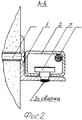
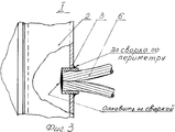
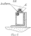
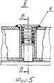
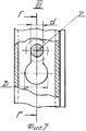
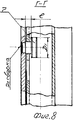
Изобретение поясняется чертежами, где на фиг.1 показан общий вид защитного устройства; съемная рамка вставлена в опорную рамку на стопорящие элементы и заблокирована на них запирающим устройством, проем закрыт; на фиг.2 - разрез А-А на фиг.1; на фиг.3 - место I на фиг.1; на фиг.4 - разрез Б-Б на фиг.1; на фиг.5 - место II на фиг.1; на фиг.6 - разрез В-В на фиг.5; на фиг.7 - место III на фиг.1; на фиг.8 - разрез Г-Г на фиг.7.The invention is illustrated by drawings, where figure 1 shows a General view of a protective device; a removable frame is inserted into the support frame on the locking elements and locked on them by a locking device, the opening is closed; figure 2 is a section aa in figure 1; figure 3 - place I in figure 1; figure 4 is a section bB in figure 1; figure 5 - place II in figure 1; figure 6 - section bb in figure 5; in Fig.7 - place III in Fig.1; in Fig.8 is a section GG in Fig.7.
Защитное устройство содержит опорную рамку 1, выполненную из стального уголкового профиля с жестко закрепленными стопорящими элементами 7 к боковым полкам в плоскости оконной рамы (фиг.2), и съемную рамку 2, выполненную из стальной трубы прямоугольного сечения с жестко закрепленным к внутреннему контуру ее ограждающим полотном 6, выполненным из троса посредством электросварки, при этом концы тросов ограждающего полотна 6 предварительно попарно спрессовываются стяжками 3 и оплавляются посредством электросварки (фиг.3), а крайние тросы ограждающего полотна 6 посередине каждой ячейки спрессовываются втулкой 5 (фиг.4). В съемной рамке 2 выполнены ![]()
![]()
Защитное устройство работает следующим образом. Для закрывания проема необходимо: вставить до упора съемную рамку 2 в жестко закрепленную внутри оконного проема крепежными элементами 11 опорную рамку 1, при этом стопорящие элементы 7, жестко закрепленные на опорной рамке 1 стопорящими буртиками диаметром D1 (фиг.8), входят во внутрь съемной рамки 2 через отверстия D (фиг.7). Взявшись за ограждающее полотно 6, приложить некоторое усилие и сдвинуть съемную рамку 2 вниз до упора с нижней полкой опорной рамки 1, преодолевая упругую силу пружин сжатия 8. В процессе перемещения съемной рамки 2 вниз происходит одновременное ее стопорение всеми стопорящими элементами 7 в плоскости перпендикулярной плоскости оконной рамы, поскольку стопорящие элементы 7 стержнями диаметром d входят в пазы ![]()
![]()
Для открывания проема необходимо открыть запирающее устройство. Под воздействием упругих сил пружин сжатия 8 происходит смещение съемной рамки 2 до упора в верхнюю полку опорной рамки 1, при этом стопорящие буртики D1 стопорящих элементов 7 выходят в соосность с отверстиями D в съемной рамке 2. Рамка съемная 2 вынимается из опорной рамки 1. Оконный проем открыт.To open the opening, you must open the locking device. Under the influence of the elastic forces of
Claims (1)
Priority Applications (1)
| Application Number | Priority Date | Filing Date | Title |
|---|---|---|---|
| RU2007102101/03A RU2349726C2 (en) | 2007-01-19 | 2007-01-19 | Protection device |
Applications Claiming Priority (1)
| Application Number | Priority Date | Filing Date | Title |
|---|---|---|---|
| RU2007102101/03A RU2349726C2 (en) | 2007-01-19 | 2007-01-19 | Protection device |
Publications (2)
| Publication Number | Publication Date |
|---|---|
| RU2007102101A RU2007102101A (en) | 2008-07-27 |
| RU2349726C2 true RU2349726C2 (en) | 2009-03-20 |
Family
ID=39810548
Family Applications (1)
| Application Number | Title | Priority Date | Filing Date |
|---|---|---|---|
| RU2007102101/03A RU2349726C2 (en) | 2007-01-19 | 2007-01-19 | Protection device |
Country Status (1)
| Country | Link |
|---|---|
| RU (1) | RU2349726C2 (en) |
Cited By (1)
| Publication number | Priority date | Publication date | Assignee | Title |
|---|---|---|---|---|
| RU2685738C1 (en) * | 2018-09-13 | 2019-04-23 | Дениз Кушаслан | Window safety system for children |
Families Citing this family (1)
| Publication number | Priority date | Publication date | Assignee | Title |
|---|---|---|---|---|
| CN103437651A (en) * | 2013-08-28 | 2013-12-11 | 张家港固耐特围栏系统有限公司 | Door body structure of side hung door |
-
2007
- 2007-01-19 RU RU2007102101/03A patent/RU2349726C2/en not_active IP Right Cessation
Cited By (1)
| Publication number | Priority date | Publication date | Assignee | Title |
|---|---|---|---|---|
| RU2685738C1 (en) * | 2018-09-13 | 2019-04-23 | Дениз Кушаслан | Window safety system for children |
Also Published As
| Publication number | Publication date |
|---|---|
| RU2007102101A (en) | 2008-07-27 |
Similar Documents
| Publication | Publication Date | Title |
|---|---|---|
| WO2015117227A1 (en) | Crossed ties for construction block assembly | |
| EP2872719A1 (en) | Insulation and strength reinforcement structure for sliding window | |
| KR20100102182A (en) | Profile for the facade of a multi-storey building and a multi-storey building with such a facade | |
| KR101547911B1 (en) | Insulated stainless steel door frame | |
| RU2349726C2 (en) | Protection device | |
| DE2439034A1 (en) | AGAINST HEAT RESISTANT GLAZING | |
| DE202009002800U1 (en) | Fire-resistant glazing | |
| DE102017113995A1 (en) | Laser protection device for shielding at least one laser light source with flat, flexible wall elements | |
| DK2910699T3 (en) | Edge Profile Element Interior | |
| DE3739020A1 (en) | Fire doors which are glazed and/or provided with panelling | |
| KR100828711B1 (en) | Multi Break Structure of Double Window Frame for Balcony | |
| KR102303438B1 (en) | Noncombustible exterior panel for exterior wall finish and method of construction thereof | |
| KR100935160B1 (en) | Insulated double windows having curtain assembly and safety bar | |
| KR20170004415U (en) | Self-assembly structure for glass greenhouse | |
| KR101045097B1 (en) | Safety working platform for a high place | |
| EP1972739A2 (en) | Extendable safety guardrail | |
| CN211312926U (en) | Connecting section bar and laser room wall | |
| CN211369607U (en) | Building hole faces limit protector | |
| ITRA950004A1 (en) | MULTIFUNCTIONAL SAFETY SHUTTERS FOR BUILDING AND OTHER APPLICATIONS | |
| RU2186186C2 (en) | Safety device | |
| CN210947167U (en) | Super high-rise SRC component building structure | |
| JP6999412B2 (en) | Construction method of outer wall panel Construction method of structure and outer wall | |
| CN106013534A (en) | Combined large-span curtain wall system | |
| KR20110100818A (en) | Elevator door | |
| CN204983608U (en) | Hanging flower basket is used in installation |
Legal Events
| Date | Code | Title | Description |
|---|---|---|---|
| MM4A | The patent is invalid due to non-payment of fees |
Effective date: 20160120 |