RU2345233C2 - Sealing turbojet engine by plate double-action gaskets for air intake to cabin - Google Patents
Sealing turbojet engine by plate double-action gaskets for air intake to cabin Download PDFInfo
- Publication number
- RU2345233C2 RU2345233C2 RU2004127898/06A RU2004127898A RU2345233C2 RU 2345233 C2 RU2345233 C2 RU 2345233C2 RU 2004127898/06 A RU2004127898/06 A RU 2004127898/06A RU 2004127898 A RU2004127898 A RU 2004127898A RU 2345233 C2 RU2345233 C2 RU 2345233C2
- Authority
- RU
- Russia
- Prior art keywords
- gasket
- flange
- protrusion
- ring
- gaskets
- Prior art date
Links
Images


Classifications
-
- F—MECHANICAL ENGINEERING; LIGHTING; HEATING; WEAPONS; BLASTING
- F02—COMBUSTION ENGINES; HOT-GAS OR COMBUSTION-PRODUCT ENGINE PLANTS
- F02K—JET-PROPULSION PLANTS
- F02K1/00—Plants characterised by the form or arrangement of the jet pipe or nozzle; Jet pipes or nozzles peculiar thereto
- F02K1/78—Other construction of jet pipes
- F02K1/80—Couplings or connections
-
- F—MECHANICAL ENGINEERING; LIGHTING; HEATING; WEAPONS; BLASTING
- F02—COMBUSTION ENGINES; HOT-GAS OR COMBUSTION-PRODUCT ENGINE PLANTS
- F02C—GAS-TURBINE PLANTS; AIR INTAKES FOR JET-PROPULSION PLANTS; CONTROLLING FUEL SUPPLY IN AIR-BREATHING JET-PROPULSION PLANTS
- F02C7/00—Features, components parts, details or accessories, not provided for in, or of interest apart form groups F02C1/00 - F02C6/00; Air intakes for jet-propulsion plants
- F02C7/28—Arrangement of seals
-
- F—MECHANICAL ENGINEERING; LIGHTING; HEATING; WEAPONS; BLASTING
- F01—MACHINES OR ENGINES IN GENERAL; ENGINE PLANTS IN GENERAL; STEAM ENGINES
- F01D—NON-POSITIVE DISPLACEMENT MACHINES OR ENGINES, e.g. STEAM TURBINES
- F01D11/00—Preventing or minimising internal leakage of working-fluid, e.g. between stages
- F01D11/005—Sealing means between non relatively rotating elements
-
- F—MECHANICAL ENGINEERING; LIGHTING; HEATING; WEAPONS; BLASTING
- F01—MACHINES OR ENGINES IN GENERAL; ENGINE PLANTS IN GENERAL; STEAM ENGINES
- F01D—NON-POSITIVE DISPLACEMENT MACHINES OR ENGINES, e.g. STEAM TURBINES
- F01D25/00—Component parts, details, or accessories, not provided for in, or of interest apart from, other groups
- F01D25/24—Casings; Casing parts, e.g. diaphragms, casing fastenings
- F01D25/246—Fastening of diaphragms or stator-rings
-
- F—MECHANICAL ENGINEERING; LIGHTING; HEATING; WEAPONS; BLASTING
- F02—COMBUSTION ENGINES; HOT-GAS OR COMBUSTION-PRODUCT ENGINE PLANTS
- F02K—JET-PROPULSION PLANTS
- F02K1/00—Plants characterised by the form or arrangement of the jet pipe or nozzle; Jet pipes or nozzles peculiar thereto
-
- F—MECHANICAL ENGINEERING; LIGHTING; HEATING; WEAPONS; BLASTING
- F16—ENGINEERING ELEMENTS AND UNITS; GENERAL MEASURES FOR PRODUCING AND MAINTAINING EFFECTIVE FUNCTIONING OF MACHINES OR INSTALLATIONS; THERMAL INSULATION IN GENERAL
- F16J—PISTONS; CYLINDERS; SEALINGS
- F16J15/00—Sealings
- F16J15/02—Sealings between relatively-stationary surfaces
- F16J15/06—Sealings between relatively-stationary surfaces with solid packing compressed between sealing surfaces
- F16J15/08—Sealings between relatively-stationary surfaces with solid packing compressed between sealing surfaces with exclusively metal packing
- F16J15/0887—Sealings between relatively-stationary surfaces with solid packing compressed between sealing surfaces with exclusively metal packing the sealing effect being obtained by elastic deformation of the packing
-
- F—MECHANICAL ENGINEERING; LIGHTING; HEATING; WEAPONS; BLASTING
- F05—INDEXING SCHEMES RELATING TO ENGINES OR PUMPS IN VARIOUS SUBCLASSES OF CLASSES F01-F04
- F05D—INDEXING SCHEME FOR ASPECTS RELATING TO NON-POSITIVE-DISPLACEMENT MACHINES OR ENGINES, GAS-TURBINES OR JET-PROPULSION PLANTS
- F05D2240/00—Components
- F05D2240/10—Stators
- F05D2240/11—Shroud seal segments
-
- F—MECHANICAL ENGINEERING; LIGHTING; HEATING; WEAPONS; BLASTING
- F05—INDEXING SCHEMES RELATING TO ENGINES OR PUMPS IN VARIOUS SUBCLASSES OF CLASSES F01-F04
- F05D—INDEXING SCHEME FOR ASPECTS RELATING TO NON-POSITIVE-DISPLACEMENT MACHINES OR ENGINES, GAS-TURBINES OR JET-PROPULSION PLANTS
- F05D2240/00—Components
- F05D2240/10—Stators
- F05D2240/12—Fluid guiding means, e.g. vanes
Abstract
Description
Настоящее изобретение относится к турбореактивному двигателю, содержащему от передней части к задней части, определяемых по направлению циркуляции первичного потока, компрессор высокого давления, решетку диффузора и камеру сгорания, при этом компрессор высокого давления содержит наружное кольцо, ограничивающее в радиальном направлении контур первичного потока и сопряженное с кольцевой конструкцией, выполненной радиально в наружном направлении, решетка диффузора содержит в осевом продолжении указанного наружного кольца компрессора наружный картер, сопряженный с конической опорной конструкцией, направленной в сторону задней части и ограничивающей спереди дно указанной камеры сгорания, при этом опорная конструкция сопрягается с наружным кольцом картера, выполненным в переднем направлении и закрепленным на указанной кольцевой конструкции при помощи крепежных средств, а опорная конструкция, наружное кольцо картера и кольцевая конструкция формируют полость вокруг указанной решетки диффузора, причем в опорной конструкции выполнены воздухозаборные отверстия для соединения дна камеры с указанной полостью, наружное кольцо картера содержит воздухозаборники, и между кольцевой конструкцией и наружным картером решетки диффузора выполнены средства уплотнения для изолирования указанной полости от контура первичного потока.The present invention relates to a turbojet engine containing from the front to the rear, determined in the direction of circulation of the primary stream, a high pressure compressor, a diffuser grill and a combustion chamber, wherein the high pressure compressor comprises an outer ring defining in the radial direction the primary flow circuit and mating with an annular structure, made radially in the outer direction, the diffuser grill contains in the axial continuation of the specified outer ring a compressor an external crankcase coupled to a conical supporting structure directed toward the rear and bounding the front of the bottom of said combustion chamber, the supporting structure being mated to the outer ring of the crankcase made in the front direction and secured to said ring structure by means of fixing means, and the supporting structure , the outer ring of the crankcase and the ring structure form a cavity around the specified diffuser grill, and in the supporting structure there are air inlet openings for connecting the bottom of the chamber with the specified cavity, the outer ring of the crankcase contains air intakes, and sealing means are made between the ring structure and the outer case of the diffuser grill to isolate the cavity from the primary flow circuit.
Забор воздуха, необходимого для кабины самолета, оборудованного, по меньшей мере, одним турбореактивным двигателем, осуществляют со дна камеры сгорания в зоне, где он наименее всего сказывается на общей производительности двигателя. Забор воздуха проводится через отверстия опорной конструкции, что позволяет легко устанавливать воздухозаборники. Такая конструкция требует обеспечения относительной герметичности между контуром компрессора высокого давления и полостью, расположенной над решеткой диффузора.The intake of air necessary for the cockpit of an aircraft equipped with at least one turbojet engine is carried out from the bottom of the combustion chamber in the area where it has the least effect on the overall engine performance. Air intake is carried out through the holes of the supporting structure, which makes it easy to install air intakes. This design requires ensuring relative tightness between the high pressure compressor circuit and the cavity located above the diffuser grill.
Такую герметичность достаточно сложно обеспечить по причине относительных смещений между решеткой диффузора и наружным кольцом компрессора, которые могут составлять значение порядка 1,5 мм в осевом направлении и практически значение такого же порядка в радиальном направлении и которые вызваны термическими и механическими напряжениями различных деталей, расположенных в окружающем пространстве и подвергающихся воздействию высокого давления, которое может достигать 30 бар, и высокой температуры, которая может достигать 650°С.It is quite difficult to ensure such a tightness due to relative displacements between the diffuser grill and the outer ring of the compressor, which can be of the order of 1.5 mm in the axial direction and practically the same value in the radial direction and which are caused by thermal and mechanical stresses of various parts located in the environment and exposed to high pressure, which can reach 30 bar, and high temperature, which can reach 650 ° C.
Современная технология, применяемая для обеспечения уплотнения между компрессором и наружным картером решетки, состоит в использовании пластинчатой прокладки и контрпрокладки, находящихся под действием давления пружины. Такая технология действительно обеспечивает достаточно свободное перемещение между двумя деталями.Modern technology used to provide a seal between the compressor and the outer grill housing consists in using a plate gasket and a counter gasket, which are under the influence of spring pressure. This technology really provides enough free movement between the two parts.
Известное техническое решение показано на фиг.1, на которой изображена последняя ступень компрессора высокого давления 1 турбореактивного двигателя, содержащего, начиная от передней части в сторону задней части по направлению первичного потока F1, колесо неподвижных лопаток 2, выполненных радиально во внутреннюю сторону, начиная от наружного картера 3, далее колесо подвижных лопаток 4, установленных по периферии рабочего колеса 5 компрессора в направлении наружной стороны вплоть до наружного кольца 6 компрессора, радиально ограничивающего вместе с наружным картером 3 контур первичного потока, при этом наружное кольцо 6 сопрягается с кольцевой конструкцией 7, имеющей сечение V-образной формы в плоскости, содержащей ось турбореактивного двигателя, и направленной радиально наружу, будучи одновременно закрепленной на наружном картере двигателя при помощи болтового соединения.The known technical solution is shown in figure 1, which shows the last stage of the high-
На выходе компрессора 1 установлена решетка 10 диффузора, на которую от компрессора 1 подается сжатый воздух, направляемый в камеру сгорания 11. В осевом продолжении наружного кольца 6 компрессора 1 решетка 10 содержит наружный картер 12, сопрягающийся с конической опорной конструкцией 13, направленной в сторону задней части турбореактивного двигателя, при этом указанная опорная конструкция 13 определяет переднюю стенку дна камеры сгорания 11 и сопрягается в своей радиально наружной зоне с наружным кольцом 14 картера, которое ориентировано в сторону передней части и содержит передний фланец 15, предназначенный для крепления при помощи болтового соединения узла, образованного камерой сгорания и диффузором, к радиально наружному фланцу 16 кольцевой конструкции 7.At the outlet of the
Таким образом окружающая решетку 10 диффузора полость ограничена в осевом направлении кольцевой конструкцией 7 и опорной конструкцией 13, радиально снаружи наружным кольцом 14 картера и радиально внутри задним участком 6а наружного кольца 6 компрессора и передним участком 12а наружного картера 12, при этом указанные два участка отделены друг от друга промежуточным пространством 21.Thus, the cavity surrounding the
Опорная конструкция 13 содержит отверстия 22 для забора воздуха на дне камеры, а наружное кольцо 14 картера содержит воздухозаборники 23 для подачи воздуха с целью вентиляции кабины самолета и охлаждения других элементов турбореактивного двигателя.The supporting
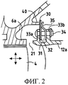
Как показано на фиг.2, уплотнение между контуром компрессора и полостью 20 обеспечивается сегментной пластинчатой прокладкой 30 и подложенными под ее пластины контрпрокладками 31, установленной по контуру переднего участка 12а наружного картера 12 решетки диффузора. Для этой цели указанный передний участок 12а содержит по своему контуру кольцевую выточку 32, ограниченную двумя фланцами, передним 33а и задним 33b, которые содержат сквозные отверстия для клепочного соединения 34.As shown in FIG. 2, the seal between the compressor circuit and the
Пластины 30 и контрпрокладки 31 удерживаются в опорном положении на задней стороне переднего фланца 33а при помощи пружин 32 и закреплены заклепками 34. Пружины 35 также закреплены при помощи заклепок 34. Радиально внутренний участок кольцевой конструкции содержит кольцевой выступ 40, выполненный в осевом направлении в сторону полости 20, при этом его конец находится над передним фланцем 33а при отсутствии осевого перемещения между наружным кольцом 6 компрессора 1 и наружным картером 12 диффузора, как показано на фиг.2.The
Пружины 35 давят на прокладки в кольцевой зоне, разделяющей выступ 40 и передний фланец 33а. С другой стороны, давление воздуха в полости 20 несколько превышает давление в контуре на уровне промежуточного пространства 21.Springs 35 press on the gaskets in the annular zone separating the
Опорные поверхности прокладок 30 со стороны выступа 40 и со стороны переднего фланца 33а содержат выпуклости. Совместные усилия от пружин 35 и разности давления, действующие на обе стороны прокладок 30, прижимают пластины 30, выполненные плоскими, к выпуклым поверхностям в показанном на фиг.2 положении, что и обеспечивает уплотнение.The supporting surfaces of the
В некоторых фазах полета в опорном положении между пластинами 30 и выступом 40 остаются зазоры, в частности, когда выступ 40 перемещается над кольцевой выточкой 32, как показано на фиг.4 и 5. Между двумя последовательно расположенными пружинами пластины 30 отходят от выступа, и появлению зазора может помешать только разность давления между двумя сторонами, которая является довольно незначительной. В этом случае происходит утечка через зазор 41 между пластинами и концом выступа 40.In some phases of the flight, gaps remain between the
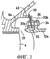
Когда же решетка 10 диффузора удаляется от компрессора 1, как показано на фиг.3, усилие за счет разности давления и действия пружин 35 обеспечивает нормальное уплотнение благодаря деформации пластин 30.When the
Двойными стрелками на фиг.2 показаны относительные перемещения в осевом и радиальном направлениях между задним концом наружного кольца 6 компрессора и передним концом наружного картера 12 решетки 10 диффузора.The double arrows in FIG. 2 show the relative axial and radial movements between the rear end of the
Необходимо также отметить, что конструкция уплотнения на наружном картере 12 обеспечивает монтаж узла из камеры сгорания и диффузора на компрессоре путем относительного осевого перемещения указанного узла по отношению к компрессору и затем с помощью болтового соединения наружных фланцев 15 и 16.It should also be noted that the design of the seal on the
Задачей настоящего изобретения является обеспечение полной герметичности между полостью и контуром первичного потока, независимо от изменений размеров промежуточного пространства и от колебаний разности давления между двумя сторонами уплотненной зоны.The objective of the present invention is to ensure complete tightness between the cavity and the primary flow loop, regardless of changes in the size of the intermediate space and from fluctuations in the pressure difference between the two sides of the sealed zone.
Поставленная задача решается тем, что в турбореактивном двигателе, содержащем в направлении от передней части к задней части, определяемых по направлению циркуляции первичного потока, компрессор высокого давления, решетку диффузора и камеру сгорания, при этом компрессор высокого давления содержит наружное кольцо, ограничивающее в радиальном направлении контур первичного потока и сопряженное с кольцевой конструкцией, выполненной радиально в наружном направлении, при этом решетка диффузора содержит в осевом продолжении наружного кольца компрессора наружный картер, сопряженный с конической опорной конструкцией, направленной в сторону задней части и ограничивающей спереди дно камеры сгорания, а коническая опорная конструкция сопрягается с наружным кольцом картера, выполненным в переднем направлении и закрепленным на кольцевой конструкции при помощи крепежных средств, причем коническая опорная конструкция, наружное кольцо картера и кольцевая конструкция формируют полость вокруг решетки диффузора, и в опорной конструкции выполнены воздухозаборные отверстия для соединения дна камеры с полостью, при этом наружное кольцо картера содержит воздухозаборники, а между кольцевой конструкцией и наружным картером решетки диффузора предусмотрены средства уплотнения для изолирования полости от контура первичного потока, средства уплотнения содержат первую и вторую прокладки типа сегментных пластинчатых прокладок с подложенными под них контрпрокладками, на которые действуют усилия пружин, при этом указанную первую прокладку устанавливают в первый паз, выполненный вокруг передней части наружного картера решетки диффузора, причем пластины первой прокладки опираются на задний конец первого выступа, выполненного заодно с кольцевой конструкцией, а указанную вторую прокладку устанавливают во второй паз, выполненный под указанной кольцевой конструкцией, при этом пластины этой второй прокладки опираются на передний конец второго выступа, выполненного заодно с указанной кольцевой конструкцией, и на передний конец третьего выступа, выполненного заодно с указанной передней частью наружного картера.The problem is solved in that in a turbojet engine containing in the direction from the front to the rear, determined in the direction of circulation of the primary stream, a high pressure compressor, a diffuser grill and a combustion chamber, while the high pressure compressor contains an outer ring, limiting in the radial direction the primary flow circuit and associated with the ring structure, made radially in the outer direction, while the diffuser grille contains in the axial continuation of the outer ring Compressor outer casing coupled with a conical supporting structure directed towards the rear and bounding the bottom of the combustion chamber in front, and the conical supporting structure mating with the outer ring of the crankcase made in the front direction and secured to the ring structure using fastening means, the conical supporting the structure, the crankcase outer ring and the ring structure form a cavity around the diffuser grill, and air intake openings for uniting the bottom of the chamber with the cavity, while the outer ring of the crankcase contains air intakes, and between the ring structure and the outer case of the diffuser grill, sealing means are provided to isolate the cavity from the primary flow circuit, sealing means comprise first and second gaskets, such as segmented plate gaskets with counter gaskets underneath , which are exerted by the efforts of the springs, while the specified first gasket is installed in the first groove made around the front of the outer casing diffuser gratings, the plates of the first gasket resting on the rear end of the first protrusion made integral with the ring structure, and the specified second gasket installed in the second groove made under the specified ring structure, while the plates of this second gasket rest on the front end of the second protrusion made at the same time with the indicated ring structure, and at the front end of the third protrusion made integrally with the specified front part of the outer casing.
Установка второй прокладки обратного действия обеспечивает реагирование на все изменения направления разности давления, а также способствует усилению всей системы, дополнительно затрудняя переход при очень слабых градиентах благодаря наличию шлюза между двумя прокладками.The installation of a second reverse-action gasket provides a response to all changes in the direction of the pressure difference, and also enhances the entire system, further complicating the transition at very weak gradients due to the presence of a gateway between the two gaskets.
Первый паз ограничен передним фланцем и задним фланцем, при этом первая прокладка и первые пружины удерживаются на месте заклепками, закрепленными на указанных фланцах, а третий выступ выполнен на передней стороне указанного переднего фланца.The first groove is bounded by the front flange and the rear flange, while the first gasket and the first springs are held in place by rivets mounted on these flanges, and the third protrusion is made on the front side of the specified front flange.
Кольцевая конструкция содержит радиально внутреннюю часть, направленную в сторону выхода, и второй паз ограничен указанной частью и третьим фланцем, находящимся над передним фланцем, при этом первый выступ направлен в заднюю сторону, начиная от радиально внутреннего конца указанного третьего фланца, при этом указанный конец дополнительно содержит второй выступ, направленный в переднюю сторону, на который опирается вторая прокладка. Вторые пружины закреплены на лапках, выполненных на кольцевой конструкции, независимо от крепления штифтами пластин и контрпрокладок второй прокладки во втором пазу.The ring structure contains a radially inner part directed towards the exit side, and the second groove is bounded by the indicated part and the third flange located above the front flange, the first protrusion directed to the rear side, starting from the radially inner end of the specified third flange, while this end is additionally contains a second protrusion directed to the front side, on which the second gasket rests. The second springs are mounted on tabs made on an annular structure, irrespective of the fastening by the pins of the plates and the counter-gaskets of the second gasket in the second groove.
Другие преимущества и отличительные признаки настоящего изобретения будут более очевидны из нижеследующего описания, представленного в качестве примера, со ссылками на прилагаемые чертежи, в числе которых:Other advantages and features of the present invention will be more apparent from the following description, presented as an example, with reference to the accompanying drawings, including:
фиг.1-5 представляют технические решения из предшествующего уровня техники.1-5 represent technical solutions from the prior art.
Фиг.1 представляет изображение в полуразрезе по плоскости, содержащей ось турбореактивного двигателя, задней части компрессора и диффузора, иллюстрирующее вариант выполнения полости, сообщающейся с дном камеры, на котором происходит отбор воздуха для кабины самолета, и вариант установки известной из предшествующего уровня техники уплотнительной прокладки между указанной полостью и контуром первичного потока.Figure 1 is an image in half section along a plane containing the axis of the turbojet engine, the rear of the compressor and diffuser, illustrating an embodiment of a cavity communicating with the bottom of the chamber on which air is taken for the airplane cabin, and an installation option of a gasket known from the prior art between the specified cavity and the primary flow circuit.
Фиг.2 изображает в увеличенном масштабе конструкцию уплотнительной прокладки из предшествующего уровня техники.Figure 2 depicts on an enlarged scale the design of the gasket from the prior art.
Фиг.3 иллюстрирует деформацию прокладки в случае увеличения промежуточного пространства между наружным кольцом компрессора и наружным картером решетки диффузора.Figure 3 illustrates the deformation of the gasket in case of an increase in the intermediate space between the outer ring of the compressor and the outer case of the diffuser grill.
Фиг.4 иллюстрирует деформацию этой же прокладки в случае уменьшения этого промежуточного пространства.Figure 4 illustrates the deformation of the same gasket in case of reduction of this intermediate space.
Фиг.5 изображает в перспективе уплотнительную прокладку в случае уменьшения промежуточного пространства при появлении утечки через образовавшийся зазор.Figure 5 depicts a perspective gasket in the case of a decrease in the intermediate space when a leak appears through the resulting gap.
Фиг.6 изображает уплотнительную систему в соответствии с настоящим изобретением, предназначенную для изолирования воздухозаборной полости от контура первичного потока.6 depicts a sealing system in accordance with the present invention, designed to isolate the air intake cavity from the primary flow circuit.
Фиг.7 изображает способ крепления между корпусом компрессора и узлом «диффузор-камера сгорания».7 depicts a mounting method between a compressor housing and a diffuser-combustion chamber assembly.
Фиг.1-5, иллюстрирующие известные технические решения, были подробно описаны в преамбуле описания изобретения и не нуждаются в дополнительных разъяснениях.Figure 1-5, illustrating well-known technical solutions, have been described in detail in the preamble of the description of the invention and do not need further explanation.
На фиг.6 показана уплотнительная система в соответствии с настоящим изобретением, предназначенная для изолирования полости 20 от контура первичного потока F1. На данной фигуре различные элементы, ограничивающие полость 20, обозначены теми же позициями, что и идентичные им элементы на фиг.1-5.Figure 6 shows a sealing system in accordance with the present invention, designed to isolate the
Уплотнительная система содержит первую уплотнительную прокладку 50, установленную по периферии переднего участка 12а наружного картера 12 решетки 10 диффузора. При этом данная уплотнительная прокладка аналогична известной из предшествующего уровня техники прокладке, показанной на фиг.2, и вторая уплотнительная прокладка 60, расположенная перед первой прокладкой 50, выполнена также в виде пластинчатой прокладки и установлена на радиально внутренней части 7а кольцевой конструкции 7 компрессора.The sealing system comprises a first sealing
Для этого указанная часть 7а, расположенная практически параллельно опорной конструкции 13, содержит над передним фланцем 33а третий фланец 70, ориентированный радиально в сторону внутреннего объема, и его радиально внутренний конец содержит первый выступ 71, ориентированный в направлении выхода, и второй выступ 72, ориентированный в сторону входа.To this end, said
Пластины 30 первой прокладки 50 опираются на свободный конец первого выступа 71. Эти пластины удерживаются в пазу 32, отделяющем передний фланец 33а от заднего фланца 33b, при помощи заклепок 34 и опираются на заднюю сторону переднего фланца 33а и на свободный конец первого выступа 71 за счет действия пружин 35, которые также удерживаются заклепками 34 и опираются на переднюю сторону заднего фланца 33b.The
Вместе с частью 7а кольцевой конструкции третий фланец 70 ограничивает кольцевую выточку 73, выполняющую функцию паза 32. Установленные в третьем фланце 70 штифты удерживают радиально наружные зоны пластин 30 и контрпрокладки 31 второй уплотнительной прокладки 60.Together with
Перед третьим фланцем часть 7а содержит также лапки 74, обеспечивающие удержание вторых пружин 75 при помощи клепочного соединения, при этом указанные вторые пружины давят на контрпрокладки 31 и пластины 30 второй прокладки 60 таким образом, что эти пластины опираются с одной стороны на передний конец второго выступа 72 и на третий выступ 76, выполненный по периферии передней стороны переднего фланца 33а.In front of the third flange,
Каждая из двух описанных выше прокладок 50 и 60 действует так же, как и известная из предшествующего уровня техники прокладка, описанная со ссылками на фиг.1-5, но в противоположных направлениях.Each of the two
Для того чтобы помешать одной из прокладок занять положение, показанное на фиг.4 и 5, первый 71 и второй 72 выступы имеют такие размеры, при которых эти выступы всегда находятся над передним фланцем 33а, независимо от осевых относительных перемещений этих двух элементов во время работы. Таким образом, расстояние между концами первого выступа 71 и второго выступа 72 имеет значение, меньшее значения суммы толщины переднего фланца 33а и длины третьего фланца 76.In order to prevent one of the gaskets from taking the position shown in FIGS. 4 and 5, the first 71 and second 72 protrusions are dimensioned so that these protrusions are always above the
На фиг.7 показано положение первой прокладки 50 на узле, образованном диффузором и камерой сгорания, и положение второй прокладки на компрессоре перед монтажом этих двух деталей.Figure 7 shows the position of the
Эти две детали расположены в осевом направлении на расстоянии друг от друга таким образом, чтобы при их сближении в осевом направлении, показанном стрелками М, первая прокладка 50 опиралась на первый выступ 71, а вторая прокладка 60 опиралась на третий выступ 76. Когда фланец 16 кольцевой конструкции 7 и фланец 15 наружного кольца картера 14 находятся в положении взаимного контакта, их можно закрепить при помощи болтового соединения. Таким образом монтаж осуществляют вслепую.These two parts are axially spaced apart from each other so that when they approach each other in the axial direction shown by arrows M, the
Claims (4)
отличающийся тем, что средства уплотнения содержат первую (50) и вторую (60) прокладки типа сегментных пластинчатых прокладок с подложенными под них контрпрокладками, на которые действуют усилия пружин, при этом указанную первую прокладку (50) устанавливают в первый паз (32), выполненный вокруг передней части (12а) наружного картера (12) решетки диффузора, пластины первой прокладки опираются за счет действия первых пружин (35) на задний конец первого выступа (71), выполненного заодно с кольцевой конструкцией (7), а вторую прокладку (60) устанавливают во второй паз (73), выполненный под кольцевой конструкцией (7), причем пластины второй прокладки опираются за счет действия вторых пружин (75) на передний конец второго выступа (72), выполненного заодно с кольцевой конструкцией, и на передний конец третьего выступа (76), выполненного заодно с передней частью (12а) наружного картера.1. A turbojet engine containing in the direction from the front to the back, determined in the direction of circulation of the primary stream, a high pressure compressor (1), a diffuser grill (10) and a combustion chamber, wherein the high pressure compressor comprises an outer ring (6), the primary flow limiting in the radial direction and conjugated with the ring structure (7), made radially in the outer direction, while the diffuser grille contains in the axial continuation of the outer ring (6) of the compressor an outer cable a rotor (12), conjugated with a conical support structure (13) directed toward the rear and bounding the bottom of the combustion chamber in front, and the conical support structure mates with the outer ring of the crankcase (14), made in the front direction and mounted on the ring structure (7 ) using fasteners, moreover, the conical support structure, the outer crankcase ring and the ring structure form a cavity (20) around the diffuser grill (10), and air support holes (22) are made in the support structure (13) for connecting the bottom of the chamber with a cavity (20), while the outer ring of the crankcase contains air intakes (23), and between the ring structure (7) and the outer case (12) of the diffuser grill, sealing means are provided to isolate the cavity (20) from the primary flow circuit,
characterized in that the sealing means comprise first (50) and second (60) gaskets of the type of segmented plate gaskets with counter-gaskets placed under them, which are exerted by the efforts of the springs, while said first gasket (50) is installed in the first groove (32) made around the front part (12a) of the outer case (12) of the diffuser grill, the plates of the first gasket are supported by the action of the first springs (35) on the rear end of the first protrusion (71), which is integral with the ring structure (7), and the second gasket (60) set in a second groove (73) made under the annular structure (7), the plates of the second gasket being supported by the action of the second springs (75) on the front end of the second protrusion (72), integral with the ring structure, and on the front end of the third protrusion (76) ) made integrally with the front part (12a) of the external crankcase.
Applications Claiming Priority (2)
| Application Number | Priority Date | Filing Date | Title |
|---|---|---|---|
| FR0311020A FR2860039B1 (en) | 2003-09-19 | 2003-09-19 | REALIZATION OF THE SEAL IN A TURBOJET FOR THE COLLECTION OF DOUBLE-SIDED JOINTS |
| FR0311020 | 2003-09-19 |
Publications (2)
| Publication Number | Publication Date |
|---|---|
| RU2004127898A RU2004127898A (en) | 2006-02-27 |
| RU2345233C2 true RU2345233C2 (en) | 2009-01-27 |
Family
ID=34178923
Family Applications (1)
| Application Number | Title | Priority Date | Filing Date |
|---|---|---|---|
| RU2004127898/06A RU2345233C2 (en) | 2003-09-19 | 2004-09-17 | Sealing turbojet engine by plate double-action gaskets for air intake to cabin |
Country Status (9)
| Country | Link |
|---|---|
| US (1) | US7040098B2 (en) |
| EP (1) | EP1517005B1 (en) |
| JP (1) | JP4047843B2 (en) |
| KR (1) | KR101146402B1 (en) |
| CN (1) | CN100427736C (en) |
| DE (1) | DE602004004023T2 (en) |
| FR (1) | FR2860039B1 (en) |
| RU (1) | RU2345233C2 (en) |
| UA (1) | UA84267C2 (en) |
Cited By (3)
| Publication number | Priority date | Publication date | Assignee | Title |
|---|---|---|---|---|
| RU2525384C2 (en) * | 2012-11-07 | 2014-08-10 | Российская Федерация, от имени которой выступает Министерство промышленности и торговли Российской Федерации (Минпромторг России) | Gas turbine engine compressor stator |
| RU2574124C2 (en) * | 2011-02-28 | 2016-02-10 | Альстом Текнолоджи Лтд | Turbine equipped with sealing device between cartridge of guide vanes and casing |
| US9422822B2 (en) | 2011-02-28 | 2016-08-23 | Alstom Technology Ltd | Turbine comprising a sealing device between the stator blade carrier and the housing |
Families Citing this family (25)
| Publication number | Priority date | Publication date | Assignee | Title |
|---|---|---|---|---|
| FR2860041B1 (en) * | 2003-09-22 | 2005-11-25 | Snecma Moteurs | REALIZING THE SEALING IN A TURBOJET FOR THE DOUBLE BALL TUBE COLLECTION |
| KR101065846B1 (en) | 2005-11-17 | 2011-09-19 | 한국전자통신연구원 | Method and Apparatus for Transmitting by Using Transmit Diversity at DFT Spread OFDMA |
| US7775048B2 (en) * | 2006-06-30 | 2010-08-17 | General Electric Company | Seal assembly |
| US7793507B2 (en) * | 2006-09-07 | 2010-09-14 | General Electric Company | Expansion joint for gas turbines |
| FR2913051B1 (en) * | 2007-02-28 | 2011-06-10 | Snecma | TURBINE STAGE IN A TURBOMACHINE |
| US7744092B2 (en) * | 2007-04-30 | 2010-06-29 | General Electric Company | Methods and apparatus to facilitate sealing in rotary machines |
| US7900461B2 (en) * | 2007-05-31 | 2011-03-08 | Rolls-Royce Corporation | Combustor liner support and seal assembly |
| US7909300B2 (en) * | 2007-10-18 | 2011-03-22 | General Electric Company | Combustor bracket assembly |
| US8534076B2 (en) * | 2009-06-09 | 2013-09-17 | Honeywell Internationl Inc. | Combustor-turbine seal interface for gas turbine engine |
| US8388307B2 (en) * | 2009-07-21 | 2013-03-05 | Honeywell International Inc. | Turbine nozzle assembly including radially-compliant spring member for gas turbine engine |
| GB201105103D0 (en) * | 2011-03-28 | 2011-05-11 | Rolls Royce Plc | Securing system |
| US8888445B2 (en) * | 2011-08-19 | 2014-11-18 | General Electric Company | Turbomachine seal assembly |
| US9200565B2 (en) * | 2011-12-05 | 2015-12-01 | Siemens Energy, Inc. | Full hoop casing for midframe of industrial gas turbine engine |
| FR2989426B1 (en) * | 2012-04-11 | 2014-03-28 | Snecma | TURBOMACHINE, SUCH AS A TURBOJET OR AIRCRAFT TURBOPROPULSER |
| US10190441B2 (en) * | 2013-03-14 | 2019-01-29 | United Technologies Corporation | Triple flange arrangement for a gas turbine engine |
| US9850771B2 (en) * | 2014-02-07 | 2017-12-26 | United Technologies Corporation | Gas turbine engine sealing arrangement |
| KR101560730B1 (en) * | 2014-05-28 | 2015-10-19 | 한국전력공사 | Sealing apparatus for diffuser of gas turbine |
| US9816387B2 (en) | 2014-09-09 | 2017-11-14 | United Technologies Corporation | Attachment faces for clamped turbine stator of a gas turbine engine |
| US10301957B2 (en) * | 2014-12-17 | 2019-05-28 | United Technologies Corporation | Pinned seal |
| ES2684387T3 (en) | 2015-05-08 | 2018-10-02 | MTU Aero Engines AG | Turbomachine with a shutter |
| ES2861200T3 (en) * | 2015-12-15 | 2021-10-06 | MTU Aero Engines AG | Turbomachinery Component Connection |
| US10830103B2 (en) * | 2017-07-05 | 2020-11-10 | General Electric Company | Expansion joint and methods of assembling the same |
| FR3095830B1 (en) * | 2019-05-10 | 2021-05-07 | Safran Aircraft Engines | TURBOMACHINE MODULE EQUIPPED WITH A SEALING FLAP HOLDING DEVICE |
| CN110374698B (en) * | 2019-07-15 | 2022-02-22 | 中国航发沈阳发动机研究所 | Bearing ring assembly and double-layer casing structure with same |
| US11448078B2 (en) * | 2020-04-23 | 2022-09-20 | Raytheon Technologies Corporation | Spring loaded airfoil vane |
Family Cites Families (19)
| Publication number | Priority date | Publication date | Assignee | Title |
|---|---|---|---|---|
| GB1605297A (en) * | 1977-05-05 | 1988-06-08 | Rolls Royce | Nozzle guide vane structure for a gas turbine engine |
| US5118120A (en) * | 1989-07-10 | 1992-06-02 | General Electric Company | Leaf seals |
| JPH0749832B2 (en) * | 1989-07-10 | 1995-05-31 | ゼネラル・エレクトリック・カンパニイ | Turbo engine |
| US5291732A (en) * | 1993-02-08 | 1994-03-08 | General Electric Company | Combustor liner support assembly |
| US5797723A (en) * | 1996-11-13 | 1998-08-25 | General Electric Company | Turbine flowpath seal |
| US5848874A (en) * | 1997-05-13 | 1998-12-15 | United Technologies Corporation | Gas turbine stator vane assembly |
| FR2786222B1 (en) * | 1998-11-19 | 2000-12-29 | Snecma | LAMELLE SEALING DEVICE |
| US6164656A (en) * | 1999-01-29 | 2000-12-26 | General Electric Company | Turbine nozzle interface seal and methods |
| US6347508B1 (en) * | 2000-03-22 | 2002-02-19 | Allison Advanced Development Company | Combustor liner support and seal assembly |
| FR2825787B1 (en) * | 2001-06-06 | 2004-08-27 | Snecma Moteurs | FITTING OF CMC COMBUSTION CHAMBER OF TURBOMACHINE BY FLEXIBLE LINKS |
| FR2825781B1 (en) * | 2001-06-06 | 2004-02-06 | Snecma Moteurs | ELASTIC MOUNTING OF THIS COMBUSTION CMC OF TURBOMACHINE IN A METAL HOUSING |
| FR2825785B1 (en) * | 2001-06-06 | 2004-08-27 | Snecma Moteurs | TWO-PIECE TURBOMACHINE CMC COMBUSTION CHAMBER LINKAGE |
| US6464457B1 (en) * | 2001-06-21 | 2002-10-15 | General Electric Company | Turbine leaf seal mounting with headless pins |
| FR2829796B1 (en) * | 2001-09-20 | 2003-12-12 | Snecma Moteurs | DEVICE FOR HOLDING JOINTS OF PLATFORMS OF DISTRIBUTOR SECTORS OF TURBOMACHINE WITH SEALING BLADES |
| JP3840556B2 (en) * | 2002-08-22 | 2006-11-01 | 川崎重工業株式会社 | Combustor liner seal structure |
| US6895761B2 (en) * | 2002-12-20 | 2005-05-24 | General Electric Company | Mounting assembly for the aft end of a ceramic matrix composite liner in a gas turbine engine combustor |
| FR2859762B1 (en) * | 2003-09-11 | 2006-01-06 | Snecma Moteurs | REALIZATION OF SEALING FOR CABIN TAKEN BY SEGMENT SEAL |
| FR2860040B1 (en) * | 2003-09-19 | 2006-02-10 | Snecma Moteurs | REALIZING THE SEALING IN A TURBOJET FOR THE CABIN TAKEN BY A BRUSH SEAL |
| FR2860041B1 (en) | 2003-09-22 | 2005-11-25 | Snecma Moteurs | REALIZING THE SEALING IN A TURBOJET FOR THE DOUBLE BALL TUBE COLLECTION |
-
2003
- 2003-09-19 FR FR0311020A patent/FR2860039B1/en not_active Expired - Fee Related
-
2004
- 2004-08-30 US US10/928,279 patent/US7040098B2/en active Active
- 2004-09-07 KR KR1020040071426A patent/KR101146402B1/en active IP Right Grant
- 2004-09-09 JP JP2004261962A patent/JP4047843B2/en active Active
- 2004-09-15 CN CNB2004100791964A patent/CN100427736C/en active Active
- 2004-09-17 RU RU2004127898/06A patent/RU2345233C2/en active
- 2004-09-17 EP EP04292228A patent/EP1517005B1/en active Active
- 2004-09-17 DE DE602004004023T patent/DE602004004023T2/en active Active
- 2004-09-17 UA UA20040907579A patent/UA84267C2/en unknown
Cited By (3)
| Publication number | Priority date | Publication date | Assignee | Title |
|---|---|---|---|---|
| RU2574124C2 (en) * | 2011-02-28 | 2016-02-10 | Альстом Текнолоджи Лтд | Turbine equipped with sealing device between cartridge of guide vanes and casing |
| US9422822B2 (en) | 2011-02-28 | 2016-08-23 | Alstom Technology Ltd | Turbine comprising a sealing device between the stator blade carrier and the housing |
| RU2525384C2 (en) * | 2012-11-07 | 2014-08-10 | Российская Федерация, от имени которой выступает Министерство промышленности и торговли Российской Федерации (Минпромторг России) | Gas turbine engine compressor stator |
Also Published As
| Publication number | Publication date |
|---|---|
| CN1598271A (en) | 2005-03-23 |
| EP1517005B1 (en) | 2007-01-03 |
| FR2860039A1 (en) | 2005-03-25 |
| JP4047843B2 (en) | 2008-02-13 |
| US7040098B2 (en) | 2006-05-09 |
| CN100427736C (en) | 2008-10-22 |
| RU2004127898A (en) | 2006-02-27 |
| UA84267C2 (en) | 2008-10-10 |
| EP1517005A1 (en) | 2005-03-23 |
| KR20050028783A (en) | 2005-03-23 |
| FR2860039B1 (en) | 2005-11-25 |
| DE602004004023D1 (en) | 2007-02-15 |
| KR101146402B1 (en) | 2012-05-17 |
| DE602004004023T2 (en) | 2007-11-15 |
| JP2005090507A (en) | 2005-04-07 |
| US20050061005A1 (en) | 2005-03-24 |
Similar Documents
| Publication | Publication Date | Title |
|---|---|---|
| RU2345233C2 (en) | Sealing turbojet engine by plate double-action gaskets for air intake to cabin | |
| RU2450129C2 (en) | Interturbine case with cooling circuit and gas turbine engine therewith | |
| US8661828B2 (en) | Sealing between a combustion chamber and a turbine nozzle in a turbomachine | |
| KR101076834B1 (en) | Improved variable geometry assembly for turbochargers | |
| US5372476A (en) | Turbine nozzle support assembly | |
| CA2715227C (en) | Sealing for vane segments | |
| US8162605B2 (en) | Gas turbine engine case | |
| RU2636597C2 (en) | Turbomachine, such as aviation turbojet engine or turboprop engine | |
| RU2365777C2 (en) | Turbofan jet engine with auxiliary distributed support | |
| US9328926B2 (en) | Segmented combustion chamber head | |
| US7752851B2 (en) | Fastening a combustion chamber inside its casing | |
| US20050242522A1 (en) | Seal between the inner and outer casings of a turbojet section | |
| JP2002372241A (en) | Combustion chamber having system to fix combustion chamber and part wall | |
| RU2355894C2 (en) | Turbo-jet engine | |
| KR101120083B1 (en) | Provision of sealing for the cabin-air bleed cavity using a segment seal | |
| US11300000B2 (en) | Panel for tip clearance control | |
| US4730832A (en) | Sealed telescopic joint and method of assembly | |
| CN111712623B (en) | Outer shroud for the intermediate casing of a double flow turbine engine of an aircraft comprising improved air sealing and fire-resistant means | |
| US4635332A (en) | Sealed telescopic joint and method of assembly | |
| UA82060C2 (en) | Device for provision of tightness of turbo-jet engine | |
| US5054282A (en) | Drain assembly | |
| US5095617A (en) | Method for forming a drain assembly | |
| CN115013161A (en) | Turbine interstage supporting structure and gas turbine engine | |
| CN113518850B (en) | Mid-frame section of a gas turbine engine and corresponding method of adjusting radial rotor clearance | |
| US20230340926A1 (en) | Sealing assembly for a turbine ejection cone |
Legal Events
| Date | Code | Title | Description |
|---|---|---|---|
| PD4A | Correction of name of patent owner |