US10190441B2 - Triple flange arrangement for a gas turbine engine - Google Patents
Triple flange arrangement for a gas turbine engine Download PDFInfo
- Publication number
- US10190441B2 US10190441B2 US14/773,865 US201414773865A US10190441B2 US 10190441 B2 US10190441 B2 US 10190441B2 US 201414773865 A US201414773865 A US 201414773865A US 10190441 B2 US10190441 B2 US 10190441B2
- Authority
- US
- United States
- Prior art keywords
- flange
- aft
- case
- bearing
- recited
- Prior art date
- Legal status (The legal status is an assumption and is not a legal conclusion. Google has not performed a legal analysis and makes no representation as to the accuracy of the status listed.)
- Active, expires
Links
Images


Classifications
-
- F—MECHANICAL ENGINEERING; LIGHTING; HEATING; WEAPONS; BLASTING
- F01—MACHINES OR ENGINES IN GENERAL; ENGINE PLANTS IN GENERAL; STEAM ENGINES
- F01D—NON-POSITIVE DISPLACEMENT MACHINES OR ENGINES, e.g. STEAM TURBINES
- F01D25/00—Component parts, details, or accessories, not provided for in, or of interest apart from, other groups
- F01D25/28—Supporting or mounting arrangements, e.g. for turbine casing
-
- F—MECHANICAL ENGINEERING; LIGHTING; HEATING; WEAPONS; BLASTING
- F01—MACHINES OR ENGINES IN GENERAL; ENGINE PLANTS IN GENERAL; STEAM ENGINES
- F01D—NON-POSITIVE DISPLACEMENT MACHINES OR ENGINES, e.g. STEAM TURBINES
- F01D25/00—Component parts, details, or accessories, not provided for in, or of interest apart from, other groups
- F01D25/16—Arrangement of bearings; Supporting or mounting bearings in casings
- F01D25/162—Bearing supports
-
- F—MECHANICAL ENGINEERING; LIGHTING; HEATING; WEAPONS; BLASTING
- F01—MACHINES OR ENGINES IN GENERAL; ENGINE PLANTS IN GENERAL; STEAM ENGINES
- F01D—NON-POSITIVE DISPLACEMENT MACHINES OR ENGINES, e.g. STEAM TURBINES
- F01D25/00—Component parts, details, or accessories, not provided for in, or of interest apart from, other groups
- F01D25/30—Exhaust heads, chambers, or the like
-
- F—MECHANICAL ENGINEERING; LIGHTING; HEATING; WEAPONS; BLASTING
- F02—COMBUSTION ENGINES; HOT-GAS OR COMBUSTION-PRODUCT ENGINE PLANTS
- F02C—GAS-TURBINE PLANTS; AIR INTAKES FOR JET-PROPULSION PLANTS; CONTROLLING FUEL SUPPLY IN AIR-BREATHING JET-PROPULSION PLANTS
- F02C7/00—Features, components parts, details or accessories, not provided for in, or of interest apart form groups F02C1/00 - F02C6/00; Air intakes for jet-propulsion plants
- F02C7/20—Mounting or supporting of plant; Accommodating heat expansion or creep
-
- F—MECHANICAL ENGINEERING; LIGHTING; HEATING; WEAPONS; BLASTING
- F02—COMBUSTION ENGINES; HOT-GAS OR COMBUSTION-PRODUCT ENGINE PLANTS
- F02C—GAS-TURBINE PLANTS; AIR INTAKES FOR JET-PROPULSION PLANTS; CONTROLLING FUEL SUPPLY IN AIR-BREATHING JET-PROPULSION PLANTS
- F02C7/00—Features, components parts, details or accessories, not provided for in, or of interest apart form groups F02C1/00 - F02C6/00; Air intakes for jet-propulsion plants
- F02C7/28—Arrangement of seals
-
- F—MECHANICAL ENGINEERING; LIGHTING; HEATING; WEAPONS; BLASTING
- F05—INDEXING SCHEMES RELATING TO ENGINES OR PUMPS IN VARIOUS SUBCLASSES OF CLASSES F01-F04
- F05D—INDEXING SCHEME FOR ASPECTS RELATING TO NON-POSITIVE-DISPLACEMENT MACHINES OR ENGINES, GAS-TURBINES OR JET-PROPULSION PLANTS
- F05D2220/00—Application
- F05D2220/30—Application in turbines
- F05D2220/32—Application in turbines in gas turbines
-
- F—MECHANICAL ENGINEERING; LIGHTING; HEATING; WEAPONS; BLASTING
- F05—INDEXING SCHEMES RELATING TO ENGINES OR PUMPS IN VARIOUS SUBCLASSES OF CLASSES F01-F04
- F05D—INDEXING SCHEME FOR ASPECTS RELATING TO NON-POSITIVE-DISPLACEMENT MACHINES OR ENGINES, GAS-TURBINES OR JET-PROPULSION PLANTS
- F05D2230/00—Manufacture
- F05D2230/60—Assembly methods
-
- F—MECHANICAL ENGINEERING; LIGHTING; HEATING; WEAPONS; BLASTING
- F05—INDEXING SCHEMES RELATING TO ENGINES OR PUMPS IN VARIOUS SUBCLASSES OF CLASSES F01-F04
- F05D—INDEXING SCHEME FOR ASPECTS RELATING TO NON-POSITIVE-DISPLACEMENT MACHINES OR ENGINES, GAS-TURBINES OR JET-PROPULSION PLANTS
- F05D2240/00—Components
- F05D2240/50—Bearings
-
- F—MECHANICAL ENGINEERING; LIGHTING; HEATING; WEAPONS; BLASTING
- F05—INDEXING SCHEMES RELATING TO ENGINES OR PUMPS IN VARIOUS SUBCLASSES OF CLASSES F01-F04
- F05D—INDEXING SCHEME FOR ASPECTS RELATING TO NON-POSITIVE-DISPLACEMENT MACHINES OR ENGINES, GAS-TURBINES OR JET-PROPULSION PLANTS
- F05D2260/00—Function
- F05D2260/30—Retaining components in desired mutual position
- F05D2260/36—Retaining components in desired mutual position by a form fit connection, e.g. by interlocking
Definitions
- the present disclosure relates to a gas turbine engine and, more particularly, to a flange arrangement for a case structure thereof.
- TEC gas turbine engine turbine exhaust case
- the TEC includes a plurality of hollow struts which support a pair of concentric rings relative to each other.
- the rings define inner and outer boundaries of the engine gas path while the struts are disposed across the gas path.
- Tie rods support the bearing housing and pass through the hollow struts to interconnect an engine mount ring and the bearing compartment.
- a two-bearing compartment locates a TEC case flange F 1 adjacent to two bearing supports flanges F 2 , F 3 to facilitate access to the bearing compartment without removal of the TEC case ( FIG. 1 ).
- the case flange F 1 wraps around the bearing support flanges F 2 , F 3 which, although effective, may carry extra weight and concentrate low cycle fatigue (LCF) stresses in the case flange F 1 .
- LCF low cycle fatigue
- a flange arrangement for a gas turbine engine includes a forward flange of a forward bearing support; an aft flange of an aft bearing support; and a case flange between the forward flange and the aft flange.
- the case flange extends from a turbine exhaust case.
- a further embodiment of the present disclosure includes a plurality of fastener assemblies through the case flange, the forward flange and the aft flange.
- the plurality of fastener assemblies are captured in the forward flange.
- a further embodiment of the present disclosure includes a double pilot snap fit interface between the forward flange, the aft flange, and the case flange.
- a further embodiment of the present disclosure includes a first axial extension and a second axial extension from the forward flange which define surfaces that interference fit with a respective axial case flange surface of the case flange and an axial surface of the aft flange.
- a further embodiment of the present disclosure includes a seal between the second axial extension and the aft flange.
- the forward flange and the aft flange each support a bearing.
- a further embodiment of the present disclosure includes a flange of a forward heat shield and a flange of an aft heat shield fastened to the respective forward flange and the aft flange.
- a bearing compartment for a gas turbine engine includes a forward bearing support; a forward bearing supported by the forward bearing support; an aft bearing support; an aft bearing supported by the aft bearing support; a forward flange of the forward bearing support; an aft flange of the aft bearing support; and a case flange between the forward flange and the aft flange.
- the case flange extends from a turbine exhaust case.
- a further embodiment of the present disclosure includes a plurality of fastener assemblies through the case flange, the forward flange and the aft flange.
- the fastener assemblies are captured in the forward flange.
- a further embodiment of the present disclosure includes a double pilot snap fit interface defined between the forward flange, the aft flange and the case flange.
- a further embodiment of the present disclosure further includes a first axial extension and a second axial extension from the forward flange which define surfaces that interference fit with a respective axial case flange surface of the case flange and an axial surface of the aft flange.
- a method of supporting a first bearing and a second bearing within a case of a gas turbine engine includes locating a double pilot snap fit interface between a forward flange, an aft flange and a case flange; and trapping the case flange between the forward flange and the aft flange.
- a further embodiment of the present disclosure includes trapping a turbine exhaust case flange between the forward flange and the aft flange.
- a further embodiment of the present disclosure includes capturing a plurality of fastener assemblies to the forward flange.
- a further embodiment of the present disclosure includes accessing the bearing compartment without removing the forward bearing compartment.
- a further embodiment of the present disclosure includes controlling an offset between a first bearing and a second bearing with respect to a case from which the case flange extends at the double pilot snap fit interface.
- FIG. 1 is an expanded sectional view of a RELATED ART flange stack
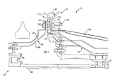
- FIG. 2 is a schematic cross-sectional view of a geared architecture gas turbine engine
- FIG. 3 is a schematic view of a turbine exhaust case module
- FIG. 4 is an expanded sectional view of a triple flange stack according to the disclosed non-limiting embodiment.
- FIG. 2 schematically illustrates a gas turbine engine 20 .
- the gas turbine engine 20 is disclosed herein as a two-spool turbofan that generally incorporates a fan section 22 , a compressor section 24 , a combustor section 26 and a turbine section 28 .
- Alternative engines architectures such as a low-bypass turbofan may include an augmentor section (not shown) among other systems or features.
- turbofan Although schematically illustrated as a turbofan in the disclosed non-limiting embodiment, it should be understood that the concepts described herein are not limited to use with turbofans as the teachings may be applied to other types of turbine engines to include but not limited to a three-spool (plus fan) engine wherein an intermediate spool includes an intermediate pressure compressor (IPC) between a low pressure compressor and a high pressure compressor with an intermediate pressure turbine (IPT) between a high pressure turbine and a low pressure turbine as well as other engine architectures such as turbojets, turboshafts, open rotors and industrial gas turbines.
- IPC intermediate pressure compressor
- IPT intermediate pressure turbine
- the fan section 22 drives air along a bypass flowpath and a core flowpath while the compressor section 24 drives air along the core flowpath for compression and communication into the combustor section 26 then expansion through the turbine section 28 .
- the engine 20 generally includes a low spool 30 and a high spool 32 mounted for rotation about an engine central longitudinal axis A relative to an engine case assembly 36 via several bearing compartments 38 .
- the low spool 30 generally includes an inner shaft 40 that interconnects a fan 42 , a low-pressure compressor 44 (“LPC”) and a low-pressure turbine 46 (“LPT”).
- the inner shaft 40 drives the fan 42 through a geared architecture 48 to drive the fan 42 at a lower speed than the low spool 30 .
- the high spool 32 includes an outer shaft 50 that interconnects a high-pressure compressor 52 (“HPC”) and high-pressure turbine 54 (“HPT”).
- a combustor 56 is arranged between the HPC 52 and the HPT 54 .
- the inner shaft 40 and the outer shaft 50 are concentric and rotate about the engine central longitudinal axis A that is collinear with their longitudinal axes.
- Core airflow is compressed by the LPC 44 then the HPC 52 , mixed with the fuel and burned in the combustor 56 , then expanded over the HPT 54 and the LPT 46 .
- the HPT 54 and the LPT 46 drive the respective low spool 30 and high spool 32 in response to the expansion.
- the gas turbine engine 20 is a high-bypass geared architecture engine in which the bypass ratio is greater than about six (6:1).
- the geared architecture 48 can include an epicyclic gear system 58 , such as a planetary gear system, star gear system or other system.
- the example epicyclic gear train has a gear reduction ratio of greater than about 2.3, and in another example is greater than about 2.5 with a gear system efficiency greater than approximately 98%.
- the geared turbofan enables operation of the low spool 30 at higher speeds which can increase the operational efficiency of the LPC 44 and LPT 46 and render increased pressure in a fewer number of stages.
- a pressure ratio associated with the LPT 46 is pressure measured prior to the inlet of the LPT 46 as related to the pressure at the outlet of the LPT 46 prior to an exhaust nozzle of the gas turbine engine 20 .
- the bypass ratio of the gas turbine engine 20 is greater than about ten (10:1)
- the fan diameter is significantly larger than that of the LPC 44
- the LPT 46 has a pressure ratio that is greater than about five (5:1). It should be understood, however, that the above parameters are only exemplary of one embodiment of a geared architecture engine and that the present disclosure is applicable to other gas turbine engines including direct drive turbofans.
- a significant amount of thrust is provided by the bypass flow due to the high bypass ratio.
- the fan section 22 of the gas turbine engine 20 is designed for a particular flight condition—typically cruise at about 0.8 Mach and about 35,000 feet. This flight condition, with the gas turbine engine 20 at its best fuel consumption, is also known as bucket cruise Thrust Specific Fuel Consumption (TSFC).
- TSFC Thrust Specific Fuel Consumption
- Fan Pressure Ratio is the pressure ratio across a blade of the fan section 22 without a Fan Exit Guide Vane system.
- the low Fan Pressure Ratio according to one non-limiting embodiment of the example gas turbine engine 20 is less than 1.45.
- Low Corrected Fan Tip Speed is the actual fan tip speed divided by an industry standard temperature correction of (“Tram”/518.7) 0.5 .
- the Low Corrected Fan Tip Speed according to one non-limiting embodiment of the example gas turbine engine 20 is less than about 1150 fps (351 m/s).
- the engine case assembly 36 generally includes a plurality of modules to include a fan case module 60 , an intermediate case module 62 , an LPC module 64 , a HPC module 66 , a diffuser module 68 , a HPT module 70 , a mid-turbine frame (MTF) module 72 , a LPT module 74 , and a Turbine Exhaust Case (TEC) module 76 ( FIG. 3 ). It should be understood that additional or alternative modules might be utilized to form the engine case assembly 36 .
- the bearing compartments 38 in the disclosed non-limiting embodiment are defined herein as a forward bearing compartment 38 - 1 , a mid-bearing compartment 38 - 2 axially aft of the forward bearing compartment 38 - 1 , a mid-turbine bearing compartment 38 - 3 axially aft of the mid-bearing compartment 38 - 2 and a rear bearing compartment 38 - 4 axially aft of the mid-turbine bearing compartment 38 - 3 . It should be appreciated that additional or alternative bearing compartments may be provided.
- the TEC module 76 generally includes a case 80 , a forward heat shield 82 , a forward bearing support 84 , a forward bearing 86 , an aft heat shield 88 , an aft bearing support 90 and an aft bearing 92 .
- the forward bearing 86 and the aft bearing 92 are, in the disclosed non-limiting embodiment, the #5 and #6 bearing within the rear bearing compartment 38 - 4 to support the inner shaft 40 of the low spool 30 . It should be appreciated, however, that various bearing compartments will benefit herefrom.
- a flange stack 78 generally includes a case flange 94 of the case 80 secured between a forward flange 96 of the forward bearing support 84 and an aft flange 98 of the aft bearing support 90 by a fastener assembly 100 .
- This allows the radial loading from the relatively higher-temp case flange 94 to pull on the forward bearing support 84 close to a load line through a conical wall 84 W which dramatically reduces the stress in the case flange 94 with relatively thin wall thickness flanges.
- a flange 102 of the forward heat shield 82 and a flange 104 of the aft heat shield 88 may also be secured by the fastener assembly 100 that includes, for example, a bolt 106 and a nut 108 .
- the fastener assembly 100 may be a captured fastener assembly in which the bolt 106 is retained to the forward bearing support 84 even when the aft bearing support 90 is removed. It should be appreciated that numerous fastener assemblies 100 may be utilized about the circumference of the circular flanges 94 , 96 , 98 , 102 , 104 .
- a double pilot snap fit interface 110 is defined between the forward flange 96 and the aft flange 98 .
- the double pilot snap fit interface 110 includes a first axial extension 112 and a second axial extension 114 from the forward flange 96 to define respective surfaces 116 , 118 that form an interference “snap” fit with a respective axial case flange surface 120 of the case flange 94 and a second axial surface 122 of the aft flange 98 .
- a resilient seal 124 may also be located between the second axial surface 122 of the aft flange 98 and the second axial extension 114 of the forward flange 96 .
- the double pilot snap fit interface 110 between the forward flange 96 and the aft flange 98 provides an improved load path to both bearings 86 , 92 .
- the overall stiffness within the TEC module 76 is also facilitated because of the direct load path through the flanges 94 , 96 , 98 .
- the double pilot snap fit interface 110 also shields the high temp case flange 94 from the oil wetted bearing compartment 38 - 4 . Shielding of wetted compartment walls from the relatively high thermal conduction temperatures from the case flange 94 facilitates the prevention of engine oil coking.
- triple flange stack 78 An additional benefit of the triple flange stack 78 is that both bearing supports 84 , 90 share the double pilot snap fit interface 110 to facilitate concentricity of bearings 86 , 92 yet the rear bearing support 90 is readily removed for access and repair of hardware without removal of the forward bearing support 84 .
- a centerline shift of the shaft 40 can be readily achieved with respect to the bearing compartment 38 - 4 relative to the case 80 yet maintain normal bolt clearances.
- the case flange 94 also accommodates a range of centerline shifts as the case flange 94 is sandwiched in the flange stack 78 as compared to conventional architecture ( FIG. 1 ; RELATED ART) that requires offset of the bolt circles of both bearing supports as well as the snap fit.
- triple flange stack 78 may locate the case flange inside the bearing compartment.
Abstract
Description
Claims (18)
Priority Applications (1)
| Application Number | Priority Date | Filing Date | Title |
|---|---|---|---|
| US14/773,865 US10190441B2 (en) | 2013-03-14 | 2014-03-14 | Triple flange arrangement for a gas turbine engine |
Applications Claiming Priority (3)
| Application Number | Priority Date | Filing Date | Title |
|---|---|---|---|
| US201361783271P | 2013-03-14 | 2013-03-14 | |
| US14/773,865 US10190441B2 (en) | 2013-03-14 | 2014-03-14 | Triple flange arrangement for a gas turbine engine |
| PCT/US2014/026963 WO2014152111A1 (en) | 2013-03-14 | 2014-03-14 | Triple flange arrangement for a gas turbine engine |
Publications (2)
| Publication Number | Publication Date |
|---|---|
| US20160032780A1 US20160032780A1 (en) | 2016-02-04 |
| US10190441B2 true US10190441B2 (en) | 2019-01-29 |
Family
ID=51581120
Family Applications (1)
| Application Number | Title | Priority Date | Filing Date |
|---|---|---|---|
| US14/773,865 Active 2035-04-07 US10190441B2 (en) | 2013-03-14 | 2014-03-14 | Triple flange arrangement for a gas turbine engine |
Country Status (3)
| Country | Link |
|---|---|
| US (1) | US10190441B2 (en) |
| EP (1) | EP2971677B1 (en) |
| WO (1) | WO2014152111A1 (en) |
Families Citing this family (6)
| Publication number | Priority date | Publication date | Assignee | Title |
|---|---|---|---|---|
| US9856746B2 (en) * | 2013-03-14 | 2018-01-02 | United Technologies Corporation | Heatshield discourager seal for a gas turbine engine |
| US10823013B2 (en) | 2016-09-30 | 2020-11-03 | General Electric Company | Dual tierod assembly for a gas turbine engine and method of assembly thereof |
| US10746049B2 (en) | 2018-03-30 | 2020-08-18 | United Technologies Corporation | Gas turbine engine case including bearing compartment |
| US10815832B2 (en) | 2018-06-19 | 2020-10-27 | Raytheon Technologies Corporation | Load transfer in turbine exhaust case |
| DE102021124357A1 (en) | 2021-09-21 | 2023-03-23 | MTU Aero Engines AG | Heat protection element for a bearing chamber of a gas turbine |
| FR3127783B1 (en) * | 2021-10-04 | 2023-08-25 | Safran Aircraft Engines | Inter-flange plating control device |
Citations (9)
| Publication number | Priority date | Publication date | Assignee | Title |
|---|---|---|---|---|
| US4074914A (en) | 1975-07-28 | 1978-02-21 | United Technologies Corporation | High pressure lightweight flanges |
| US5433584A (en) | 1994-05-05 | 1995-07-18 | Pratt & Whitney Canada, Inc. | Bearing support housing |
| US20030097844A1 (en) | 2001-11-29 | 2003-05-29 | Seda Jorge F. | Aircraft engine with inter-turbine engine frame |
| US20040063504A1 (en) | 2002-09-26 | 2004-04-01 | Snecma Moteurs | Tension decoupler device |
| US7040098B2 (en) * | 2003-09-19 | 2006-05-09 | Snecma Moteurs | Provision of sealing for the cabin-air bleed cavity of a jet engine using strip-type seals acting in two directions |
| US20060110244A1 (en) | 2004-11-19 | 2006-05-25 | Snecma | Turbomachine with a decoupling device common to first and second bearings of its drive shaft, compressor comprising the decoupling device and decoupling device |
| US20120213629A1 (en) * | 2009-10-08 | 2012-08-23 | Snecma | Device for centering and guiding the rotation of a turbomachine shaft |
| US20120297790A1 (en) | 2011-05-26 | 2012-11-29 | Ioannis Alvanos | Integrated ceramic matrix composite rotor disk geometry for a gas turbine engine |
| WO2014164189A1 (en) | 2013-03-11 | 2014-10-09 | United Technologies Corporation | Heat shield mount configuration |
-
2014
- 2014-03-14 US US14/773,865 patent/US10190441B2/en active Active
- 2014-03-14 EP EP14769860.9A patent/EP2971677B1/en active Active
- 2014-03-14 WO PCT/US2014/026963 patent/WO2014152111A1/en active Application Filing
Patent Citations (9)
| Publication number | Priority date | Publication date | Assignee | Title |
|---|---|---|---|---|
| US4074914A (en) | 1975-07-28 | 1978-02-21 | United Technologies Corporation | High pressure lightweight flanges |
| US5433584A (en) | 1994-05-05 | 1995-07-18 | Pratt & Whitney Canada, Inc. | Bearing support housing |
| US20030097844A1 (en) | 2001-11-29 | 2003-05-29 | Seda Jorge F. | Aircraft engine with inter-turbine engine frame |
| US20040063504A1 (en) | 2002-09-26 | 2004-04-01 | Snecma Moteurs | Tension decoupler device |
| US7040098B2 (en) * | 2003-09-19 | 2006-05-09 | Snecma Moteurs | Provision of sealing for the cabin-air bleed cavity of a jet engine using strip-type seals acting in two directions |
| US20060110244A1 (en) | 2004-11-19 | 2006-05-25 | Snecma | Turbomachine with a decoupling device common to first and second bearings of its drive shaft, compressor comprising the decoupling device and decoupling device |
| US20120213629A1 (en) * | 2009-10-08 | 2012-08-23 | Snecma | Device for centering and guiding the rotation of a turbomachine shaft |
| US20120297790A1 (en) | 2011-05-26 | 2012-11-29 | Ioannis Alvanos | Integrated ceramic matrix composite rotor disk geometry for a gas turbine engine |
| WO2014164189A1 (en) | 2013-03-11 | 2014-10-09 | United Technologies Corporation | Heat shield mount configuration |
Non-Patent Citations (2)
| Title |
|---|
| European Extended Search Report dated Oct. 13, 2016, issued in the corresponding European Patent Application No. 14769860.9. |
| European Office Action dated Apr. 5, 2018, issued in the corresponding European Patent Application No. 14769860.9. |
Also Published As
| Publication number | Publication date |
|---|---|
| US20160032780A1 (en) | 2016-02-04 |
| EP2971677A4 (en) | 2016-11-16 |
| WO2014152111A1 (en) | 2014-09-25 |
| EP2971677A1 (en) | 2016-01-20 |
| EP2971677B1 (en) | 2021-04-28 |
Similar Documents
| Publication | Publication Date | Title |
|---|---|---|
| US9856746B2 (en) | Heatshield discourager seal for a gas turbine engine | |
| US10151240B2 (en) | Mid-turbine frame buffer system | |
| US10100670B2 (en) | Heatshield assembly with double lap joint for a gas turbine engine | |
| US9920641B2 (en) | Gas turbine engine mid-turbine frame configuration | |
| US10190441B2 (en) | Triple flange arrangement for a gas turbine engine | |
| US10174632B2 (en) | Borescope plug assembly for gas turbine engine | |
| US10100672B2 (en) | Fluid-cooled seal arrangement for a gas turbine engine | |
| US9856753B2 (en) | Inner diameter scallop case flange for a case of a gas turbine engine | |
| US9879558B2 (en) | Low leakage multi-directional interface for a gas turbine engine | |
| US10107118B2 (en) | Flow discourager for vane sealing area of a gas turbine engine | |
| US20140241851A1 (en) | Axial oil scoop for a gas turbine engine | |
| US9765649B2 (en) | Borescope inspection port fitting | |
| US11066953B2 (en) | Multi-ply heat shield assembly with integral band clamp for a gas turbine engine | |
| US11008890B2 (en) | Sealing interface for a case of a gas turbine engine | |
| US10156158B2 (en) | Integrated oil supply tube and check valve |
Legal Events
| Date | Code | Title | Description |
|---|---|---|---|
| AS | Assignment |
Owner name: UNITED TECHNOLOGIES CORPORATION, CONNECTICUT Free format text: ASSIGNMENT OF ASSIGNORS INTEREST;ASSIGNORS:GROGG, GARY L;MCCLELLAN, JAMES L, IV;VDOVIAK, GARTH J, JR;REEL/FRAME:036519/0798 Effective date: 20150812 |
|
| STCF | Information on status: patent grant |
Free format text: PATENTED CASE |
|
| AS | Assignment |
Owner name: RAYTHEON TECHNOLOGIES CORPORATION, MASSACHUSETTS Free format text: CHANGE OF NAME;ASSIGNOR:UNITED TECHNOLOGIES CORPORATION;REEL/FRAME:054062/0001 Effective date: 20200403 |
|
| AS | Assignment |
Owner name: RAYTHEON TECHNOLOGIES CORPORATION, CONNECTICUT Free format text: CORRECTIVE ASSIGNMENT TO CORRECT THE AND REMOVE PATENT APPLICATION NUMBER 11886281 AND ADD PATENT APPLICATION NUMBER 14846874. TO CORRECT THE RECEIVING PARTY ADDRESS PREVIOUSLY RECORDED AT REEL: 054062 FRAME: 0001. ASSIGNOR(S) HEREBY CONFIRMS THE CHANGE OF ADDRESS;ASSIGNOR:UNITED TECHNOLOGIES CORPORATION;REEL/FRAME:055659/0001 Effective date: 20200403 |
|
| MAFP | Maintenance fee payment |
Free format text: PAYMENT OF MAINTENANCE FEE, 4TH YEAR, LARGE ENTITY (ORIGINAL EVENT CODE: M1551); ENTITY STATUS OF PATENT OWNER: LARGE ENTITY Year of fee payment: 4 |
|
| AS | Assignment |
Owner name: RTX CORPORATION, CONNECTICUT Free format text: CHANGE OF NAME;ASSIGNOR:RAYTHEON TECHNOLOGIES CORPORATION;REEL/FRAME:064714/0001 Effective date: 20230714 |