RU2343503C2 - Object visualisation method and device within operator-distant region - Google Patents
Object visualisation method and device within operator-distant region Download PDFInfo
- Publication number
- RU2343503C2 RU2343503C2 RU2007108211/28A RU2007108211A RU2343503C2 RU 2343503 C2 RU2343503 C2 RU 2343503C2 RU 2007108211/28 A RU2007108211/28 A RU 2007108211/28A RU 2007108211 A RU2007108211 A RU 2007108211A RU 2343503 C2 RU2343503 C2 RU 2343503C2
- Authority
- RU
- Russia
- Prior art keywords
- radiation
- input
- video signal
- operator
- output
- Prior art date
Links
Images
Landscapes
- Closed-Circuit Television Systems (AREA)
- Optical Radar Systems And Details Thereof (AREA)
Abstract
Description
Изобретение относится к оптической локации, прикладной телевизионной технике и может быть использовано при создании портативных, автомобильных и стационарных систем для наблюдения удаленных объектов в сложных погодных условиях (дымка, пыль, дождь, туман и т.п.), в том числе при наличии фоновой засветки.The invention relates to optical location, applied television technology and can be used to create portable, automotive and stationary systems for monitoring remote objects in difficult weather conditions (haze, dust, rain, fog, etc.), including in the presence of background flare.
Известны устройства для обнаружения и распознавания цели с использованием телевизионных методов обработки сигналов, основанные на эффекте световозвращения, который заключается в излучении импульсного светового потока в направлении объекта поиска (зондирование) и отражении от него части данного потока в обратном направлении с регистрацией разницы в контрасте объекта и фона наблюдателем. Однако в условиях наблюдения через частично прозрачную среду и присутствия фонового излучения в телесном угле наблюдения кроме полезного отраженного излучения присутствует большое количество других фоновых излучений и переотражений. Особым препятствием для визуализации удаленных объектов сквозь полупрозрачную среду является отражение и рассеяние излучения самих устройств обнаружения частицами среды, находящихся в ближних к наблюдателю слоях. Поскольку интенсивность излучения при удалении уменьшается пропорционально квадрату расстояния, а рассеяние излучения средой увеличивается, то рассмотреть какие-либо объекты в дальней зоне на фоне отражения частиц среды, находящихся вблизи осветителя, становится весьма затруднительно. Поэтому для повышения соотношения полезный сигнал/фон, дальности, вероятности и достоверности обнаружения объектов в известных технических решениях реализованы попытки сконцентрировать излучение зондирования в узком телесном угле, разнести направления подсветки и наблюдения, ввести низкочастотную модуляцию (кодирование) излучаемой последовательности с целью выделения объектов поиска по мерцанию их яркости на телевизионном экране и т.п. Однако для наблюдения удаленных объектов в сложных погодных условиях данные способы не эффективны, так как они не устраняют основную причину ухудшения соотношения полезный сигнал/паразитный фон - преобладающего обратного отражения собственного излучения устройства ближними слоями полупрозрачной среды. Увеличение же базового расстояния между излучателем и приемным устройством приводит к неоправданному увеличению размеров устройства, лишает его свойств мобильности и портативности.Known devices for detecting and recognizing targets using television signal processing methods based on the retroreflective effect, which consists in emitting a pulsed light flux in the direction of the search object (sensing) and reflecting part of this flux in the opposite direction from it, recording the difference in the contrast of the object and background by observer. However, in conditions of observation through a partially transparent medium and the presence of background radiation in the solid angle of observation, in addition to the useful reflected radiation, there are a large number of other background radiations and rereflections. A special obstacle to visualization of distant objects through a translucent medium is the reflection and scattering of radiation from the detection devices themselves by particles of the medium located in the layers closest to the observer. Since the radiation intensity decreases as the distance is proportional to the square of the distance, and the scattering of radiation by the medium increases, it becomes very difficult to consider any objects in the far zone against the background of reflection of the particles of the medium located near the illuminator. Therefore, in order to increase the useful signal / background ratio, range, probability and reliability of object detection in known technical solutions, attempts have been made to concentrate sensing radiation in a narrow solid angle, to separate the illumination and observation directions, to introduce low-frequency modulation (coding) of the emitted sequence in order to select search objects by flickering of their brightness on a television screen, etc. However, these methods are not effective for observing distant objects in difficult weather conditions, since they do not eliminate the main reason for the deterioration of the useful signal / spurious background ratio - the prevailing back reflection of the device’s own radiation by the near layers of a translucent medium. An increase in the base distance between the emitter and the receiving device leads to an unjustified increase in the size of the device, depriving it of its mobility and portability properties.
Наиболее близким к предлагаемому решению по технической сути является СПОСОБ ОБНАРУЖЕНИЯ СРЕДСТВ ОПТИЧЕСКОГО И ОПТОЭЛЕКТРОННОГО ТИПА (1). Способ основан на зондировании контролируемого объема пространства сканируемым импульсным лазерным излучением, приеме оптических сигналов изображения с заданной дальности, преобразовании принятых сигналов изображения в видеосигнал, пороговой селекции, зондировании объема пространства с частотой, равной fc/n, и кодировании излучаемой последовательности с частотой fk/m, где fc, fk - соответственно частоты строк и кадров используемого телевизионного метода преобразования сигналов, n, m - натуральные числа, удовлетворяющие условию r≅fc/fk, 2≅m≅fk/2, выявлении сигнала тревоги, а после преобразования видеосигналов в оптическое изображение фиксировании мерцания яркости телевизионного экрана с частотой амплитудной манипуляции. Заявленный технический результат заключается в обнаружении объектов в условиях действия помеховых сигналов.Closest to the proposed solution in technical essence is the METHOD OF DETECTING MEANS OF OPTICAL AND OPTOELECTRONIC TYPE (1). The method is based on sensing the controlled volume of space with scanned pulsed laser radiation, receiving optical image signals from a given range, converting the received image signals into a video signal, threshold selection, sensing the volume of space with a frequency equal to f c / n, and coding the emitted sequence with a frequency f k / m, where f c , f k are the line and frame frequencies of the used television signal conversion method, n, m are natural numbers satisfying the condition r≅f c / f k , 2≅m≅f k / 2, detecting an alarm, and after converting the video signals into an optical image, fixing the flicker of the brightness of the television screen with the frequency of amplitude manipulation. The claimed technical result consists in the detection of objects under the influence of jamming signals.
В данном решении реализовано зондирование сектора наблюдения импульсными посылками с частотой, существенно меньшей, чем строчная, прерываемыми (кодируемыми) с частотой меньшей, чем кадровая, что приводит к мерцанию на экране монитора всего сюжета изображения с периодом кодирования, в то время как составляющая изображения того же сюжета от фоновой подсветки (помеховых сигналов) не изменяет яркости во времени. Данное решение не дает существенного эффекта, так как уровень фоновой засветки в реальных условиях существенно выше средней мощности лазерного излучения устройства, что приводит к незначительной модуляции яркости полезного сигнала на экране монитора. Попытки сконцентрировать излучение, а следовательно, и наблюдение в узком телесном угле приводят к существенным затратам времени на двухкоординатное сканирование всего сектора обзора, а также к материальным затратам на реализацию точного совмещения оптических осей излучателя - приемника и трудозатратам на выполнение их юстировки. Однако главным недостатком данного решения является невозможность его использования в сложных погодных условиях, так как в нем не устраняется преобладающее обратное отражение собственного излучения ближними слоями полупрозрачной среды. Это вытекает из того, что в данном решении отсутствует механизм синхронного приема с заданного расстояния отражений излученных посылок, т.е. привязка процесса приема (накопления) сигналов устройством ко времени поступления отражений излучения с учетом задержки на распространение излучения до объекта и обратно. Утверждение же о «…приеме оптических сигналов изображения с заданной дальности…» технически ничем не подтверждается, так как при асинхронном приеме суммарного отраженного (информативного) и фонового потоков они принимаются фотоприемником и с ближнего и с дальнего расстояния во всем широком спектре чувствительности фотоприемника.This solution implements sensing of the observation sector with pulse transmissions with a frequency substantially lower than the lowercase, interrupted (encoded) with a frequency lower than the frame frequency, which leads to flickering on the monitor screen of the entire image plot with the coding period, while the image component of the same scene from the backlight (interfering signals) does not change the brightness over time. This solution does not give a significant effect, since the level of background illumination in real conditions is significantly higher than the average laser radiation power of the device, which leads to insignificant modulation of the brightness of the useful signal on the monitor screen. Attempts to concentrate the radiation and, consequently, the observation in a narrow solid angle lead to significant time spent on two-axis scanning of the entire viewing sector, as well as material costs for the exact alignment of the optical axes of the emitter - receiver and labor for adjusting them. However, the main disadvantage of this solution is the impossibility of its use in difficult weather conditions, since it does not eliminate the prevailing inverse reflection of intrinsic radiation by the adjacent layers of a translucent medium. This follows from the fact that in this solution there is no mechanism for synchronous reception from a given distance of reflections of emitted packets, i.e. binding the process of receiving (accumulating) signals by the device to the time of arrival of radiation reflections, taking into account the delay in the propagation of radiation to the object and back. The statement about "... the reception of optical image signals from a given range ..." is not technically confirmed, since with asynchronous reception of the total reflected (informative) and background streams they are received by the photodetector from both near and far distances in the whole wide spectrum of the sensitivity of the photodetector.
Технической задачей настоящего изобретения является повышение дальности, вероятности и достоверности визуализации, поиска, обнаружения и распознавания объектов, находящихся в зоне на заданном удалении от оператора, в условиях наблюдения через частично прозрачную среду и присутствия фонового излучения при одновременном уменьшении времени поиска объектов, мощности излучения, размеров, массы и стоимости устройства.An object of the present invention is to increase the range, likelihood and reliability of visualization, search, detection and recognition of objects located in a zone at a predetermined distance from the operator, under conditions of observation through a partially transparent medium and the presence of background radiation while reducing the search time of objects, radiation power, dimensions, mass and cost of the device.
Поставленная задача решается способом и устройством визуализации объектов, находящихся в зоне на заданном удалении от оператора, основанным на импульсном зондировании контролируемой зоны излучением со спектральным составом, соответствующим спектру отражения обнаруживаемых объектов, приеме отраженного излучения, преобразовании данного излучения в видеосигнал и далее в видимое для оператора изображение контролируемой зоны, отличающимся тем, что длительность однократно или многократно повторяющихся в каждом периоде визуализации импульсов зондирования задают равной отношению глубины просматриваемой зоны по дальности к скорости света, прием отраженного излучения производят с предварительной оптической фильтрацией в диапазоне длин волн, соответствующем спектру излучения, а однократное или многократное накопление в процессе преобразования отфильтрованных отражений излучения с заданной дальности в видеосигнал в каждом периоде визуализации с длительностью, равной длительности зондирования, производят только в интервалах времени, задержанных относительно временных интервалов импульсного зондирования на величину отношения двойного удаления зоны от оператора к скорости света.The problem is solved by the method and device for visualizing objects located in a zone at a predetermined distance from the operator, based on pulsed sounding of a controlled zone by radiation with a spectral composition corresponding to the reflection spectrum of detected objects, receiving reflected radiation, converting this radiation into a video signal and then into a visible signal for the operator image of the controlled area, characterized in that the duration of once or repeatedly repeated in each period of visualization them sounding pulses are set equal to the ratio of the depth of the viewed zone in range to the speed of light, reception of reflected radiation is carried out with preliminary optical filtering in the wavelength range corresponding to the radiation spectrum, and one-time or multiple accumulation in the process of converting the filtered radiation reflections from a given range into a video signal in each period visualizations with a duration equal to the duration of sounding are performed only in time intervals delayed relative to time GOVERNMENTAL pulse intervals sensing the magnitude relationship double deletion area from the operator to the speed of light.
При этом предлагается вариант, в котором для каждого четного периода визуализации импульсное зондирование излучением не производят, накопление в процессе преобразования принятых излучений в видеосигнал производят в каждом периоде, после накопления выполняют раздельное запоминание совокупности отсчетов видеосигналов для нечетных и четных периодов визуализации, далее производят вычитание соответствующих отсчетов видеосигналов четных периодов из отсчетов нечетных, а затем визуализацию разностного видеосигнала.At the same time, a variant is proposed in which no pulsed sounding is performed for each even period of visualization, accumulation during the conversion of received radiations into a video signal is made in each period, after accumulation separate storage of the set of samples of video signals for odd and even periods of visualization is performed, then the corresponding video samples of even periods from odd samples, and then visualization of the differential video signal.
Устройство для визуализации объектов, находящихся в зоне на заданном удалении от оператора, в условиях наблюдения через частично прозрачную среду и присутствия фонового излучения, содержащее телевизионную камеру с объективом и формирователем импульсов накопления, соединенную с монитором, и импульсный источник излучения, отличающееся тем, что в него введен оптический фильтр, установленный перед фотоприемником телевизионной камеры, с полосой пропускания, соответствующей рабочему спектру управляемого импульсного источника излучения, а также перестраиваемый блок управления длительностью и задержкой, введенный в состав телевизионной камеры, один выход которого подключен ко входу управляемого импульсного источника излучения, другой - ко входу формирователя импульсов накопления телевизионной камеры, а оптические оси объектива телевизионной камеры и управляемого импульсного источника излучения, расположенных вблизи друг от друга, однонаправлены.A device for visualizing objects located in a zone at a predetermined distance from the operator, in conditions of observation through a partially transparent medium and the presence of background radiation, comprising a television camera with a lens and an accumulator pulse generator connected to the monitor, and a pulsed radiation source, characterized in that he introduced an optical filter mounted in front of the photodetector of a television camera, with a passband corresponding to the working spectrum of a controlled pulsed radiation source, also a tunable control unit for the duration and delay introduced into the television camera, one output of which is connected to the input of the controlled pulsed radiation source, the other to the input of the pulse shaper of the accumulation of the television camera, and the optical axis of the lens of the television camera and the controlled pulsed radiation source, located close to each other from a friend, unidirectional.
При этом предлагается вариант, в котором в разрыв между выходом телевизионной камеры и входом монитора включен формирователь разностного видеосигнала, состоящий из аналого-цифрового преобразователя, первого и второго блоков памяти, блока вычитания, мультиплексора и цифроаналогового преобразователя, причем к выходу телевизионной камеры подключен вход аналого-цифрового преобразователя, являющийся входом формирователя разностного видеосигнала, к выходу аналого-цифрового преобразователя подключен первый вход блока вычитания и через первый блок памяти - второй вход блока вычитания, выход которого подключен к первому входу мультиплексора и через второй блок памяти - ко второму входу мультиплексора, выход мультиплексора подключен ко входу цифроаналогового преобразователя, а выход последнего, являющийся выходом формирователя разностного видеосигнала, соединен со входом монитора.At the same time, a variant is proposed in which a difference video signal shaper is included in the gap between the output of the television camera and the monitor input, consisting of an analog-to-digital converter, the first and second memory blocks, a subtraction unit, a multiplexer, and a digital-to-analog converter, and an analog input is connected to the output of the television camera -digital converter, which is the input of the differential video signal former, the first input of the subtraction unit is connected to the output of the analog-to-digital converter, and through the first memory block is the second input of the subtraction block, the output of which is connected to the first input of the multiplexer and through the second memory block to the second input of the multiplexer, the output of the multiplexer is connected to the input of the digital-to-analog converter, and the output of the latter, which is the output of the differential video signal former, is connected to the monitor input.
Устройство, функциональная схема которого представлена на фиг.1, реализованное в соответствии с предлагаемым способом, работает следующим образом:A device whose functional diagram is presented in figure 1, implemented in accordance with the proposed method, operates as follows:
При включении телевизионной камеры 1 перестраиваемый блок 2 управления длительностью и задержкой, введенный в состав телевизионной камеры 1 и синхронизируемый ее синхрогенератором, формирует импульсы управления заданной длительности. Длительность этих импульсов задается оператором равной отношению глубины просматриваемой зоны по дальности к скорости света. Данные импульсы поступают на вход управляемого импульсного источника 3 излучения, который в ответ на них формирует импульсный поток с ограниченным спектром излучения видимого или ближнего инфракрасного диапазона, причем длительность импульсов излучения равна длительности импульсов, поступающих на его вход. Ширина диаграммы направленности импульсного источника 3 излучения в вертикальной и горизонтальной плоскости сопоставима с телесным углом наблюдения телевизионной камеры 1, определяемым фокусным расстоянием объектива 4. Телевизионная камера 1 с объективом 4 располагается в непосредственной близости от источника 3 излучения, а их оптические оси однонаправлены.When the television camera 1 is turned on, the tunable control unit 2 for the duration and delay introduced into the television camera 1 and synchronized by its sync generator generates control pulses of a given duration. The duration of these pulses is set by the operator equal to the ratio of the depth of the viewed zone in range to the speed of light. These pulses are fed to the input of a controlled pulsed radiation source 3, which in response to them forms a pulsed stream with a limited emission spectrum of the visible or near infrared range, and the duration of the radiation pulses is equal to the duration of the pulses received at its input. The width of the radiation pattern of the pulsed radiation source 3 in the vertical and horizontal plane is comparable with the solid angle of observation of the television camera 1, determined by the focal length of the lens 4. The television camera 1 with the lens 4 is located in the immediate vicinity of the radiation source 3, and their optical axes are unidirectional.
Излучаемый импульсный поток зондирует окружающее пространство (сектор поиска) и его часть, отраженная от находящихся на заданном удалении физических тел и объектов поиска, возвращается в обратном направлении через время, равное времени распространения излучения до заданной зоны и обратно, т.е. равное удвоенному расстоянию до зоны, деленному на скорость света. Возвращенная часть потока, попадает во входное окно объектива 4, практически без потерь проходит через оптический фильтр 5, полоса пропускания которого совпадает со спектром излучения источника 3, и фокусируется на рабочей плоскости фотоприемника телевизионной камеры 1. В момент поступления первых фотонов отраженного пакета с заданной дальности перестраиваемый блок 2 управления длительностью и задержкой на втором своем выходе формирует импульсы управления, поступающие на вход формирователя 6 импульсов накопления телевизионной камеры. Формирователь 6, входящий в состав телевизионной камеры 1, в ответ на это обеспечивает синхронное управление накоплением (приемом) в фотоприемнике носителей сигнала, причем длительность формируемых им импульсов накопления строго равна длительности импульсов излучения. Таким образом, данное накопление в телевизионной камере 1 происходит с наперед заданной оператором задержкой, равной удвоенному расстоянию до зоны просмотра, деленному на скорость света, а длительность процесса накопления задается равной длительности временного интервала излучения, т.е. отношению глубины просматриваемой зоны по дальности к скорости света.The emitted pulse stream probes the surrounding space (search sector) and its part, reflected from physical bodies and search objects located at a given distance, returns in the opposite direction after a time equal to the propagation time of the radiation to the given zone and vice versa, i.e. equal to twice the distance to the zone divided by the speed of light. The returned part of the stream enters the input window of the lens 4, passes almost without loss through the optical filter 5, the passband of which coincides with the radiation spectrum of the source 3, and focuses on the working plane of the photodetector of television camera 1. At the time the first photons of the reflected packet arrive at a given range the tunable control unit 2 for the duration and delay at its second output generates control pulses received at the input of the shaper 6 of the accumulation pulses of the television camera. The shaper 6, which is part of the television camera 1, in response to this provides synchronous control of the accumulation (reception) in the photodetector of the signal carriers, and the duration of the accumulation pulses formed by it is strictly equal to the duration of the radiation pulses. Thus, this accumulation in the television camera 1 occurs with a delay set in advance by the operator equal to twice the distance to the viewing area divided by the speed of light, and the duration of the accumulation process is set equal to the duration of the radiation time interval, i.e. the ratio of the depth of the viewed zone in range to the speed of light.
Поэтому на экране монитора 7, видеовход которого соединен с выходом видеосигнала телевизионной камеры 1, визуализируется сюжет с яркостным выделением объектов только в зоне, глубина и удаленность которой задаются оператором, что и служит основанием для принятия им решения об обнаружении и распознавании объектов поиска. Для перестройки глубины или удаленности зоны просмотра с помощью перестраиваемого блока 2 управления оператором соответственно изменяется длительность импульсов излучения и накопления или задержка накопления носителей сигнала.Therefore, on the screen of the monitor 7, the video input of which is connected to the video signal output of the television camera 1, the plot is visualized with the brightness highlighting of objects only in the zone, the depth and remoteness of which are set by the operator, which serves as the basis for him to make a decision on the detection and recognition of search objects. To adjust the depth or remoteness of the viewing area using the tunable operator control unit 2, the duration of the radiation pulses and the accumulation or delay of accumulation of the signal carriers accordingly changes.
При использовании устройства в условиях присутствия подавляющей фоновой засветки (естественный солнечный свет, различные осветители и т.п.) в объектив 4 телевизионной камеры 1 кроме полезного отраженного импульсного излучения попадают и фоновые (паразитные) излучения и переотражения от окружающих предметов и сооружений. Уровень фонового потока излучения в заданном телесном угле наблюдения в точке приема иногда существенно превышает средний уровень полезного сигнала, отраженного от объекта поиска. Ширина спектра фонового излучения также много больше ширины спектра отраженного полезного сигнала. Однако широкоспектральное фоновое излучение, проходя через оптический фильтр 5, существенно ограничивается по спектру, что приводит к многократному уменьшению его мощности, а следовательно, и составляющей паразитного фона в видеосигнале, формируемом камерой 1.When using the device in the presence of overwhelming background illumination (natural sunlight, various illuminators, etc.), in addition to the useful reflected pulsed radiation, background (spurious) radiation and rereflection from surrounding objects and structures also enter the lens 4 of the television camera 1. The level of the background radiation flux at a given solid angle of observation at the receiving point sometimes significantly exceeds the average level of the useful signal reflected from the search object. The spectrum width of the background radiation is also much larger than the spectrum width of the reflected useful signal. However, the wide-spectrum background radiation passing through the optical filter 5 is substantially limited in spectrum, which leads to a multiple decrease in its power and, consequently, in the component of the spurious background in the video signal generated by camera 1.
При использовании устройства для наблюдения через частично прозрачную среду эффект подавления паразитного фона и отражения собственного излучения ближними слоями среды в предлагаемом техническом решении достигается за счет реализации синхронного приема отражений управляемого импульсного излучения источника 3. Излучающими компонентами могут быть лазерные устройства, светодиоды видимого и ИК-диапазона с ограниченным (узким) спектром излучения и т.п. излучатели с фокусирующей оптикой или без нее. Так как накопление носителей сигналов при приеме излучений телевизионной камерой 1 в предлагаемом устройстве разрешается только в интервалах времени, задержанных относительно временных интервалов импульсного зондирования, то паразитное фоновое излучение вне этих интервалов фотоприемником камеры 1 не накапливается и не создает дополнительных составляющих в видеосигнале. Скважность следования импульсов излучения и скважность импульсов разрешения накопления может составлять от десятков до тысяч. Почти в такое же количество раз импульсная мощность излучателя 3 может кратковременно превышать его среднюю допустимую мощность. Выбор количества посылок излучения (однократные или многократные) и соответственно количества фаз накопления носителей сигналов с суммированием их результатов в каждом периоде визуализации (поле, кадр и т.п.) может производиться с учетом возможности конкретных видов излучателей выдерживать соответствующие импульсные нагрузки. По параметру подавления паразитного фона предлагаемое устройство обеспечивает выигрыш, сопоставимый с выбранной скважностью, по сравнению с устройствами, работающими в режиме асинхронного импульсного излучения и накопления. Подавление же отражения собственного излучения устройства ближними слоями полупрозрачной среды происходит потому, что в период приема отражений от этих слоев накопление носителей сигнала в фотоприемнике камеры 1 запрещено.When using a device for observing through a partially transparent medium, the effect of suppressing spurious background and reflection of intrinsic radiation by the near layers of the medium in the proposed technical solution is achieved by implementing synchronous reception of reflections of controlled pulsed radiation of source 3. The emitting components can be laser devices, visible and IR LEDs with a limited (narrow) emission spectrum, etc. emitters with focusing optics or without it. Since the accumulation of signal carriers when receiving radiation by the television camera 1 in the proposed device is allowed only in time intervals delayed relative to the time intervals of pulse sounding, spurious background radiation outside these intervals by the photodetector of camera 1 does not accumulate and does not create additional components in the video signal. The duty cycle of the radiation pulses and the duty cycle of the accumulation resolution pulses can range from tens to thousands. Almost the same number of times the pulsed power of the emitter 3 can briefly exceed its average allowable power. The choice of the number of radiation packets (single or multiple) and, accordingly, the number of phases of accumulation of signal carriers with summation of their results in each visualization period (field, frame, etc.) can be made taking into account the possibility of specific types of emitters to withstand the corresponding pulsed loads. According to the parasitic background suppression parameter, the proposed device provides a gain comparable to the selected duty cycle compared to devices operating in the mode of asynchronous pulsed radiation and accumulation. The suppression of the reflection of the self-radiation of the device by the near layers of a translucent medium occurs because during the period of receiving reflections from these layers, the accumulation of signal carriers in the photodetector of camera 1 is prohibited.
Таким образом, в реализации предлагаемых способа и устройства длительность однократно или многократно повторяющихся в каждом периоде визуализации импульсов зондирования задают равной отношению глубины просматриваемой зоны по дальности к скорости света, прием отраженного излучения производят с предварительной оптической фильтрацией в диапазоне длин волн, соответствующем спектру излучения, а однократное или многократное накопление в процессе преобразования отфильтрованных отражений излучения с заданной дальности в видеосигнал в каждом периоде визуализации с длительностью, равной длительности зондирования, производят только в интервалах времени, задержанных относительно временных интервалов импульсного зондирования на величину отношения двойного удаления зоны от оператора к скорости света.Thus, in the implementation of the proposed method and device, the duration of sounding pulses that are once or repeatedly repeated in each visualization period is set equal to the ratio of the depth of the viewed zone in range to the speed of light, the reflected radiation is received with preliminary optical filtering in the wavelength range corresponding to the radiation spectrum, and single or multiple accumulation during the conversion of filtered radiation reflections from a given range into a video signal in Each visualization period with a duration equal to the sounding duration is performed only in time intervals delayed relative to the time intervals of pulsed sounding by the ratio of the double distance of the zone from the operator to the speed of light.
Одной из телевизионных камер, способных обеспечивать работу в режиме с однократным или многократным управляемым накоплением зарядов в течение поля или кадра при длительности каждой из фаз накопления в десятки и сотни наносекунд, является, например, специализированная камера VNC-748-H3 на основе ПЗС-матрицы с чувствительностью 0,00004 люкс (ЗАО «ЭВС», С-Петербург, Россия). В ней имеется режим программирования наперед заданного времени управления излучателем, накопления зарядов (по длительности и времени задержки), в том числе с реализацией одно- или многократного кратковременного накопления в каждой текущей, каждой второй, четвертой и т.д. строке с суммированием и сохранением накопленных зарядовых пакетов к концу каждого полукадра. Предусмотрен и прогрессивный режим развертки с сохранением результата накопления к концу кадра. В этом случае функции перестраиваемого блока 2 управления длительностью и задержкой, синхрогенератора и формирователя 6 импульсов накопления телевизионной камеры 1 выполняет программируемый процессор на основе ПЛИС ф. «Altera» указанной камеры. Причем в этом варианте исполнения для каждого периода визуализации может производиться многократное импульсное зондирование и соответствующее задержанное многократное накопление с суммированием сигналов в процессе преобразования отраженных излучений в видеосигнал.One of the television cameras capable of operating in the mode with single or multiple controlled accumulation of charges during a field or frame with a duration of each of the accumulation phases of tens and hundreds of nanoseconds is, for example, a specialized VNC-748-H3 camera based on a CCD with a sensitivity of 0.00004 lux (ZAO EVS, St. Petersburg, Russia). It has a programming mode for a predetermined time for controlling the emitter, accumulation of charges (in duration and delay time), including with the implementation of one or multiple short-term accumulations in each current, every second, fourth, etc. line with the summation and storage of accumulated charge packets to the end of each half frame. A progressive scan mode is also provided with saving the accumulation result to the end of the frame. In this case, the functions of the tunable block 2 control the duration and delay, the clock and the shaper 6 pulses of accumulation of the television camera 1 performs a programmable processor based on FPGA f. "Altera" specified camera. Moreover, in this embodiment, for each visualization period, multiple pulse sensing and the corresponding delayed multiple accumulation with the summation of the signals in the process of converting reflected radiation into a video signal can be performed.
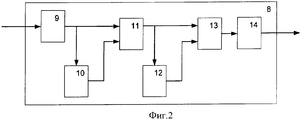
Для дальнейшего повышения качества визуализации объектов, находящихся в зоне на заданном удалении от оператора, в условиях наблюдения через частично прозрачную среду при одновременном присутствии выраженного фонового излучения предлагается вариант устройства, в котором в разрыв между выходом видеосигнала телевизионной камеры 1 и входом монитора 7 включен формирователь 8 разностного видеосигнала, изображенный на фиг.2. При этом на вход аналого-цифрового преобразователя 9, являющегося входом формирователя 8, поступает видеосигнал от камеры 1. В преобразователе 9 происходит оцифровка данного видеосигнала, после чего с его многоразрядного выхода цифровой сигнал подается на первый вход блока 10 памяти. В блоке 10 происходит запоминание совокупности отсчетов видеосигнала и их задержка на период визуализации (поле, кадр чересстрочной развертки, кадр прогрессивной развертки и т.п.). Прямой с выхода преобразователя 9 и задержанный в блоке 10 видеосигналы в цифровой форме далее поступают на входы блока 11 вычитания, в котором из отсчетов текущего видеосигнала вычитаются соответствующие отсчеты предыдущего (задержанного). Затем цифровой видеосигнал межкадровой и т.п. разности с выхода блока 11 вычитания поступает через блок 12 памяти на один из входов мультиплексора 13. Блок 12 памяти производит задержку разностного сигнала также на период визуализации. На другой вход мультиплексора 13 поступает незадержанный разностный сигнал. Мультиплексор 13 при этом выполняет функцию выбора полярности разностного видеосигнала (либо вычитания сигнала четного периода из сигнала нечетного, либо наоборот), а также функцию повторного воспроизведения разности с выбранной полярностью. Следовательно, период смены информации на выходе мультиплексора 13 составляет удвоенный период визуализации (например, два кадра). С выхода мультиплексора 13 разностный видеосигнал поступает на многоразрядный вход цифро-аналогового преобразователя 14, с выхода которого, являющегося выходом формирователя 8 разностного видеосигнала, далее в аналоговой форме поступает на вход монитора 7 для визуализации.To further improve the quality of visualization of objects located in a zone at a predetermined distance from the operator, under conditions of observation through a partially transparent medium with the simultaneous presence of pronounced background radiation, a variant of the device is proposed in which a
Кроме того, в этом режиме визуализации перестраиваемый блок 2 управления длительностью и задержкой в каждом четном периоде визуализации не выдает импульсов управления излучателем 3, но выдает на вход формирователя 6 импульсы для управления накоплением телевизионной камеры 1 каждый период. При этом в нечетных периодах видеосигнала содержится информация о сумме составляющей полезного сигнала, отраженного при импульсном зондировании от объектов удаленной зоны, и составляющей фонового излучения. В четных же периодах в видеосигнале присутствует только информация о составляющей фонового излучения. После процесса выполнения межкадрового и т.п. вычитания это приводит к тому, что в разностном видеосигнале составляющая постоянного (медленно изменяющегося во времени) фонового излучения существенно уменьшается. В вариантах реализации способа возможны и иные конфигурации формирователя 8 разностного видеосигнала.In addition, in this visualization mode, the tunable control unit 2 for the duration and delay in each even period of the visualization does not give control pulses to the emitter 3, but gives pulses to the input of the shaper 6 to control the accumulation of the television camera 1 every period. Moreover, in odd periods of the video signal contains information about the sum of the component of the useful signal reflected during pulsed sounding from objects in the remote zone, and the component of the background radiation. In even periods, the video signal contains only information about the component of the background radiation. After the process of performing inter-frame, etc. subtraction, this leads to the fact that in the difference video signal the component of the constant (slowly changing in time) background radiation is significantly reduced. In embodiments of the method, other configurations of a differential video signal former 8 are also possible.
Таким образом, реализуется вариант, в котором для каждого четного периода визуализации импульсное зондирование излучением не производят, накопление в процессе преобразования принятых излучений в видеосигнал производят в каждом периоде, после накопления выполняют раздельное запоминание совокупности отсчетов видеосигналов для нечетных и четных периодов визуализации, далее производят вычитание соответствующих отсчетов видеосигналов четных периодов из отсчетов нечетных, а затем визуализацию разностного видеосигнала.Thus, a variant is realized in which pulsed sounding is not performed for each even visualization period, accumulation during the conversion of the received radiations into a video signal is made in each period, after accumulation separate storage of the set of video signal samples for odd and even visualization periods is performed, then subtraction is performed corresponding video samples of even periods from odd samples, and then visualization of the differential video signal.
Результатом реализации предложенного технического решения является повышение дальности, вероятности и достоверности визуализации, поиска, обнаружения и распознавания объектов, находящихся в зоне на заданном удалении от оператора, в условиях наблюдения через частично прозрачную среду (дымка, пыль, дождь, туман, редкий лес, кустарник и т.п.) и присутствия фонового излучения при одновременном уменьшении времени поиска объектов, мощности излучения, размеров, массы и стоимости устройства. Это является следствием синхронного приема ответных посылок и значительного повышения отношения полезного сигнала отражения от объектов из удаленной зоны к паразитному фону в относительно широком телесном угле излучения и наблюдения, что позволяет существенно увеличить эквивалентную контрастность объектов поиска на экране монитора относительно других объектов изображения.The result of the implementation of the proposed technical solution is to increase the range, likelihood and reliability of visualization, search, detection and recognition of objects located in the zone at a predetermined distance from the operator, under observation conditions through a partially transparent medium (haze, dust, rain, fog, rare forest, shrubs etc.) and the presence of background radiation while reducing the time to search for objects, radiation power, size, mass and cost of the device. This is a consequence of the synchronous reception of response messages and a significant increase in the ratio of the useful reflection signal from objects from the remote zone to the spurious background in a relatively wide solid angle of radiation and observation, which can significantly increase the equivalent contrast of search objects on the monitor screen relative to other image objects.
Расширенный телесный угол излучения и наблюдения обеспечивает уменьшение времени поиска за счет исключения многократного (пошагового) сканирования заданного сектора по двум координатам или сокращения количества шагов, а также упрощение и уменьшение габаритных размеров оптических систем излучателя и приемника (телевизионной камеры), исключение сложных технологических операций по их взаимной юстировке, что приводит к уменьшению размеров, массы и стоимости устройства обнаружения.The expanded solid angle of radiation and observation provides a reduction in search time by eliminating multiple (step-by-step) scanning of a given sector in two coordinates or reducing the number of steps, as well as simplifying and reducing the overall dimensions of the optical systems of the emitter and receiver (television camera), eliminating complex technological operations by their mutual alignment, which leads to a decrease in the size, weight and cost of the detection device.
Использованная литератураReferences
1. Патент РФ № 2133485, 1999 г.1. RF patent No. 2133485, 1999
Claims (4)
Priority Applications (1)
| Application Number | Priority Date | Filing Date | Title |
|---|---|---|---|
| RU2007108211/28A RU2343503C2 (en) | 2007-03-05 | 2007-03-05 | Object visualisation method and device within operator-distant region |
Applications Claiming Priority (1)
| Application Number | Priority Date | Filing Date | Title |
|---|---|---|---|
| RU2007108211/28A RU2343503C2 (en) | 2007-03-05 | 2007-03-05 | Object visualisation method and device within operator-distant region |
Publications (2)
| Publication Number | Publication Date |
|---|---|
| RU2007108211A RU2007108211A (en) | 2008-09-10 |
| RU2343503C2 true RU2343503C2 (en) | 2009-01-10 |
Family
ID=39866638
Family Applications (1)
| Application Number | Title | Priority Date | Filing Date |
|---|---|---|---|
| RU2007108211/28A RU2343503C2 (en) | 2007-03-05 | 2007-03-05 | Object visualisation method and device within operator-distant region |
Country Status (1)
| Country | Link |
|---|---|
| RU (1) | RU2343503C2 (en) |
Cited By (1)
| Publication number | Priority date | Publication date | Assignee | Title |
|---|---|---|---|---|
| RU214866U1 (en) * | 2022-10-24 | 2022-11-17 | Общество С Ограниченной Ответственностью "Линзаплюс" | Wide spectrum fluid lens |
Citations (4)
| Publication number | Priority date | Publication date | Assignee | Title |
|---|---|---|---|---|
| SU654056A1 (en) * | 1976-08-20 | 1987-04-15 | Институт физики АН БССР | Device for generating current pulses of alternating direction |
| RU2094815C1 (en) * | 1994-10-08 | 1997-10-27 | Государственный центральный научно-исследовательский радиотехнический институт | Simulator of radio sources |
| RU2099730C1 (en) * | 1996-03-01 | 1997-12-20 | Государственное научно-производственное предприятие "Прибор" | Process forming information field of teleorientation laser system and gear for its realization |
| RU57472U1 (en) * | 2006-05-22 | 2006-10-10 | Производственное объединение "Уральский оптико-механический завод" (ПО "УОМЗ") | ACTIVE PULSE TELEVISION DEVICE |
-
2007
- 2007-03-05 RU RU2007108211/28A patent/RU2343503C2/en not_active IP Right Cessation
Patent Citations (4)
| Publication number | Priority date | Publication date | Assignee | Title |
|---|---|---|---|---|
| SU654056A1 (en) * | 1976-08-20 | 1987-04-15 | Институт физики АН БССР | Device for generating current pulses of alternating direction |
| RU2094815C1 (en) * | 1994-10-08 | 1997-10-27 | Государственный центральный научно-исследовательский радиотехнический институт | Simulator of radio sources |
| RU2099730C1 (en) * | 1996-03-01 | 1997-12-20 | Государственное научно-производственное предприятие "Прибор" | Process forming information field of teleorientation laser system and gear for its realization |
| RU57472U1 (en) * | 2006-05-22 | 2006-10-10 | Производственное объединение "Уральский оптико-механический завод" (ПО "УОМЗ") | ACTIVE PULSE TELEVISION DEVICE |
Cited By (1)
| Publication number | Priority date | Publication date | Assignee | Title |
|---|---|---|---|---|
| RU214866U1 (en) * | 2022-10-24 | 2022-11-17 | Общество С Ограниченной Ответственностью "Линзаплюс" | Wide spectrum fluid lens |
Also Published As
| Publication number | Publication date |
|---|---|
| RU2007108211A (en) | 2008-09-10 |
Similar Documents
| Publication | Publication Date | Title |
|---|---|---|
| AU626157B2 (en) | Imaging lidar system using non-visible light | |
| KR102165399B1 (en) | Gated Sensor Based Imaging System With Minimized Delay Time Between Sensor Exposures | |
| JP2938912B2 (en) | Imaging Rider System | |
| JP7086001B2 (en) | Adaptive optical raider receiver | |
| US5164823A (en) | Imaging lidar system employing multipulse single and multiple gating for single and stacked frames | |
| JPH03188322A (en) | Method for image-forming two wavelength original position of single internal wave | |
| EP3935411A1 (en) | Systems, methods, and media for single photon depth imaging with improved precision in ambient light | |
| CN110579773A (en) | Single photon laser radar detection system and method based on multiple detectors | |
| US20120249781A1 (en) | Method consisting of pulsing a laser communicating with a gated-sensor so as to reduce speckle, reduce scintillation, improve laser beam uniformity and improve eye safety in laser range gated imagery | |
| CN101536051A (en) | Sensor for presence detection | |
| CN111751802A (en) | A photon-level adaptive high-sensitivity spatial weak target detection system and detection method | |
| US20250008240A1 (en) | Imaging system and method with adaptive scanning active illumination | |
| CN110749902A (en) | A 3D imaging system and imaging method based on time segmentation | |
| RU2343503C2 (en) | Object visualisation method and device within operator-distant region | |
| Jin et al. | Scannerless non-line-of-sight three dimensional imaging with a 32x32 SPAD array | |
| RU2597889C2 (en) | Gated television system with a pulsed illumination source | |
| RU2349929C2 (en) | Optical and optoelectronic device detector | |
| CN101681777A (en) | System for artificially enhancing image display contrast | |
| RU2263931C1 (en) | Device for observing objects | |
| RU2278399C2 (en) | Method for detecting optical and optical-electronic surveillance means and device for realization of said method | |
| Baranov et al. | Multi-pulse active CCD television system model for 3D imaging | |
| EP4369032A1 (en) | Optical sensing system | |
| RU2007108119A (en) | METHOD AND DEVICE FOR DETECTION OF OPTICAL AND OPTOELECTRONIC OBJECTS |
Legal Events
| Date | Code | Title | Description |
|---|---|---|---|
| TK4A | Correction to the publication in the bulletin (patent) |
Free format text: AMENDMENT TO CHAPTER -FG4A- IN JOURNAL: 1-2009 |
|
| MM4A | The patent is invalid due to non-payment of fees |
Effective date: 20110306 |