RU2343329C2 - Double-speed manual drive of pipeline valves - Google Patents
Double-speed manual drive of pipeline valves Download PDFInfo
- Publication number
- RU2343329C2 RU2343329C2 RU2006120042/06A RU2006120042A RU2343329C2 RU 2343329 C2 RU2343329 C2 RU 2343329C2 RU 2006120042/06 A RU2006120042/06 A RU 2006120042/06A RU 2006120042 A RU2006120042 A RU 2006120042A RU 2343329 C2 RU2343329 C2 RU 2343329C2
- Authority
- RU
- Russia
- Prior art keywords
- cover
- switch
- shaft
- planetary gear
- speed
- Prior art date
Links
Images
Landscapes
- Operating, Guiding And Securing Of Roll- Type Closing Members (AREA)
- Connection Of Motors, Electrical Generators, Mechanical Devices, And The Like (AREA)
- Mechanically-Actuated Valves (AREA)
Abstract
Description
Изобретение относится к области машиностроения и может быть использовано в качестве привода для трубопроводной запорно-регулирующей арматуры.The invention relates to the field of mechanical engineering and can be used as a drive for pipeline valves.
Известно двухскоростное приводное устройство для управления трубопроводной арматурой, содержащее электродвигатель с планетарным механизмом, работающим как редуктор, фрикционную предохранительную муфту и кулачковую муфту, кинематически связанную с выходным валом, при этом кулачковая муфта оснащена переключающим устройством, выполненным в виде подпружиненных собачек, управляемых посредством поводка от нажимного диска, подпружиненного в осевом направлении и зафиксированного от поворота относительно ведущей шестерни планетарного редуктора (см. а.с. N493584, М. кл. F16K 31/53, СССР, БИ № 44-1975).A two-speed drive device for controlling pipe fittings is known, comprising an electric motor with a planetary mechanism operating as a gearbox, a friction clutch and a cam clutch kinematically connected with the output shaft, while the cam clutch is equipped with a switching device made in the form of spring-loaded dogs controlled by a lead from axial pressure disk, fixed from rotation relative to the planetary drive gear duktora (see. AS N493584, M. Cl. F16K 31/53, USSR BI № 44-1975).
Известное устройство позволяет автоматически изменять скорость вращения выходного вала редуктора в зависимости от заданного крутящего момента, однако оно является конструктивно сложным и ненадежным в работе из-за наличия фрикционной муфты. Кроме того, оно предназначено преимущественно для приводов с электродвигателем.The known device allows you to automatically change the speed of rotation of the output shaft of the gearbox depending on a given torque, however, it is structurally difficult and unreliable in operation due to the presence of a friction clutch. In addition, it is intended primarily for drives with an electric motor.
Наиболее близким к предлагаемому по технической сущности и достигаемому эффекту является привод задвижки, выполненный в виде установленного на ее корпусе двухступенчатого планетарного механизма, работающего как редуктор, сателлиты которого связывают маховик через солнечное колесо со вторым солнечным колесом, закрепленным на одном из элементов механизма перемещения запорного органа. Привод содержит тормозное устройство, установленное на корпусе редуктора и выполненное в виде подпружиненного фиксатора, взаимодействующего или с корпусом задвижки, или со вторым солнечным колесом (см. а.с. N476402, М. кл. F16K 31/53, СССР, БИ № 25-1975).The closest to the proposed technical essence and the achieved effect is the valve actuator, made in the form of a two-stage planetary gear mounted on its body, operating as a gearbox, the satellites of which connect the flywheel through the sun wheel to the second sun wheel mounted on one of the elements of the shutter body movement mechanism . The drive contains a brake device mounted on the gearbox housing and made in the form of a spring-loaded latch, interacting with either the valve body or the second sun wheel (see AS N476402, M. class. F16K 31/53, USSR, BI No. 25 -1975).
Недостатками известного устройства являются сложность конструкции и увеличенные габариты, обусловленные необходимостью в исполнении редуктора двухступенчатым, а также неудобство в эксплуатации, вызванное обязательным наличием двух фиксаторов и необходимостью вращать весь редуктор вместе с корпусом во время работы на второй скорости. Кроме того, при переключении скоростей (расфиксации корпуса редуктора) редуктор получает две степени свободы, что затрудняет фиксацию второго солнечного колеса, а наличие открытых отверстий под фиксаторы, незащищенных от инородных частиц, снижает надежность устройства. Конструкция известного привода позволяет уменьшить усилие, прилагаемое к маховику в наиболее нагруженные моменты - «страгивания с места» и «запирания», но не обеспечивает его быстродействие в менее нагруженные моменты.The disadvantages of the known device are the design complexity and increased dimensions, due to the need for a two-stage gearbox, as well as inconvenience in operation caused by the mandatory presence of two clamps and the need to rotate the entire gearbox together with the housing during operation at second speed. In addition, when switching speeds (unlocking the gear case), the gearbox receives two degrees of freedom, which makes it difficult to fix the second sun wheel, and the presence of open holes for the latches, unprotected from foreign particles, reduces the reliability of the device. The design of the known drive allows you to reduce the force exerted on the flywheel in the most loaded moments - "moving away" and "locking", but does not ensure its speed in less stressed moments.
Техническая задача, решаемая в предлагаемом устройстве, - создание двухскоростного ручного привода с повышенным быстродействием, конструктивно простого, удобного и надежного в эксплуатации.The technical problem solved in the proposed device is the creation of a two-speed manual drive with increased speed, structurally simple, convenient and reliable in operation.
Поставленная задача решается с помощью того, что в двухскоростном ручном приводе, включающем размещенный в корпусе с крышкой планетарный механизм, выходное солнечное колесо которого закреплено на валу, связанном с механизмом перемещения запорного органа арматуры, маховик и переключатель скорости, крышка корпуса планетарного механизма установлена в корпусе с возможностью вращения, маховик жестко закреплен на ней, а переключатель размещен на крышке с возможностью взаимодействия или с валом солнечного колеса планетарного механизма, или с его водилом через выполненный в крышке паз.The problem is solved by the fact that in a two-speed manual drive including a planetary mechanism located in a housing with a cover, the output sun wheel of which is mounted on a shaft connected to the valve locking mechanism, the flywheel and speed switch, the planetary gear housing cover is installed in the housing with the possibility of rotation, the flywheel is rigidly fixed to it, and the switch is placed on the cover with the possibility of interaction with either the shaft of the solar wheel of the planetary mechanism, or with his carrier through a groove made in the lid.
Переключатель может быть выполнен в виде поворотного рычага, а вал солнечного колеса планетарного механизма снабжен фланцем, при этом на периферии фланца и на водило планетарного механизма выполнены незамкнутые пазы, взаимодействующие с рычагом переключателя в его соответствующих положениях.The switch can be made in the form of a rotary lever, and the shaft of the planetary gear sun wheel is provided with a flange, while open grooves are made on the periphery of the flange and on the planet carrier of the planet gear, interacting with the switch lever in its corresponding positions.
Размещение маховика и переключателя на крышке корпуса планетарного механизма, установленной с возможностью вращения в корпусе, и взаимодействие переключателя или с валом солнечного колеса, или с водилом делают привод удобным в эксплуатации и конструктивно более простым, т.к. планетарный механизм теперь может быть выполнен одноступенчатым. При этом планетарный механизм работает в режиме мультипликатора, повышая быстродействие привода в менее нагруженные моменты перемещения запорного органа арматуры.The placement of the flywheel and the switch on the cover of the planetary gear housing mounted rotatably in the housing, and the interaction of the switch with either the shaft of the sun wheel or the carrier make the drive convenient to operate and structurally simpler, because planetary gear can now be performed in single-stage. In this case, the planetary mechanism operates in the multiplier mode, increasing the speed of the drive at less loaded moments of movement of the valve body.
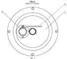
Сущность технического решения поясняется чертежами, где на фиг.1 изображен разрез двухскоростного привода, на фиг.2 - вид по стрелке А со стороны маховика.The essence of the technical solution is illustrated by drawings, where in Fig.1 shows a section of a two-speed drive, in Fig.2 is a view along arrow A from the side of the flywheel.
Предлагаемый привод содержит размещенный в корпусе 1 с крышкой 2 планетарный механизм, включающий вал 3 с солнечным колесом 4, связанный с исполнительным механизмом (не показан), коронное колесо 5 и водило 6 с сателлитами 7. Крышка 2 установлена в корпусе 1 с возможностью вращения в подшипниках 8. На крышке 2 жестко закреплены маховик 9 и корпус переключателя 10, в котором на оси 11 размещен переключатель - поворотный рычаг 12. На конце вала 3 солнечного колеса размещен фланец 13 с пазами 14, на водиле 6 выполнены аналогичные пазы 15. Переключатель 12 установлен с возможностью взаимодействия или с пазами 14 фланца 13, или с пазами 15 водила 6. Изменение положения переключателя осуществляют с помощью рукоятки 16 через паз 17 в крышке 2.The proposed drive comprises a planetary mechanism located in the housing 1 with a
Привод работает следующим образом. При открытии, например, клиновой задвижки для страгивания запорного органа (клина) поворотный рычаг 12 устанавливают посредством рукоятки 16 в паз 14 фланца 13 и, вращая маховик 9, передают крутящий момент непосредственно на вал 3. После страгивания запорного органа рычаг 12 перемещают в паз 15 водила, передавая крутящий момент на вал 3 солнечного колеса через сателлиты 7, при этом планетарный механизм работает в режиме мультипликатора, увеличивая скорость перемещения запорного органа.The drive operates as follows. When opening, for example, a wedge gate valve for stragging the locking element (wedge), the pivoting lever 12 is installed by means of the
При закрытии клиновой задвижки сначала рычаг 12 устанавливают в паз 15 водила и производят перемещение запорного органа через мультипликатор с увеличенной скоростью до соприкосновения уплотнительных полей запорного органа с ответными полями его корпуса. После чего рычаг переключателя 12 перемещают в паз 14 фланца 13 и усилие от маховика 9 передают непосредственно на вал 3 и запорный орган до полной герметизации.When the wedge gate valve is closed, first, the lever 12 is installed in the carrier groove 15 and the locking element is moved through the multiplier at an increased speed until the sealing fields of the locking element come into contact with the response fields of its body. After that, the lever of the switch 12 is moved into the groove 14 of the flange 13 and the force from the flywheel 9 is transmitted directly to the shaft 3 and the locking element until complete sealing.
При использовании привода для регулирующей арматуры возможность изменения скорости перемещения запорного органа позволяет производить более точную настройку регулирующего органа.When using a actuator for control valves, the possibility of changing the speed of movement of the locking element allows for more precise adjustment of the regulatory body.
Таким образом, применение в предлагаемом приводе одноступенчатого планетарного механизма, размещение переключателя на крышке его корпуса обуславливают простоту его конструкции, а отсутствие открытых полостей повышает его надежность. При этом работа планетарного механизма в режиме мультипликатора позволяет значительно снизить время управления арматурой.Thus, the use of a one-stage planetary mechanism in the proposed drive, the placement of the switch on the cover of its housing, determine the simplicity of its design, and the absence of open cavities increases its reliability. At the same time, the operation of the planetary mechanism in the multiplier mode can significantly reduce the time of control of the valve.
Claims (2)
Priority Applications (1)
| Application Number | Priority Date | Filing Date | Title |
|---|---|---|---|
| RU2006120042/06A RU2343329C2 (en) | 2006-06-07 | 2006-06-07 | Double-speed manual drive of pipeline valves |
Applications Claiming Priority (1)
| Application Number | Priority Date | Filing Date | Title |
|---|---|---|---|
| RU2006120042/06A RU2343329C2 (en) | 2006-06-07 | 2006-06-07 | Double-speed manual drive of pipeline valves |
Publications (2)
| Publication Number | Publication Date |
|---|---|
| RU2006120042A RU2006120042A (en) | 2007-12-27 |
| RU2343329C2 true RU2343329C2 (en) | 2009-01-10 |
Family
ID=39018421
Family Applications (1)
| Application Number | Title | Priority Date | Filing Date |
|---|---|---|---|
| RU2006120042/06A RU2343329C2 (en) | 2006-06-07 | 2006-06-07 | Double-speed manual drive of pipeline valves |
Country Status (1)
| Country | Link |
|---|---|
| RU (1) | RU2343329C2 (en) |
Cited By (2)
| Publication number | Priority date | Publication date | Assignee | Title |
|---|---|---|---|---|
| RU2454590C2 (en) * | 2009-06-08 | 2012-06-27 | Общество с ограниченной ответственностью "МЕХАНИК" | Double-speed hand drive of pipeline valves |
| RU2659681C1 (en) * | 2017-04-24 | 2018-07-03 | федеральное государственное бюджетное образовательное учреждение высшего образования "Ижевский государственный технический университет имени М.Т. Калашникова" | Two-speed hand drive of shut-off valve |
-
2006
- 2006-06-07 RU RU2006120042/06A patent/RU2343329C2/en not_active IP Right Cessation
Cited By (2)
| Publication number | Priority date | Publication date | Assignee | Title |
|---|---|---|---|---|
| RU2454590C2 (en) * | 2009-06-08 | 2012-06-27 | Общество с ограниченной ответственностью "МЕХАНИК" | Double-speed hand drive of pipeline valves |
| RU2659681C1 (en) * | 2017-04-24 | 2018-07-03 | федеральное государственное бюджетное образовательное учреждение высшего образования "Ижевский государственный технический университет имени М.Т. Калашникова" | Two-speed hand drive of shut-off valve |
Also Published As
| Publication number | Publication date |
|---|---|
| RU2006120042A (en) | 2007-12-27 |
Similar Documents
| Publication | Publication Date | Title |
|---|---|---|
| US4659141A (en) | Safety device for vehicle sun roof | |
| JPS59118970A (en) | Door lock apparatus for automobile | |
| RU2659681C1 (en) | Two-speed hand drive of shut-off valve | |
| WO1992022766A1 (en) | Feedback motor-operated valve | |
| CN110242770B (en) | Three-way ball valve | |
| RU2413114C1 (en) | Manual two-speed drive for multi-purpose accessories | |
| RU2343329C2 (en) | Double-speed manual drive of pipeline valves | |
| KR20150125965A (en) | Motor vehicle door closure | |
| AU2007222304A1 (en) | Sprung anti-backing-off device | |
| US8224228B2 (en) | Cover closer | |
| US3946984A (en) | Motor-driven control device for a valve rod | |
| JP5316876B2 (en) | Pump device | |
| US20070256747A1 (en) | Motor driven valve | |
| JP2007071357A (en) | Electric actuator | |
| JP4994085B2 (en) | Valve actuator | |
| CN206828811U (en) | Washing machine and its speed-reducing clutch | |
| RU2454590C2 (en) | Double-speed hand drive of pipeline valves | |
| WO2009078279A1 (en) | Valve opening degree detection device and valve opening/closing device | |
| TWI606957B (en) | Internal transmission control mechanism | |
| JP3291261B2 (en) | Opening / closing device for rotary valve with auxiliary valve | |
| RU2008105657A (en) | MECHANISM FOR DRIVING VALVE IN ACTION, DEVICE FOR DRIVING VALVE IN ACTION AND VALVE | |
| GB2199897A (en) | An extractor fan | |
| KR101031212B1 (en) | Electrically-powered apparatus for opening and closing valve | |
| JP3599129B2 (en) | Centrifugal clutch | |
| RU189060U1 (en) | TWO-SPEED DRIVE FOR PIPELINE VALVES |
Legal Events
| Date | Code | Title | Description |
|---|---|---|---|
| MM4A | The patent is invalid due to non-payment of fees |
Effective date: 20090608 |