RU2340983C1 - Accumulator battery that has increased protection - Google Patents
Accumulator battery that has increased protection Download PDFInfo
- Publication number
- RU2340983C1 RU2340983C1 RU2007117136/09A RU2007117136A RU2340983C1 RU 2340983 C1 RU2340983 C1 RU 2340983C1 RU 2007117136/09 A RU2007117136/09 A RU 2007117136/09A RU 2007117136 A RU2007117136 A RU 2007117136A RU 2340983 C1 RU2340983 C1 RU 2340983C1
- Authority
- RU
- Russia
- Prior art keywords
- battery
- conductive substrate
- electrically conductive
- battery case
- negative electrode
- Prior art date
Links
Images
Classifications
-
- H—ELECTRICITY
- H01—ELECTRIC ELEMENTS
- H01M—PROCESSES OR MEANS, e.g. BATTERIES, FOR THE DIRECT CONVERSION OF CHEMICAL ENERGY INTO ELECTRICAL ENERGY
- H01M50/00—Constructional details or processes of manufacture of the non-active parts of electrochemical cells other than fuel cells, e.g. hybrid cells
- H01M50/20—Mountings; Secondary casings or frames; Racks, modules or packs; Suspension devices; Shock absorbers; Transport or carrying devices; Holders
-
- H—ELECTRICITY
- H01—ELECTRIC ELEMENTS
- H01M—PROCESSES OR MEANS, e.g. BATTERIES, FOR THE DIRECT CONVERSION OF CHEMICAL ENERGY INTO ELECTRICAL ENERGY
- H01M50/00—Constructional details or processes of manufacture of the non-active parts of electrochemical cells other than fuel cells, e.g. hybrid cells
- H01M50/10—Primary casings, jackets or wrappings of a single cell or a single battery
- H01M50/116—Primary casings, jackets or wrappings of a single cell or a single battery characterised by the material
- H01M50/124—Primary casings, jackets or wrappings of a single cell or a single battery characterised by the material having a layered structure
- H01M50/1243—Primary casings, jackets or wrappings of a single cell or a single battery characterised by the material having a layered structure characterised by the internal coating on the casing
-
- H—ELECTRICITY
- H01—ELECTRIC ELEMENTS
- H01M—PROCESSES OR MEANS, e.g. BATTERIES, FOR THE DIRECT CONVERSION OF CHEMICAL ENERGY INTO ELECTRICAL ENERGY
- H01M10/00—Secondary cells; Manufacture thereof
- H01M10/05—Accumulators with non-aqueous electrolyte
- H01M10/052—Li-accumulators
- H01M10/0525—Rocking-chair batteries, i.e. batteries with lithium insertion or intercalation in both electrodes; Lithium-ion batteries
-
- H—ELECTRICITY
- H01—ELECTRIC ELEMENTS
- H01M—PROCESSES OR MEANS, e.g. BATTERIES, FOR THE DIRECT CONVERSION OF CHEMICAL ENERGY INTO ELECTRICAL ENERGY
- H01M50/00—Constructional details or processes of manufacture of the non-active parts of electrochemical cells other than fuel cells, e.g. hybrid cells
- H01M50/10—Primary casings, jackets or wrappings of a single cell or a single battery
- H01M50/116—Primary casings, jackets or wrappings of a single cell or a single battery characterised by the material
- H01M50/117—Inorganic material
- H01M50/119—Metals
-
- H—ELECTRICITY
- H01—ELECTRIC ELEMENTS
- H01M—PROCESSES OR MEANS, e.g. BATTERIES, FOR THE DIRECT CONVERSION OF CHEMICAL ENERGY INTO ELECTRICAL ENERGY
- H01M50/00—Constructional details or processes of manufacture of the non-active parts of electrochemical cells other than fuel cells, e.g. hybrid cells
- H01M50/10—Primary casings, jackets or wrappings of a single cell or a single battery
- H01M50/116—Primary casings, jackets or wrappings of a single cell or a single battery characterised by the material
- H01M50/121—Organic material
-
- H—ELECTRICITY
- H01—ELECTRIC ELEMENTS
- H01M—PROCESSES OR MEANS, e.g. BATTERIES, FOR THE DIRECT CONVERSION OF CHEMICAL ENERGY INTO ELECTRICAL ENERGY
- H01M50/00—Constructional details or processes of manufacture of the non-active parts of electrochemical cells other than fuel cells, e.g. hybrid cells
- H01M50/10—Primary casings, jackets or wrappings of a single cell or a single battery
- H01M50/116—Primary casings, jackets or wrappings of a single cell or a single battery characterised by the material
- H01M50/124—Primary casings, jackets or wrappings of a single cell or a single battery characterised by the material having a layered structure
- H01M50/126—Primary casings, jackets or wrappings of a single cell or a single battery characterised by the material having a layered structure comprising three or more layers
- H01M50/128—Primary casings, jackets or wrappings of a single cell or a single battery characterised by the material having a layered structure comprising three or more layers with two or more layers of only inorganic material
-
- H—ELECTRICITY
- H01—ELECTRIC ELEMENTS
- H01M—PROCESSES OR MEANS, e.g. BATTERIES, FOR THE DIRECT CONVERSION OF CHEMICAL ENERGY INTO ELECTRICAL ENERGY
- H01M50/00—Constructional details or processes of manufacture of the non-active parts of electrochemical cells other than fuel cells, e.g. hybrid cells
- H01M50/10—Primary casings, jackets or wrappings of a single cell or a single battery
- H01M50/131—Primary casings, jackets or wrappings of a single cell or a single battery characterised by physical properties, e.g. gas-permeability or size
- H01M50/133—Thickness
-
- Y—GENERAL TAGGING OF NEW TECHNOLOGICAL DEVELOPMENTS; GENERAL TAGGING OF CROSS-SECTIONAL TECHNOLOGIES SPANNING OVER SEVERAL SECTIONS OF THE IPC; TECHNICAL SUBJECTS COVERED BY FORMER USPC CROSS-REFERENCE ART COLLECTIONS [XRACs] AND DIGESTS
- Y02—TECHNOLOGIES OR APPLICATIONS FOR MITIGATION OR ADAPTATION AGAINST CLIMATE CHANGE
- Y02E—REDUCTION OF GREENHOUSE GAS [GHG] EMISSIONS, RELATED TO ENERGY GENERATION, TRANSMISSION OR DISTRIBUTION
- Y02E60/00—Enabling technologies; Technologies with a potential or indirect contribution to GHG emissions mitigation
- Y02E60/10—Energy storage using batteries
-
- Y—GENERAL TAGGING OF NEW TECHNOLOGICAL DEVELOPMENTS; GENERAL TAGGING OF CROSS-SECTIONAL TECHNOLOGIES SPANNING OVER SEVERAL SECTIONS OF THE IPC; TECHNICAL SUBJECTS COVERED BY FORMER USPC CROSS-REFERENCE ART COLLECTIONS [XRACs] AND DIGESTS
- Y02—TECHNOLOGIES OR APPLICATIONS FOR MITIGATION OR ADAPTATION AGAINST CLIMATE CHANGE
- Y02P—CLIMATE CHANGE MITIGATION TECHNOLOGIES IN THE PRODUCTION OR PROCESSING OF GOODS
- Y02P70/00—Climate change mitigation technologies in the production process for final industrial or consumer products
- Y02P70/50—Manufacturing or production processes characterised by the final manufactured product
Abstract
Description
Область техники, к которой относится изобретениеFIELD OF THE INVENTION
Настоящее изобретение относится к аккумуляторной батарее с усовершенствованной защитой, а также к защитному устройству, используемому для этого.The present invention relates to a battery with improved protection, as well as to a protective device used for this.
Уровень техникиState of the art
В общем, аккумуляторные батареи являются перезаряжаемыми батареями, которые могут изготовляться компактными или крупногабаритными. Например, аккумуляторные батареи включают в себя никель-металгидридные батареи, литиевые батареи и литиево-ионные батареи. Помимо этого, аккумуляторные батареи классифицируются на цилиндрические аккумуляторные батареи и квадратные аккумуляторные батареи согласно своему внешнему виду.In general, rechargeable batteries are rechargeable batteries that can be manufactured compact or oversized. For example, rechargeable batteries include nickel metal hydride batteries, lithium batteries, and lithium ion batteries. In addition, batteries are classified into cylindrical batteries and square batteries according to their appearance.
В отличие от аккумуляторной батареи пакетного типа цилиндрическая аккумуляторная батарея или квадратная аккумуляторная батарея включает в себя корпус батареи, выступающий в качестве клеммы положительного электрода или клеммы отрицательного электрода, и электродный комплект, помещенный в корпус батареи и включающий в себя положительный электрод (катод), покрытый активным веществом положительного электрода, отрицательный электрод (анод), покрытый активным веществом отрицательного электрода, и сепаратор, размещенный между положительным и отрицательным электродом.Unlike a batch type battery, a cylindrical battery or square battery includes a battery case acting as a positive electrode terminal or a negative electrode terminal, and an electrode set placed in a battery case and including a positive electrode (cathode) coated the active substance of the positive electrode, the negative electrode (anode) coated with the active substance of the negative electrode, and a separator located between the positive th and negative electrode.
Между тем, если острый инструмент, такой как гвоздь или наконечник сверла, проникает через положительный и отрицательный электроды, покрытые активными веществами, посредством прохождения через корпус батареи, или если на корпус батареи нажимают посредством прессовального инструмента, такого как тиски, внутреннее короткое замыкание может возникнуть между положительным и отрицательным электродом, так что ток большой величины возникает между положительным и отрицательным электродом, что сопровождается выделением тепла. В экстремальной ситуации батарея подвергается воспламенению или взрыву. По этой причине в батарее предусмотрено защитное устройство для предотвращения случайного воспламенения или взрыва батареи.Meanwhile, if a sharp tool, such as a nail or drill tip, penetrates the positive and negative electrodes coated with active substances by passing through the battery case, or if the battery case is pressed with a pressing tool such as a vice, internal short circuiting may occur between the positive and negative electrode, so that a large current arises between the positive and negative electrode, which is accompanied by heat generation. In extreme situations, the battery will ignite or explode. For this reason, a protective device is provided in the battery to prevent accidental ignition or explosion of the battery.
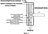
Например, не прошедшая экспертизу японская патентная публикация номер 2000-48852 раскрывает защитное устройство для аккумуляторной батареи, показанное на фиг.1, при этом защитное устройство предоставляется во внешней части электродного комплекта в форме рулона, который помещается в корпус цилиндрической батареи посредством продления положительных и отрицательных электродов без покрытия, на которые не нанесены активные вещества на заранее определенную длину. Корпус батареи электрически изолирован от положительного электрода без покрытия или отрицательного электрода без покрытия посредством сепаратора, и корпус батареи может выступать в качестве клеммы положительного электрода или клеммы отрицательного электрода батареи.For example, Japanese Patent Publication No. 2000-48852, which has not passed examination, discloses the protective device for the battery shown in FIG. 1, and the protective device is provided on the outside of the electrode kit in the form of a roll, which is placed in the housing of the cylindrical battery by extending the positive and negative uncoated electrodes on which active substances are not applied to a predetermined length. The battery case is electrically isolated from the positive electrode without coating or the negative electrode without coating by means of a separator, and the battery case can act as a terminal of the positive electrode or terminal of the negative electrode of the battery.
Согласно вышеупомянутому предшествующему уровню техники, если острый инструмент проникает в электродный комплект через корпус батареи, возникает короткое замыкание между положительными и отрицательными электродами без покрытия, имеющими относительно более низкое сопротивление, а также возникает короткое замыкание между положительными и отрицательными электродами, имеющими относительно более высокое сопротивление, которые сформированы с помощью активных веществ. В этот момент ток короткого замыкания главным образом может протекать между положительными и отрицательными электродами без покрытия, имеющими относительно меньшее сопротивление, так чтобы величина тока, применяемая к положительным и отрицательным электродам, имеющим активные вещества, снижалась. Таким образом, корпус батареи может быть защищен даже в том случае, если в батарее возникает внутреннее короткое замыкание, тем самым не допуская внезапного генерирования тепла и внезапного повышения температуры в батарее.According to the aforementioned prior art, if a sharp tool penetrates the electrode assembly through the battery case, a short circuit occurs between the positive and negative uncoated electrodes having a relatively lower resistance, and a short circuit occurs between the positive and negative electrodes having a relatively higher resistance which are formed using active substances. At this point, the short-circuit current can mainly flow between the positive and negative uncoated electrodes having a relatively lower resistance, so that the current applied to the positive and negative electrodes having active substances decreases. Thus, the battery case can be protected even if an internal short circuit occurs in the battery, thereby preventing sudden generation of heat and a sudden increase in temperature in the battery.
Тем не менее, согласно вышеупомянутой традиционной цилиндрической батарее короткое замыкание может возникать только в том случае, когда острый инструмент, такой как гвоздь или наконечник сверла, проникает в отрицательный и положительный электроды без покрытия после прохождения корпуса батареи, так чтобы заряженный ток в корпусе батареи не мог быстро разрядиться во внешнюю область в то время, когда острый инструмент проникает в корпус батареи.However, according to the aforementioned traditional cylindrical battery, a short circuit can occur only when a sharp tool, such as a nail or drill tip, penetrates the negative and positive electrodes without coating after passing through the battery case, so that the charged current in the battery case does not could quickly be discharged into the external area at the time when a sharp instrument penetrates the battery case.
Помимо этого положительные и отрицательные электроды без покрытия ориентированы рядом с положительными и отрицательными электродами, покрытыми активными веществами, и положительные и отрицательные электроды без покрытия имеют толщину, относительно меньшую толщины корпуса батареи. Таким образом, если острый инструмент, вставленный в корпус батареи, дополнительно перемещается в направлении положительных и отрицательных электродов, покрытых активными веществами, и проникает в положительные и отрицательные электроды, может внезапно произойти высокотемпературный нагрев в корпусе батареи, так что батарея подвергается случайному возгоранию или взрыву.In addition, the positive and negative electrodes without coating are oriented next to the positive and negative electrodes coated with active substances, and the positive and negative electrodes without coating have a thickness relatively smaller than the thickness of the battery case. Thus, if a sharp instrument inserted into the battery case further moves towards the positive and negative electrodes coated with active substances and penetrates the positive and negative electrodes, high temperature heating may suddenly occur in the battery case, so that the battery is subjected to accidental fire or explosion .
Краткое описание чертежейBrief Description of the Drawings
На фиг.1 показан частичный схематичный вид в разрезе, иллюстрирующий традиционную цилиндрическую батарею.1 is a partial schematic sectional view illustrating a conventional cylindrical battery.
На фиг.2 показан частичный схематичный вид в разрезе, иллюстрирующий аккумуляторную батарею согласно первому варианту осуществления настоящего изобретения.2 is a partial schematic cross-sectional view illustrating a secondary battery according to a first embodiment of the present invention.
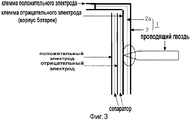
На фиг.3 показан частичный схематичный вид в разрезе, иллюстрирующий аккумуляторную батарею согласно первому варианту осуществления настоящего изобретения, в котором гвоздь частично проникает в аккумуляторную батарею.FIG. 3 is a partial schematic cross-sectional view illustrating a secondary battery according to a first embodiment of the present invention, in which a nail partially penetrates the secondary battery.
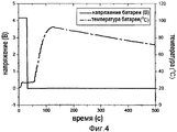
На фиг.4 показан график, иллюстрирующий варьирование температуры и напряжения аккумуляторной батареи как функцию от времени, когда аккумуляторная батарея согласно первому примеру настоящего изобретения заряжена с помощью 4,2 В, и гвоздь, имеющий диаметр 2 мм, полностью проникает в аккумуляторную батарею.4 is a graph illustrating the variation in temperature and voltage of a battery as a function of time when the battery according to the first example of the present invention is charged with 4.2 V and a nail having a diameter of 2 mm penetrates completely into the battery.
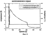
На фиг.5 показан график, иллюстрирующий варьирование температуры и напряжения традиционной цилиндрической батареи как функцию от времени, когда традиционная цилиндрическая батарея заряжена с помощью 4,2 В и гвоздь, имеющий диаметр 2 мм, полностью проникает в традиционную цилиндрическую батарею.5 is a graph illustrating temperature and voltage variation of a conventional cylindrical battery as a function of time when the traditional cylindrical battery is charged with 4.2 V and a nail having a diameter of 2 mm penetrates completely into the traditional cylindrical battery.
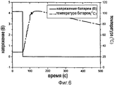
На фиг.6 показан график, иллюстрирующий варьирование температуры и напряжения аккумуляторной батареи как функцию от времени, когда аккумуляторная батарея согласно первому примеру настоящего изобретения заряжена с помощью 4,2 В и гвоздь, имеющий диаметр 2 мм, частично проникает в корпус батареи извне на расстояние 8 мм.6 is a graph illustrating the variation in temperature and voltage of a battery as a function of time when the battery according to the first example of the present invention is charged with 4.2 V and a nail having a diameter of 2 mm partially penetrates into the battery case from a distance 8 mm.
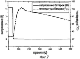
На фиг.7 показан график, иллюстрирующий варьирование температуры и напряжения аккумуляторной батареи как функцию от времени, когда аккумуляторная батарея согласно первому примеру настоящего изобретения заряжена с помощью 4,2 В и гвоздь, имеющий диаметр 2 мм, частично проникает в корпус батареи извне на расстояние 4 мм.7 is a graph illustrating the variation in temperature and voltage of a battery as a function of time when the battery according to the first example of the present invention is charged with 4.2 V and a nail having a diameter of 2 mm partially penetrates the battery case from a
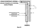
На фиг.8 показан частичный схематичный вид в разрезе, иллюстрирующий аккумуляторную батарею согласно второму варианту осуществления настоящего изобретения.FIG. 8 is a partial schematic cross-sectional view illustrating a secondary battery according to a second embodiment of the present invention.
На чертежах номер 1 представляет защитное устройство, 2a представляет непроводящую пленку, 2 представляет электропроводящую подложку, а 3 представляет жесткий кожух.In the drawings,
Раскрытие изобретенияDisclosure of invention
Таким образом, настоящее изобретение выполнено для разрешения вышеупомянутых проблем, возникающих в предшествующем уровне техники, и цель настоящего изобретения заключается в обеспечении защиты цилиндрической батареи или квадратной батареи от внешних факторов, таких как проникновение острого инструмента (к примеру, гвоздя или наконечника сверла), сжимающей силы инструмента (к примеру, тисков), внешнего воздействия и воздействия высокой температуры. Подробнее, цель настоящего изобретения заключается в генерировании внешнего короткого замыкания вне корпуса батареи, когда внешние факторы применяются к корпусу батареи, с тем чтобы заряженный ток в аккумуляторной батареи мог в достаточной степени разряжаться из аккумуляторной батареи до того, как внешние факторы окажут негативное воздействие на аккумуляторную батарею (к примеру, внутреннее короткое замыкание в электродном комплекте, размещенном в корпусе батареи). Таким образом, защита аккумуляторной батареи может обеспечиваться даже в том случае, если между положительным электродом и отрицательным электродом аккумуляторной батареи возникает внутреннее короткое замыкание, вызванное внешними факторами.Thus, the present invention is made to solve the above problems arising in the prior art, and the aim of the present invention is to protect the cylindrical battery or square battery from external factors, such as the penetration of a sharp tool (for example, a nail or drill tip), compressing the strength of the tool (for example, a vice), external exposure and exposure to high temperature. More specifically, an object of the present invention is to generate an external short circuit outside the battery case when external factors are applied to the battery case so that the charged current in the battery can be sufficiently discharged from the battery before external factors negatively affect the battery a battery (for example, an internal short circuit in an electrode kit located in a battery case). Thus, protection of the battery can be ensured even if an internal short circuit caused by external factors occurs between the positive electrode and the negative electrode of the battery.
Чтобы достичь вышеуказанной цели, настоящее изобретение предоставляет аккумуляторная батарея, при этом батарея содержит: корпус батареи, выступающий в качестве клеммы положительного электрода или клеммы отрицательного электрода; электропроводящую подложку, предусмотренную во внешней части корпуса батареи; и непроводящую пленку, помещенную между корпусом батареи и электропроводящей подложкой, для изолирования электропроводящей подложки от корпуса батареи, при этом электропроводящая подложка электрически соединена с клеммой терминала, имеющей полярность, противоположную полярности корпуса батареи.In order to achieve the above object, the present invention provides a secondary battery, the battery comprising: a battery case serving as a positive electrode terminal or a negative electrode terminal; an electrically conductive substrate provided in the outer part of the battery case; and a non-conductive film placed between the battery case and the conductive substrate to isolate the conductive substrate from the battery case, wherein the conductive substrate is electrically connected to a terminal terminal having a polarity opposite to that of the battery case.
Согласно предпочтительному варианту осуществления настоящего изобретения электропроводящая подложка крепится к внутренней стенке непроводящего жесткого кожуха, а непроводящий жесткий кожух окружает, по меньшей мере, часть аккумуляторной батареи в состоянии, в котором часть двух клемм электродов выступает наружу.According to a preferred embodiment of the present invention, the electrically conductive substrate is attached to the inner wall of the non-conductive rigid casing, and the non-conductive rigid casing surrounds at least a portion of the battery in a state in which part of the two electrode terminals protrudes outward.
Помимо этого настоящее изобретение предоставляет защитное устройство, предусмотренное во внешней части корпуса батареи, выступающего в качестве клеммы положительного электрода или клеммы отрицательного электрода аккумуляторной батареи, при этом защитное устройство включает в себя электропроводящую подложку, предусмотренную с одной стороны, с непроводящей пленкой.In addition, the present invention provides a protective device provided in an outer part of a battery case serving as a positive electrode terminal or a negative electrode terminal of a battery, the protective device including an electrically conductive substrate provided on one side with a non-conductive film.
Осуществление изобретенияThe implementation of the invention
Далее подробно описывается настоящее изобретение.The invention is described in detail below.
В аккумуляторной батарее, использующей активные вещества положительных электродов, такие как литий, содержащих оксиды металлов, позволяющие накапливать и разряжать литий и ионы лития, литий деинтеркалирован от активных веществ положительных электродов, когда аккумуляторная батарея заряжается, так чтобы активные вещества положительных электродов переходили в термически нестабильное состояние. В этом состоянии, если в аккумуляторной батарее возникает внутреннее короткое замыкание, вызываемое внешними факторами, такими как проникновение острого инструмента, прижимная сила инструмента (к примеру, тисков), внешнее воздействие и воздействие высокой температуры, внутренняя температура аккумуляторной батареи может повышаться. Если внутренняя температура аккумуляторной батареи достигает критического значения, структура активных веществ положительных электродов, остающихся в термически нестабильном состоянии, может быть нарушена, так что может быть сгенерирован кислород из активных веществ положительных электродов. Этот кислород может вступать в реакцию с электролитическим растворителем, при этом генерируя тепло, так что экзотермические реакции могут вследствие этого возникать в аккумуляторной батарее. Таким образом, защита аккумуляторной батареи не может быть обеспечена.In a rechargeable battery using positive electrode active substances, such as lithium, containing metal oxides that allow lithium and lithium ions to accumulate and discharge, lithium is deintercalated from the positive electrode active substances when the battery is charged, so that the active substances of the positive electrodes become thermally unstable state. In this state, if an internal short circuit occurs in the battery caused by external factors, such as the penetration of a sharp tool, the clamping force of the tool (for example, a vice), external exposure and high temperature, the internal temperature of the battery may rise. If the internal temperature of the battery reaches a critical value, the structure of the active substances of the positive electrodes remaining in a thermally unstable state can be disrupted, so that oxygen can be generated from the active substances of the positive electrodes. This oxygen can react with an electrolytic solvent, while generating heat, so that exothermic reactions can therefore occur in the battery. Therefore, battery protection cannot be ensured.
Настоящее изобретение отличается генерированием внутреннего короткого замыкания вне корпуса батареи, когда внешние факторы применяются к корпусу батареи, с тем чтобы заряженный ток в аккумуляторной батарее мог в достаточной степени разряжаться из аккумуляторной батареи до того, как внешние факторы окажут негативное воздействие на аккумуляторную батарею (к примеру, внутреннее короткое замыкание в электродном комплекте, размещенном в корпусе батареи). Таким образом, защита аккумуляторной батареи может обеспечиваться даже в том случае, если между положительным электродом и отрицательным электродом аккумуляторной батареи возникает внутреннее короткое замыкание, вызванное внешними факторами. Для генерирования внешнего короткого замыкания вне корпуса батареи электропроводящая подложка устанавливается во внешней части корпуса батареи, который выступает в качестве клеммы положительного электрода или клеммы отрицательного электрода аккумуляторной батареи, при этом между ними помещена непроводящая пленка, таким образом, чтобы электропроводящая подложка была электрически соединена с клеммой терминала, имеющей полярность, противоположную полярности корпуса батареи.The present invention is characterized by generating an internal short circuit outside the battery case when external factors are applied to the battery case so that the charged current in the battery can be sufficiently discharged from the battery before external factors negatively affect the battery (for example , internal short circuit in the electrode kit located in the battery case). Thus, protection of the battery can be ensured even if an internal short circuit caused by external factors occurs between the positive electrode and the negative electrode of the battery. To generate an external short circuit outside the battery case, an electrically conductive substrate is installed in the outer part of the battery case, which acts as a positive electrode terminal or a negative electrode terminal of the battery, while a non-conductive film is placed between them, so that the conductive substrate is electrically connected to the terminal terminal having a polarity opposite to that of the battery case.
Фиг.2 - это частичный схематичный вид в разрезе, иллюстрирующий аккумуляторную батарею согласно первому варианту осуществления настоящего изобретения, а фиг.3 - это частичный схематичный вид в разрезе, иллюстрирующий аккумуляторную батарею согласно первому варианту осуществления настоящего изобретения, в котором гвоздь частично проникает в аккумуляторную батарею.FIG. 2 is a partial schematic sectional view illustrating a secondary battery according to a first embodiment of the present invention, and FIG. 3 is a partial schematic sectional view illustrating a secondary battery according to a first embodiment of the present invention, in which a nail partially penetrates into the secondary battery the battery.
Как показано на фиг.2, защитное устройство 1 по настоящему изобретению включает в себя электропроводящую подложку 2, имеющую непроводящую пленку 2a с одной стороны. Защитное устройство 1 предусмотрено во внешней части корпуса батареи, выступающего в качестве клеммы положительного электрода или клеммы отрицательного электрода аккумуляторной батареи. Кроме того, непроводящий оберточный элемент, окружающий корпус батареи, может использоваться в качестве непроводящей пленки, формирующей часть защитного устройства 1. Следовательно, электропроводящая подложка 2 может устанавливаться во внешней части корпуса батареи в режиме, в котором непроводящая пленка непосредственно крепится к корпусу батареи, или электропроводящая подложка 2 может устанавливаться во внешней части корпуса батареи в режиме, в котором непроводящая пленка крепится к одной стороне электропроводящей подложки 2.As shown in FIG. 2, the
Согласно аккумуляторной батарее настоящего изобретения защитное устройство 1 предусмотрено во внешней части корпуса батареи, так чтобы короткое замыкание возникало во внешней части корпуса батареи, когда гвоздь или наконечник сверла, проникающий в электропроводящую подложку 2 защитного устройства 1, входит в контакт с корпусом батареи. Тем не менее, согласно традиционной аккумуляторной батарее положительный электрод без покрытия или отрицательный электрод без покрытия, выступающий в качестве защитного устройства, предусмотрен в корпусе батареи, при этом между ними помещается сепаратор, с тем чтобы короткое замыкание не могло возникнуть, когда гвоздь или наконечник сверла проникает в корпус батареи, но короткое замыкание может возникать, когда гвоздь или наконечник сверла проникает и в положительный электрод без покрытия и в отрицательный электрод без покрытия.According to the battery of the present invention, a
Помимо этого корпус батареи имеет толщину примерно 200-1000 мкм, что больше толщины сепаратора (10-20 мкм). Следовательно, при условии, что гвоздь или наконечник сверла проникает в аккумуляторную батарею с одинаковой силой проникновения в настоящем изобретении и в предшествующем уровне техники, интервал времени по настоящему изобретению от внешнего короткого замыкания между корпусом батареи и электропроводящей подложкой защитного устройства, установленной во внешней части корпуса батареи, до внутреннего короткого замыкания между положительным электродом и отрицательным электродом, покрытыми активными веществами и установленными в корпусе батареи с помещенным между ними сепаратором, т.е. "(толщина корпуса батареи + толщина сепаратора)/скорость проникновения", значительно больше, чем интервал времени по предшествующему уровню техники, использующему в качестве защитного устройства положительные и отрицательные электроды без покрытия, от первого короткого замыкания между положительным электродом без покрытия и отрицательным электродом без покрытия до второго короткого замыкания между положительным электродом и отрицательным электродом, покрытыми активными веществами, т.е. "толщина сепаратора/скорость проникновения". Следовательно, в аккумуляторной батарее согласно настоящему изобретению больший заряженный ток, соответствующий увеличению интервала времени, может быть разряжен вне аккумуляторной батареи посредством внешнего короткого замыкания, тем самым изменяя состояние аккумуляторной батареи с состояния зарядки на состояние разрядки, в котором активные вещества положительных электродов остаются в стабильном состоянии. Таким образом, в аккумуляторной батарее согласно настоящему изобретению даже в случае проникновения гвоздя или наконечника сверла в корпус батареи сепаратор, положительный электрод и отрицательный электрод и, таким образом, возникновения внутреннего короткого замыкания тепло практически не генерируется в аккумуляторной батарее, тем самым предотвращая случайное воспламенение или взрыв аккумуляторной батареи (см. фиг.3).In addition, the battery case has a thickness of about 200-1000 microns, which is more than the thickness of the separator (10-20 microns). Therefore, provided that the nail or tip of the drill penetrates the battery with the same penetration force in the present invention and in the prior art, the time interval of the present invention from an external short circuit between the battery case and the electrically conductive substrate of the protective device installed in the outer part of the case batteries, to internal short circuit between the positive electrode and the negative electrode, coated with active substances and installed in ce battery with a separator interposed therebetween, i.e., "(battery case thickness + separator thickness) / penetration rate" is significantly larger than the prior art time interval using uncoated positive and negative electrodes as a protective device from the first short circuit between the uncoated positive electrode and the negative electrode without coating to a second short circuit between the positive electrode and the negative electrode coated with active substances, i.e. "separator thickness / penetration rate." Therefore, in the battery according to the present invention, a larger charged current corresponding to an increase in the time interval can be discharged outside the battery by an external short circuit, thereby changing the state of the battery from the charging state to the discharge state in which the active substances of the positive electrodes remain stable condition. Thus, in the battery of the present invention, even if a nail or drill tip penetrates the battery case, the separator, the positive electrode and the negative electrode, and thus an internal short circuit, practically no heat is generated in the battery, thereby preventing accidental ignition or battery explosion (see figure 3).
Между тем, в обычном состоянии аккумуляторной батареи, в котором гвоздь или наконечник сверла не проникает в аккумуляторную батарею, одинаковое напряжение применяется к электропроводящей подложке 2 и клемме электрода, соединенной с электропроводящей подложкой 2, так что ток не протекает между электропроводящей подложкой 2 и клеммой электрода, даже если клемма электроприбора (не показан) или проводящего элемента входит в соприкосновении с клеммами положительных и отрицательных электродов аккумуляторной батареи (см. фиг.2).Meanwhile, in the normal state of the battery, in which the nail or tip of the drill does not penetrate the battery, the same voltage is applied to the electrically
Помимо этого предпочтительно, чтобы непроводящая пленка 2a расплавлялась при заранее определенной температуре. В этом случае, когда внутренняя температура аккумуляторной батареи возрастает под воздействием высокой температуры, непроводящая пленка 2a расплавляется до взрыва аккумуляторной батареи, тем самым вызывая внешнее короткое замыкание между электропроводящей подложкой 2 и корпусом батареи таким же образом, как и при проникновении гвоздя или наконечника сверла в аккумуляторную батарею извне аккумуляторной батареи.In addition, it is preferable that the
Предпочтительно точка плавления непроводящей пленки 2a составляет примерно от 100 до 200°C.Preferably, the melting point of the
Непроводящая пленка 2a изготовляется из полиолефиновой смолы, такой как полиэтилен, полипропилен или их сополимеры.The
Предпочтительно, чтобы электропроводящая подложка 2 имела отличные характеристики теплопроводности и огнеупорности.Preferably, the electrically
Электропроводящая подложка 2 может быть изготовлена из металлов, имеющих электропроводность, или их сплавов. Предпочтительно электропроводящая подложка 2 изготовляется, по меньшей мере, из одного элемента из группы, состоящей из Al, Cu, Ni, Sn, нержавеющей стали и углеродной пластины, имеющих отличные характеристики электропроводности и теплопроводности.The electrically
Электропроводящая подложка 2 предпочтительно производится в форме длинной полоски с заранее определенной толщиной. Помимо этого электропроводящая подложка 2 предпочтительно окружает аккумуляторную батарею за исключением части клеммы положительного электрода и клеммы отрицательного электрода таким образом, чтобы заряженный ток в аккумуляторной батарее мог в достаточной степени попадать на электропроводящую подложку 2, предусмотренную во внешней части корпуса батареи, для предотвращения генерирования тепла в аккумуляторной батарее, когда гвоздь или наконечник сверла проникает в аккумуляторную батарею.The electrically
Помимо этого слой полимерной смолы (не показан) может быть предусмотрен во внешней части электропроводящей подложки 2, с тем чтобы электропроводящая подложка 2 не входила в электрический контакт с внешними устройствами. Предпочтительно слой полимерной смолы изготовляется из PET (полиэтилентерефталата) или нейлоновых материалов для защиты корпуса батареи, на которые можно наносить печатные надписи.In addition, a layer of polymer resin (not shown) can be provided on the outer part of the electrically
Между тем, аккумуляторная батарея согласно второму варианту осуществления настоящего изобретения включает в себя непроводящий жесткий кожух 3 и электропроводящую подложку 2, прикрепленную к внутренней стенке непроводящего жесткого кожуха 3. Непроводящий жесткий кожух 3 окружает, по меньшей мере, часть аккумуляторной батареи в состоянии, в котором часть из двух клемм электродов выступает наружу. Помимо этого электропроводящая подложка 2 изолирована от корпуса аккумуляторной батареи посредством непроводящей пленки 2a и электрически соединена с клеммой электрода, имеющей полярность, противоположную полярности корпуса батареи (см. фиг.8).Meanwhile, the battery pack according to the second embodiment of the present invention includes a non-conductive
Таким образом, поскольку непроводящий жесткий кожух предусмотрен во внешней части аккумуляторной батареи, аккумуляторная батарея согласно второму варианту осуществления настоящего изобретения может быть более надежно защищена от острых инструментов.Thus, since a non-conductive rigid casing is provided on the outside of the battery, the battery according to the second embodiment of the present invention can be more reliably protected from sharp tools.
Аккумуляторная батарея согласно второму варианту осуществления настоящего изобретения практически аналогична аккумуляторной батареи согласно первому варианту осуществления настоящего изобретения за исключением того, что жесткий кожух, который предусмотрен на его внутренней стенке с электропроводящей подложкой, устанавливается во внешней части корпуса батареи, выступающего в качестве клеммы положительного электрода или клеммы отрицательного электрода аккумуляторной батареи. Таким образом, описание работы и структуры одинаковых или аналогичных элементов опущено ниже во избежание избыточности.The battery pack according to the second embodiment of the present invention is substantially similar to the battery pack according to the first embodiment of the present invention, except that a hard casing that is provided on its inner wall with an electrically conductive substrate is installed in the outer part of the battery case serving as a positive electrode terminal or battery negative electrode terminals. Thus, a description of the operation and structure of the same or similar elements is omitted below to avoid redundancy.
Помимо этого согласно второму варианту осуществления настоящего изобретения множество аккумуляторных батарей может быть предусмотрено в жестком кожухе в форме блока аккумуляторов для упрощения процесса производства. Если множество аккумуляторных батарей помещено в жесткий кожух, тепло может равномерно распределяться по периферийной области или внешней области благодаря электропроводящей подложке, прикрепленной к внутренней стенке жесткого кожуха, даже если каждая из аккумуляторных батарей генерирует тепло нерегулярно. Например, в отношении защиты блока аккумуляторных батарей предпочтительно, чтобы температуры шести батарей возрастали с 40 до 50°C соответственно, в сравнении с тем, когда температура одной батареи возрастает с 40 до 100°C.In addition, according to a second embodiment of the present invention, a plurality of secondary batteries may be provided in a rigid casing in the form of a battery pack to simplify the manufacturing process. If a plurality of batteries are placed in a hard shell, heat can be evenly distributed over the peripheral region or the outer region due to the electrically conductive substrate attached to the inner wall of the hard shell, even if each of the batteries generates heat irregularly. For example, with regard to the protection of the battery pack, it is preferable that the temperatures of six batteries increase from 40 to 50 ° C, respectively, in comparison with when the temperature of one battery rises from 40 to 100 ° C.
Аккумуляторная батарея согласно настоящему изобретению может изготовляться в форме цилиндрической батареи, квадратной батареи или других типов аккумуляторов, если корпус аккумуляторной батареи может выступать в качестве клеммы отрицательного электрода или клеммы положительного электрода.The battery of the present invention can be manufactured in the form of a cylindrical battery, square battery, or other types of batteries, if the battery case can act as a negative electrode terminal or a positive electrode terminal.
Следующий пример подробно иллюстрирует защиту аккумуляторной батареи согласно настоящему изобретению. Тем не менее, следующий пример служит только для иллюстрации и не предназначен для ограничения области применения настоящего изобретения.The following example illustrates in detail the protection of the battery according to the present invention. However, the following example is for illustration only and is not intended to limit the scope of the present invention.
[Пример][Example]
Пример 1Example 1
Корпус батареи изготовлен из металла диаметром 65 мм высотой 18 мм. Затем изготовлена аккумуляторная батарея емкостью 2200 мА/ч с активным веществом положительного электрода (LiCoO2), активным веществом отрицательного электрода (уголь), сепаратором (полимер) и электролитом (органический растворитель: EC и EMC). При этом корпус батареи может выступать в качестве клеммы отрицательного электрода, и тонкая металлическая пленка, включающая в себя непроводящую пленку и изготовленная из алюминия, прикреплена к внешней части корпуса батареи таким образом, чтобы тонкая металлическая пленка была электрически изолирована от корпуса батареи и часть тонкой металлической пленки была присоединена к клемме положительного электрода (см. фиг.2).The battery case is made of metal with a diameter of 65 mm and a height of 18 mm. Then, a rechargeable battery with a capacity of 2200 mA / h was made with the active substance of the positive electrode (LiCoO 2 ), the active substance of the negative electrode (coal), a separator (polymer) and an electrolyte (organic solvent: EC and EMC). In this case, the battery case can act as a negative electrode terminal, and a thin metal film including a non-conductive film made of aluminum is attached to the outer part of the battery so that the thin metal film is electrically isolated from the battery case and part of the thin metal the film was attached to the terminal of the positive electrode (see figure 2).
После этого в состоянии, в котором аккумуляторная батарея с вышеописанной структурой заряжен с помощью 4,2 В, напряжение и температура аккумуляторной батареи измерены при полном проникновении гвоздя диаметром 2 мм в аккумуляторную батарею на скорости 1000 мм/мин. Результат показан на фиг.4. Помимо этого в состоянии, в котором аккумуляторная батарея заряжена с помощью 4,2 В, напряжение и температура аккумуляторной батареи измерены при частичном проникновении гвоздя диаметром 2 мм в аккумуляторную батарею извне на расстояние 8 мм и 4 мм соответственно на скорости 1000 мм/мин. Результаты показаны на фиг.6 и 7 соответственно.After that, in the state in which the battery with the above-described structure is charged with 4.2 V, the voltage and temperature of the battery are measured when a nail with a diameter of 2 mm penetrates completely into the battery at a speed of 1000 mm / min. The result is shown in FIG. In addition, in the state in which the battery is charged with 4.2 V, the voltage and temperature of the battery are measured with partial penetration of a 2 mm diameter nail into the battery from a distance of 8 mm and 4 mm, respectively, at a speed of 1000 mm / min. The results are shown in Fig.6 and 7, respectively.
Если гвоздь частично проникает в аккумуляторную батарею, тепло концентрируется в одной точке аккумуляторной батареи, что более опасно по сравнению с тем, когда гвоздь полностью проникает в аккумуляторную батарею. Тем не менее, как показано на фиг.6 и 7, защита аккумуляторной батареи, изготовленной согласно настоящему изобретению, обеспечена даже в том случае, если гвоздь частично проник в аккумуляторную батарею.If the nail partially penetrates the battery, the heat is concentrated at one point in the battery, which is more dangerous than when the nail completely penetrates the battery. However, as shown in FIGS. 6 and 7, the protection of the battery manufactured according to the present invention is ensured even if the nail partially penetrates into the battery.
Сравнительный пример 1Comparative Example 1
Корпус батареи изготовлен из металла диаметром 65 мм высотой 18 мм. Затем изготовлена аккумуляторная батарея емкостью 2200 мА/ч с активным веществом положительного электрода (LiCoO2), активным веществом отрицательного электрода (уголь), сепаратором (полимер) и электролитом (органический растворитель: EC и EMC). После этого положительный электрод без покрытия, изготовленный из алюминия, и отрицательный электрод без покрытия, изготовленный из меди, намотаны вокруг внешней части электродного комплекта в форме рулона, при этом между положительным электродом без покрытия и отрицательным электродом без покрытия помещен сепаратор, и электродный комплект в форме рулона помещен в корпус батареи (см. фиг.1).The battery case is made of metal with a diameter of 65 mm and a height of 18 mm. Then, a rechargeable battery with a capacity of 2200 mA / h was made with the active substance of the positive electrode (LiCoO 2 ), the active substance of the negative electrode (coal), a separator (polymer) and an electrolyte (organic solvent: EC and EMC). After that, an uncoated positive electrode made of aluminum and an uncoated negative electrode made of copper are wound around the outer part of the coil-shaped electrode set, while a separator is placed between the uncoated positive electrode and the uncoated negative electrode, and the electrode set in the shape of the roll is placed in the battery case (see figure 1).
Затем в состоянии, в котором аккумуляторная батарея с вышеописанной структурой заряжена с помощью 4,2 В, напряжение и температура аккумуляторной батареи измерены при полном проникновении гвоздя диаметром 2 мм в аккумуляторную батарею на скорости 1000 мм/мин. В этом случае произошло воспламенение или взрыв аккумуляторной батареи (см. фиг.5).Then, in a state in which the battery with the above structure is charged with 4.2 V, the voltage and temperature of the battery are measured when a nail of 2 mm diameter completely penetrates the battery at a speed of 1000 mm / min. In this case, ignition or explosion of the battery occurred (see figure 5).
Как описано выше, настоящее изобретение позволяет обеспечить защиту аккумуляторной батареи, даже если аккумуляторная батарея подвергается действию внешних факторов, таких как проникновение острого инструмента (к примеру, гвоздя или наконечника сверла), сжимающей силы инструмента (к примеру, тисков), внешнего воздействия и воздействия высокой температуры.As described above, the present invention allows to protect the battery, even if the battery is exposed to external factors, such as the penetration of a sharp tool (for example, a nail or drill tip), the compressive force of the tool (for example, a vice), external impact and exposure high temperature.
Хотя для иллюстрации описан предпочтительный вариант осуществления настоящего изобретения, специалисты в данной области техники должны принимать во внимание, что различные модификации, дополнения и замены возможны без отступления от области применения и сущности изобретения, раскрытого в прилагаемой формуле изобретения.Although a preferred embodiment of the present invention has been described by way of illustration, those skilled in the art will appreciate that various modifications, additions, and replacements are possible without departing from the scope and spirit of the invention disclosed in the appended claims.
Claims (9)
Applications Claiming Priority (2)
| Application Number | Priority Date | Filing Date | Title |
|---|---|---|---|
| KR10-2004-0080304 | 2004-10-08 | ||
| KR20040080304 | 2004-10-08 |
Publications (1)
| Publication Number | Publication Date |
|---|---|
| RU2340983C1 true RU2340983C1 (en) | 2008-12-10 |
Family
ID=36181149
Family Applications (1)
| Application Number | Title | Priority Date | Filing Date |
|---|---|---|---|
| RU2007117136/09A RU2340983C1 (en) | 2004-10-08 | 2005-10-05 | Accumulator battery that has increased protection |
Country Status (10)
| Country | Link |
|---|---|
| US (1) | US7785734B2 (en) |
| EP (1) | EP1932196B8 (en) |
| JP (2) | JP2008516390A (en) |
| KR (1) | KR100720282B1 (en) |
| CN (1) | CN100474660C (en) |
| BR (1) | BRPI0513612A (en) |
| CA (1) | CA2583299C (en) |
| RU (1) | RU2340983C1 (en) |
| TW (1) | TWI275194B (en) |
| WO (1) | WO2006080687A1 (en) |
Cited By (5)
| Publication number | Priority date | Publication date | Assignee | Title |
|---|---|---|---|---|
| RU2508578C2 (en) * | 2012-05-21 | 2014-02-27 | Энерджи Контрол Лимитед | Hull structure for retaining group of square secondary batteries |
| RU2523441C1 (en) * | 2011-02-16 | 2014-07-20 | Ниссан Мотор Ко., Лтд. | Element housing and mounting structure for element housing |
| US9647471B2 (en) | 2014-10-17 | 2017-05-09 | Trion Energy Solutions Corp. | Battery management system and method |
| US9646774B2 (en) | 2014-06-05 | 2017-05-09 | Trion Energy Solutions Corp. | Power wafer |
| RU207346U1 (en) * | 2021-06-22 | 2021-10-25 | федеральное государственное бюджетное образовательное учреждение высшего образования «Уфимский государственный авиационный технический университет» | INSTALLATION FOR MECHANICAL PUNCHING OF LITHIUM BATTERIES |
Families Citing this family (14)
| Publication number | Priority date | Publication date | Assignee | Title |
|---|---|---|---|---|
| JP2007059170A (en) * | 2005-08-24 | 2007-03-08 | Matsushita Electric Ind Co Ltd | Battery pack |
| KR100866767B1 (en) * | 2006-07-10 | 2008-11-04 | 주식회사 엘지화학 | Safety Kit for Secondary Battery |
| KR101112447B1 (en) * | 2006-11-13 | 2012-02-20 | 주식회사 엘지화학 | Secondary Battery of Improved Safety |
| EP2026403B1 (en) | 2007-08-15 | 2017-05-24 | Nissan Motor Co., Ltd. | Cell and battery incorporating the cell |
| KR100919691B1 (en) * | 2009-06-24 | 2009-10-06 | 에너테크인터내셔널 주식회사 | Unit cell for secondary battery having conductive sheet layer and lithium ion secondary battery having the same |
| US8304108B2 (en) * | 2009-07-17 | 2012-11-06 | Tesla Motors, Inc. | Method and apparatus for maintaining cell wall integrity using a high yield strength outer sleeve |
| TWI431834B (en) | 2010-12-27 | 2014-03-21 | Ind Tech Res Inst | Lithium battery and electrode plate structure |
| KR101307386B1 (en) * | 2011-06-08 | 2013-09-11 | 주식회사 엘지화학 | Safety Device for Battery Pack |
| KR101128667B1 (en) * | 2011-06-09 | 2012-03-23 | 주식회사 엘지화학 | Secondary Battery of Improved Safety |
| GB2495640B (en) * | 2011-10-14 | 2014-05-07 | Bosch Gmbh Robert | Tool battery with sealing film |
| KR101582365B1 (en) * | 2012-04-18 | 2016-01-04 | 주식회사 엘지화학 | Secondary battery having improved safety |
| KR20140065956A (en) | 2012-11-22 | 2014-05-30 | 삼성에스디아이 주식회사 | Rechargeable battery |
| KR101546807B1 (en) | 2012-11-23 | 2015-08-24 | 주식회사 엘지화학 | Battery Pack Comprising Short-Circuit Induction Member |
| DE102017210369A1 (en) * | 2017-06-21 | 2018-12-27 | Lithium Energy and Power GmbH & Co. KG | battery cell |
Family Cites Families (22)
| Publication number | Priority date | Publication date | Assignee | Title |
|---|---|---|---|---|
| KR920004316B1 (en) * | 1987-08-28 | 1992-06-01 | 마쯔시다덴기산교 가부시가기아샤 | Alkali dry cell |
| JPH0834098B2 (en) * | 1989-02-07 | 1996-03-29 | 日立マクセル株式会社 | Cylindrical organic electrolyte battery with PTC element |
| JP3200340B2 (en) * | 1994-09-27 | 2001-08-20 | 旭化成株式会社 | Non-aqueous battery |
| CN1148827C (en) | 1995-01-27 | 2004-05-05 | 旭化成株式会社 | Nonaqueous battery |
| JP3178586B2 (en) * | 1995-01-27 | 2001-06-18 | 旭化成株式会社 | Non-aqueous battery |
| JP4066462B2 (en) * | 1996-04-08 | 2008-03-26 | 東レ株式会社 | Non-aqueous electrolyte secondary battery |
| JPH10261427A (en) * | 1997-03-18 | 1998-09-29 | Japan Storage Battery Co Ltd | Battery |
| US5800937A (en) * | 1997-05-02 | 1998-09-01 | Motorola, Inc. | Current interrupt device for secondary batteries |
| JPH11185798A (en) | 1997-12-17 | 1999-07-09 | Toray Ind Inc | Non-aqueous electrolyte secondary battery |
| JPH11204096A (en) * | 1998-01-16 | 1999-07-30 | Sony Corp | Non-aqueous electrolyte battery and non-aqueous electrolyte battery pack |
| US6054233A (en) * | 1998-05-08 | 2000-04-25 | Eveready Battery Company, Inc. | Destruction controlling mechanism for an electrochemical cell |
| US5902697A (en) * | 1998-05-15 | 1999-05-11 | Valence Technology, Inc. | Bi-cell separation for improved safety |
| JP2000048852A (en) | 1998-07-24 | 2000-02-18 | Mitsubishi Cable Ind Ltd | Structure of wound battery |
| KR100573100B1 (en) * | 1999-10-20 | 2006-04-24 | 삼성에스디아이 주식회사 | Lithium ion polymer battery |
| KR100319106B1 (en) | 1999-10-30 | 2002-01-05 | 김순택 | Sealed battery |
| JP2001176455A (en) * | 1999-12-20 | 2001-06-29 | Japan Storage Battery Co Ltd | Cylindrical secondary battery |
| US7060388B2 (en) * | 2001-08-24 | 2006-06-13 | Japan Storage Battery Co., Ltd. | Nonaqueous electrolyte secondary battery |
| JP3746002B2 (en) * | 2001-12-25 | 2006-02-15 | Necトーキン栃木株式会社 | Sealed battery and method for manufacturing the same |
| JP2004152579A (en) * | 2002-10-30 | 2004-05-27 | Matsushita Electric Ind Co Ltd | Lithium ion battery and lithium ion battery pack |
| KR100457626B1 (en) | 2002-11-15 | 2004-11-17 | 삼성에스디아이 주식회사 | Safety apparatus for secondary battery and secondary battery therewith |
| KR100763265B1 (en) * | 2004-07-09 | 2007-10-04 | 주식회사 엘지화학 | Safety element and secondary battery with the same |
| JP5003117B2 (en) * | 2006-11-22 | 2012-08-15 | ソニー株式会社 | Batteries and battery units |
-
2005
- 2005-10-03 TW TW094134485A patent/TWI275194B/en active
- 2005-10-05 JP JP2007535604A patent/JP2008516390A/en active Pending
- 2005-10-05 CA CA2583299A patent/CA2583299C/en active Active
- 2005-10-05 KR KR1020050093379A patent/KR100720282B1/en active IP Right Grant
- 2005-10-05 RU RU2007117136/09A patent/RU2340983C1/en active
- 2005-10-05 EP EP05856438.6A patent/EP1932196B8/en active Active
- 2005-10-05 CN CNB2005800251189A patent/CN100474660C/en active Active
- 2005-10-05 WO PCT/KR2005/003283 patent/WO2006080687A1/en active Application Filing
- 2005-10-05 BR BRPI0513612-1A patent/BRPI0513612A/en not_active Application Discontinuation
- 2005-10-10 US US11/247,881 patent/US7785734B2/en active Active
-
2012
- 2012-01-10 JP JP2012002275A patent/JP2012069535A/en active Pending
Cited By (5)
| Publication number | Priority date | Publication date | Assignee | Title |
|---|---|---|---|---|
| RU2523441C1 (en) * | 2011-02-16 | 2014-07-20 | Ниссан Мотор Ко., Лтд. | Element housing and mounting structure for element housing |
| RU2508578C2 (en) * | 2012-05-21 | 2014-02-27 | Энерджи Контрол Лимитед | Hull structure for retaining group of square secondary batteries |
| US9646774B2 (en) | 2014-06-05 | 2017-05-09 | Trion Energy Solutions Corp. | Power wafer |
| US9647471B2 (en) | 2014-10-17 | 2017-05-09 | Trion Energy Solutions Corp. | Battery management system and method |
| RU207346U1 (en) * | 2021-06-22 | 2021-10-25 | федеральное государственное бюджетное образовательное учреждение высшего образования «Уфимский государственный авиационный технический университет» | INSTALLATION FOR MECHANICAL PUNCHING OF LITHIUM BATTERIES |
Also Published As
| Publication number | Publication date |
|---|---|
| EP1932196B1 (en) | 2017-07-12 |
| KR100720282B1 (en) | 2007-05-22 |
| CA2583299A1 (en) | 2006-08-03 |
| CN100474660C (en) | 2009-04-01 |
| US7785734B2 (en) | 2010-08-31 |
| EP1932196B8 (en) | 2017-09-13 |
| KR20060052034A (en) | 2006-05-19 |
| TW200618365A (en) | 2006-06-01 |
| EP1932196A1 (en) | 2008-06-18 |
| CN1989634A (en) | 2007-06-27 |
| US20060083983A1 (en) | 2006-04-20 |
| EP1932196A4 (en) | 2010-08-04 |
| JP2008516390A (en) | 2008-05-15 |
| JP2012069535A (en) | 2012-04-05 |
| CA2583299C (en) | 2010-08-03 |
| BRPI0513612A (en) | 2008-05-13 |
| TWI275194B (en) | 2007-03-01 |
| WO2006080687A1 (en) | 2006-08-03 |
Similar Documents
| Publication | Publication Date | Title |
|---|---|---|
| RU2340983C1 (en) | Accumulator battery that has increased protection | |
| KR100477750B1 (en) | Electorde assembly for lithium ion cell and lithium ion cell using the same | |
| JP3203623B2 (en) | Organic electrolyte battery | |
| EP1636870B1 (en) | Stacked-type lithium-ion rechargeable battery | |
| JP4373269B2 (en) | Winding electrode assembly and secondary battery equipped with the same | |
| KR100305101B1 (en) | Explosion-proof secondary battery | |
| US20040110061A1 (en) | Rechargeable, galvanic element with at least one lithium-intercalating electrode | |
| US20040228061A1 (en) | Protector and lithium secondary battery having the same | |
| JP2007059170A (en) | Battery pack | |
| KR19980071780A (en) | Lithium secondary battery having thermal switch | |
| CN102027620A (en) | Electrochemical cell with an irreversible fuse | |
| KR100358224B1 (en) | Lithium secondary battery | |
| KR20080043533A (en) | Rechargeable battery | |
| US5747188A (en) | Battery with improved safety during mechanical abuse | |
| JP2007184248A (en) | Secondary battery | |
| KR20070067783A (en) | Secondary battery | |
| KR20190088763A (en) | Lithium secondary battery including short induction device | |
| KR101310486B1 (en) | Seal tape and secondary battery comprising the same | |
| KR101764466B1 (en) | Secondary battery | |
| KR101201081B1 (en) | Lithium Rechargeable Battery | |
| KR100763265B1 (en) | Safety element and secondary battery with the same | |
| JP2005085674A (en) | Nonaqueous electrolyte secondary battery | |
| CN213459900U (en) | Battery cover plate assembly and single battery | |
| KR20060043934A (en) | Safety-enhanced electrochemical cell and cell pack with the same | |
| CN112072010A (en) | Battery cover plate assembly and single battery |