RU2333503C1 - Single-phase unloaded-winding transformer state on-line control method - Google Patents
Single-phase unloaded-winding transformer state on-line control method Download PDFInfo
- Publication number
- RU2333503C1 RU2333503C1 RU2007122925/28A RU2007122925A RU2333503C1 RU 2333503 C1 RU2333503 C1 RU 2333503C1 RU 2007122925/28 A RU2007122925/28 A RU 2007122925/28A RU 2007122925 A RU2007122925 A RU 2007122925A RU 2333503 C1 RU2333503 C1 RU 2333503C1
- Authority
- RU
- Russia
- Prior art keywords
- voltage
- transformer
- values
- winding
- input
- Prior art date
Links
Images


Landscapes
- Testing Of Short-Circuits, Discontinuities, Leakage, Or Incorrect Line Connections (AREA)
Abstract
Description
Изобретение относится к электроизмерительной технике и может быть использовано для контроля состояния обмоток однофазного трансформатора с ненагруженной обмоткой в рабочем режиме.The invention relates to electrical engineering and can be used to monitor the status of the windings of a single-phase transformer with an unloaded winding in operating mode.
Известен способ контроля и защиты обмоток трансформаторов от деформаций при коротких замыканиях [пат. 2136099 РФ МПК G01R 31/02. Устройство контроля и защиты обмоток трансформаторов от деформаций при коротких замыканиях. / А.Ю.Хренников. - Заявлено 06.10.94; опубл. 27.08.99.], выбранный в качестве прототипа, заключающийся в том, что во время работы контролируемого силового трансформатора регистрируют массивы мгновенных значений входного напряжения u1, выходного тока i2, выходного напряжения u2. Далее вычисляют разность напряжений, приведенных к вторичной стороне ![]()
![]()
![]()
![]()
![]()
![]()
![]()
![]()
![]()
![]()
![]()
![]()
![]()
![]()
Недостатком известного способа является то, что при расчетах ток намагничивания трансформатора не учитывают и находят некую «суммарную» индуктивность рассеяния обеих обмоток вместо того, чтобы определить индуктивность рассеяния первичной обмотки и индуктивность рассеяния вторичной обмотки раздельно. Кроме того, активные сопротивления обмоток полагают известными и постоянными, что приводит к неточности в расчетах и не позволяет использовать эти активные сопротивления в качестве диагностических показателей. Эти недостатки приводят к снижению надежности и эффективности описанного способа и не позволяют осуществлять контроль первичной и вторичной обмоток трансформатора независимо друг от друга.The disadvantage of this method is that in the calculations the magnetization current of the transformer is not taken into account and some “total” leakage inductance of both windings is found instead of determining the leakage inductance of the primary winding and the leakage inductance of the secondary winding separately. In addition, the active resistances of the windings are considered known and constant, which leads to inaccuracies in the calculations and does not allow the use of these active resistances as diagnostic indicators. These disadvantages lead to a decrease in the reliability and efficiency of the described method and do not allow to control the primary and secondary windings of the transformer independently of each other.
Задачей изобретения является разработка более надежного и эффективного способа оперативного контроля состояния обмоток однофазного трансформатора, имеющего ненагруженную третью обмотку, позволяющего контролировать состояние первичной обмотки и вторичной обмотки трансформатора по отдельности, используя для этого их активные сопротивления и индуктивности рассеяния.The objective of the invention is to develop a more reliable and efficient method for the operational monitoring of the state of the windings of a single-phase transformer having an unloaded third winding, which allows to individually monitor the state of the primary winding and the secondary winding of the transformer, using for this purpose their resistance and leakage inductance.
Это достигается за счет того, что также как и в прототипе регистрируют массивы мгновенных значений входного напряжения, выходного тока i2, выходного напряжения, рассчитывают индуктивность, усредняют ее значение на периоде, но при этом регистрируют массивы мгновенных значений входного тока i1 и напряжения на ненагруженной обмотке, затем перечисленные токи и напряжения приводят к первичной цепи. Далее производят дифференцирование входного и выходного токов и получают массивы ![]()
![]()
![]()
![]()
![]()
![]()
![]()
![]()
![]()
![]()
![]()
![]()
![]()
![]()
![]()
![]()
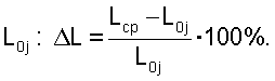
Потом усредняют эти значения на периоде и рассчитывают относительные отклонения полученных средних значений от образцовых величин, определенных на заведомо исправном трансформаторе. Далее сравнивают полученные отклонения с заранее заданной уставкой, и если хотя бы одно из этих отклонений больше заданной уставки, то делают вывод о неисправном состоянии соответствующей обмотки контролируемого трансформатора.Then, these values are averaged over the period and the relative deviations of the obtained average values from the standard values determined on a known-good transformer are calculated. Next, the obtained deviations are compared with a predetermined setpoint, and if at least one of these deviations is greater than the specified setpoint, then a conclusion is made about the malfunctioning state of the corresponding winding of the controlled transformer.
В рабочем режиме однофазного трансформатора Т, как показано на фиг.1, на первичную обмотку с числом витков W1 подают входное напряжение uвх(t), вторичная обмотка с числом витков W2 подключается к нагрузке Zн, а третья обмотка с числом витков W3 остается разомкнутой. При этом токи в первичной и вторичной обмотках i1(t) и i2(t) измеряют с помощью трансформаторов и датчиков тока, а напряжения на первичной, вторичной и третьей обмотках uвх(t), uн(t) и u3(t) измеряются с помощью трансформаторов и датчиков напряжения. Далее все перечисленные токи и напряжения через коммутатор подают на аналого-цифровой преобразователь.In the operating mode of a single-phase transformer T, as shown in figure 1, the input voltage u in (t) is supplied to the primary winding with the number of turns W 1 , the secondary winding with the number of turns W 2 is connected to the load Z n , and the third winding with the number of turns W 3 remains open. In this case, the currents in the primary and secondary windings i 1 (t) and i 2 (t) are measured using transformers and current sensors, and the voltage on the primary, secondary and third windings u in (t), u n (t) and u 3 (t) are measured using transformers and voltage sensors. Further, all of the listed currents and voltages are fed through a switch to an analog-to-digital converter.
Массив мгновенных значений тока вторичной обмотки приводят к первичной цепи по формулеAn array of instantaneous values of the secondary current leads to the primary circuit according to the formula
![]()
![]()
Массивы мгновенных значений напряжений на вторичной и третьей обмотках также приводят к первичной цепиArrays of instantaneous voltage values on the secondary and third windings also lead to the primary circuit
![]()
![]()
![]()
![]()
Все дальнейшие расчеты производят уже с массивами мгновенных значений указанных токов и напряжений, приведенных к первичной цепи.All further calculations are already done with arrays of instantaneous values of the indicated currents and voltages, reduced to the primary circuit.
В соответствии с Т-образной схемой замещения трансформатора в рабочем режиме (фиг.2) по второму закону Кирхгофа для массивов мгновенных значений рассчитываются падение напряжения на первом продольном сопротивлении схемы замещения u1(tj) и падение напряжения на втором продольном сопротивлении схемы замещения, приведенное к первичной цепи ![]()
![]()
![]()
![]()
![]()
![]()
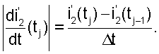
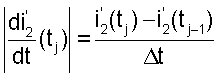
Далее производят дифференцирование массивов мгновенных значений токов первичной и приведенной вторичной ветвей |i1(tj)| и ![]()
![]()
![]()
![]()
Теперь для сопротивления первой продольной ветви, имеющего активную составляющую R1 и реактивную составляющую ωL1, где ω - циклическая частота напряжения, приложенного к первичной обмотке, a L1 - индуктивность рассеяния первичной обмотки трансформатора, мы имеем массивы мгновенных значений тока |i1(tj)|, производной тока ![]()
![]()
![]()
![]()
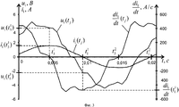
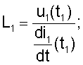
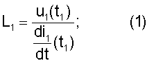
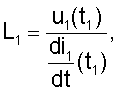
В этом уравнении два неизвестных R1 и L1. Уравнение записано для момента времени tj, поэтому мы имеем N таких уравнений на периоде. Так как для определения параметров R1 и L1 достаточно решить систему всего лишь из двух таких уравнений, выбираем моменты времени, в которых это сделать проще всего. А именно для определения индуктивности L1, решим уравнение (5) для момента времени t1, когда i1(tj)=0 (см. фиг.3), при этом уравнение (5) переходит в уравнение (1). А для определения сопротивления R1 решим уравнение (5) для момента времени t3, когда ![]()
![]()
Так как мы имеем дело с гармоническими сигналами, таких точек на периоде может быть не меньше, чем по две (на фиг.3 это моменты времени ![]()
![]()
![]()
![]()
![]()
![]()
![]()
![]()
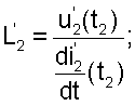
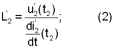
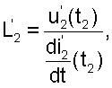
Аналогично для приведенного сопротивления второй продольной ветви, имеющего активную составляющую ![]()
![]()
![]()
![]()

![]()
![]()
![]()
![]()
![]()
![]()
![]()
![]()
В этом уравнении также два неизвестных: ![]()
![]()
![]()
![]()
![]()
![]()
![]()
![]()
![]()
![]()
![]()
![]()
Предлагаемый способ оперативного контроля позволяет определять значения индуктивностей рассеяния и активных сопротивлений обмоток трансформатора в рабочем режиме на каждом периоде тока и по отклонению этих параметров от образцовых значений, полученных на заведомо исправном трансформаторе, контролировать состояние обмоток трансформатора. За счет введения дополнительных контролируемых параметров - активных сопротивлений обмоток и независимого определения индуктивностей рассеяния первичной и вторичной обмоток, предлагаемый способ является более эффективным и надежным, чем прототип.The proposed method of operational control allows you to determine the values of the leakage inductances and active resistances of the transformer windings in the operating mode for each current period and by the deviation of these parameters from the reference values obtained on a known-good transformer, monitor the status of the transformer windings. Due to the introduction of additional controlled parameters - the active resistances of the windings and the independent determination of the leakage inductances of the primary and secondary windings, the proposed method is more efficient and reliable than the prototype.
На фиг.1 представлена схема измерений однофазного трансформатора с ненагруженной третьей обмоткой в рабочем режиме.Figure 1 presents the measurement circuit of a single-phase transformer with an unloaded third winding in operating mode.
На фиг.2 представлена Т-образная схема замещения однофазного трансформатора с ненагруженной третьей обмоткой в рабочем режиме.Figure 2 presents the T-shaped equivalent circuit of a single-phase transformer with an unloaded third winding in operating mode.
На фиг.3 представлены графические зависимости |u1(tj)|, |i1(tj)| и ![]()
![]()
На фиг.4 приведены графические зависимости ![]()
![]()

![]()
![]()
На фиг.5 представлена аппаратная схема устройства, реализующая рассматриваемый способ.Figure 5 presents the hardware circuit of the device that implements the considered method.
В табл.1 приведены исходные экспериментальные данные измерения токов и напряжений трансформатора ПОБС 5М в рабочем режиме и результаты промежуточных вычислений.Table 1 shows the initial experimental data on measuring the currents and voltages of the POBS 5M transformer in operating mode and the results of intermediate calculations.
В табл.2 приведены полученные значения индуктивностей рассеяния и активных сопротивлений обмоток трансформатора, образцовые значения этих параметров и их относительные отклонения от образцовых значений.Table 2 shows the obtained values of the scattering inductances and the active resistances of the transformer windings, exemplary values of these parameters and their relative deviations from the exemplary values.
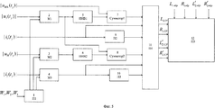
Способ может быть осуществлен с помощью схемы (фиг.5), содержащей программатор вычисления коэффициентов трансформации 1 (П1), масштабирующие блоки 2 (M1), 3 (М2), 4 (М3), инверторы 5 (ИНВ1) и 6 (ИНВ2), сумматоры 7 (Сумматор 1) и 9 (Сумматор 2), программаторы вычисления производных по времени 8 (П2) и 10 (П3), программатор вычисления индуктивности и активного сопротивления 11 (П4), программатор контроля 12 (П5).The method can be implemented using the circuit (figure 5), containing a programmer for calculating the transformation coefficients 1 (P1), scaling units 2 (M1), 3 (M2), 4 (M3), inverters 5 (INV1) and 6 (INV2) , adders 7 (Adder 1) and 9 (Adder 2), programmers for calculating the derivatives of time 8 (P2) and 10 (P3), a programmer for calculating the inductance and resistance 11 (P4), a control programmer 12 (P5).
Соответствующие входы сумматора 7 (Сумматор 1), масштабирующего блока 2 (M1), программатора вычисления индуктивности и активного сопротивления 11 (П4), программатора вычисления производных по времени 9 (П2), масштабирующих блоков 3 (М2) и 4 (М3) соединены с аналого-цифровыми преобразователями (не показаны на фиг.5). Входы программатора вычисления коэффициентов трансформации 1 (П1) и программатора контроля 12 (П5) соединены с кнопочной клавиатурой (не показана на фиг.5). Выходы программатора вычисления коэффициентов трансформации 1 (П1) соединены с соответствующими входами масштабирующих блоков 2 (M1), 3 (М2) и 4 (М3). Выход масштабирующего блока 2 (M1) соединен с входом инвертора 5 (ИНВ1) и с соответствующим входом сумматора 9 (Сумматор 2). Выход инвертора 5 (ИНВ1) соединен с соответствующим входом сумматора 7 (Сумматор 1). Выход сумматора 7 (Сумматор 1) соединен с соответствующим входом программатора вычисления индуктивности и активного сопротивления 11 (П4). Выход программатора вычисления производных по времени 8 (П2) соединен с соответствующим входом программатора вычисления индуктивности и активного сопротивления 11 (П4). Выход масштабирующего блока 3 (М2) соединен с входом инвертора 6 (ИНВ2). Выход инвертора 6 (ИНВ2) соединен с соответствующим входом сумматора 9 (Сумматор 2). Выход сумматора 9 (Сумматор 2) соединен с соответствующим входом программатора вычисления индуктивности и активного сопротивления 11 (П4). Выход масштабирующего блока 4 (М3) соединен с входом программатора вычисления производных по времени 10 (П3) и соответствующим входом программатора вычисления индуктивности и активного сопротивления 11 (П4). Выход программатора вычисления производных по времени 10 (П3) соединен с соответствующим входом программатора вычисления индуктивности и активного сопротивления 11 (П4). Выходы программатора вычисления индуктивности и активного сопротивления 11 (П4) соединены с соответствующими входами программатора контроля 12 (П5).The corresponding inputs of the adder 7 (Adder 1), the scaling unit 2 (M1), the programmer for calculating the inductance and active resistance 11 (P4), the programmer for calculating the time derivatives 9 (P2), the scaling blocks 3 (M2) and 4 (M3) are connected to analog-to-digital converters (not shown in figure 5). The inputs of the programmer for calculating the transformation coefficients 1 (P1) and the control programmer 12 (P5) are connected to a button keyboard (not shown in FIG. 5). The outputs of the programmer for calculating the transformation coefficients 1 (P1) are connected to the corresponding inputs of the scaling units 2 (M1), 3 (M2) and 4 (M3). The output of the scaling unit 2 (M1) is connected to the input of the inverter 5 (INV1) and to the corresponding input of the adder 9 (Adder 2). The output of the inverter 5 (INV1) is connected to the corresponding input of the adder 7 (Adder 1). The output of the adder 7 (Adder 1) is connected to the corresponding input of the programmer for calculating the inductance and active resistance 11 (P4). The output of the programmer for calculating the derivatives with respect to time 8 (P2) is connected to the corresponding input of the programmer for calculating the inductance and active resistance 11 (P2). The output of the scaling unit 3 (M2) is connected to the input of the inverter 6 (INV2). The output of the inverter 6 (INV2) is connected to the corresponding input of the adder 9 (Adder 2). The output of the adder 9 (Adder 2) is connected to the corresponding input of the programmer for calculating the inductance and active resistance 11 (P4). The output of the scaling unit 4 (M3) is connected to the input of the time derivative programmer 10 (P3) and the corresponding input of the inductance and resistance calculator 11 (P4). The output of the programmer for calculating the derivatives with respect to time 10 (P3) is connected to the corresponding input of the programmer for calculating the inductance and active resistance 11 (P4). The outputs of the programmer for calculating the inductance and active resistance 11 (P4) are connected to the corresponding inputs of the control programmer 12 (P5).
Масштабирующие блоки 2 (M1), 3 (М2), 4 (М3), инверторы 5 (ИНВ1) и 6 (ИНВ2), сумматоры 7 (Сумматор 1) и 9 (Сумматор2), программаторы вычисления производных по времени 8 (П2) и 10 (П3), программатор вычисления индуктивности и активного сопротивления 11 (П4) и программатор контроля 12 (П5) могут быть выполнены на микроконтроллере серии 51 производителя atmel AT89S53.Scaling blocks 2 (M1), 3 (M2), 4 (M3), inverters 5 (INV1) and 6 (INV2), adders 7 (Adder 1) and 9 (Adder2), time derivative programmers 8 (P2) and 10 (P3), a programmer for calculating the inductance and active resistance 11 (P4) and a control programmer 12 (P5) can be performed on a microcontroller of the 51 series atmel AT89S53.
В качестве примера приведен способ оперативного контроля состояния обмоток однофазного трансформатора ПОБС-5М с ненагруженной обмоткой в рабочем режиме при частоте f=50 Гц, количеством витков первичной обмотки W1=380, количеством витков вторичной обмотки W2=62 и количеством витков в третьей обмотке W3=12. Дискретность массивов мгновенных значений входного тока |i1(tj)|, входного напряжения |uвх(tj)|, выходного тока |i2(tj)|, выходного напряжения |uн(tj)|, напряжения на третьей обмотке |u3(tj)|-Δt=0,000625 с.As an example, a method for the operational monitoring of the state of the windings of a single-phase transformer POBS-5M with an unloaded winding in the operating mode at a frequency f = 50 Hz, the number of turns of the primary winding W 1 = 380, the number of turns of the secondary winding W 2 = 62 and the number of turns in the third winding is given W 3 = 12. Discreteness of arrays of instantaneous values of input current | i 1 (t j ) |, input voltage | u in (t j ) |, output current | i 2 (t j ) |, output voltage | u n (t j ) |, voltage third winding | u 3 (t j ) | -Δt = 0.000625 s.
При работе трансформатора в режиме, близком к номинальному, в соответствии со схемой измерений фиг.1 через измерительные преобразователи и аналого-цифровые преобразователи (не показаны) на входы соответствующих блоков, как показано на фиг.5, подают массивы мгновенных значений токов и напряжений во всех обмотках uвх(tj), u3(tj), i1(tj), uн(tj), i2(tj), приведенные в табл.1. В программатор вычисления коэффициентов трансформации 1 (П1) вводят значения чисел витков в обмотках трансформатора W1, W2, W3. В программатор контроля 12 (П5) вводят образцовые значения активных сопротивлений R1обр и R2обр и индуктивности рассеяния обмоток L1обр, и L2обр, определенные на заведомо исправном трансформаторе, показанные в табл.2.When the transformer is operating in a mode close to nominal, in accordance with the measurement scheme of FIG. 1, arrays of instantaneous values of currents and voltages are supplied to the inputs of the corresponding blocks through measuring transducers and analog-to-digital converters (not shown), as shown in FIG. 5 all windings u in (t j ), u 3 (t j ), i 1 (t j ), u n (t j ), i 2 (t j ), are given in Table 1. In the programmer for calculating the transformation coefficients 1 (P1), enter the values of the number of turns in the transformer windings W 1 , W 2 , W 3 . In the control programmer 12 (P5), exemplary values of the active resistances R 1 obr and R 2 obr and the dissipation inductance of the windings L 1 obr and L 2 obr determined on a known-good transformer are shown in Table 2.
С выхода масштабирующего блока 2 (M1) массив мгновенных значений напряжения на третьей обмотке ![]()
![]()
![]()
![]()
![]()
![]()
![]()
![]()
![]()
![]()
![]()
![]()
![]()
![]()
![]()
![]()
![]()
![]()
С выхода масштабирующего блока 3 (М2) массив мгновенных значений выходного напряжения ![]()
![]()
![]()
![]()
![]()
![]()
![]()
![]()

![]()
![]()
![]()
![]()
![]()
![]()
![]()
![]()
![]()
![]()
![]()
![]()
![]()
![]()
![]()
![]()
![]()
![]()
![]()
![]()
![]()
![]()
![]()
![]()
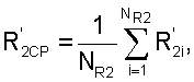
Затем значения L1CР, R1CP, ![]()
![]()
![]()
![]()


Результаты вычисления относительных отклонений приведены в табл.2. Далее в программаторе 12 (П5) относительные отклонения ΔL1, ΔR1, ![]()
![]()
![]()
![]()
![]()
![]()
![]()
![]()
СПОСОБ ОПЕРАТИВНОГО КОНТРОЛЯ СОСТОЯНИЯ ОБМОТОК ОДНОФАЗНОГО ТРАНСФОРМАТОРА С НЕНАГРУЖЕННОЙ ОБМОТКОЙTable 1
METHOD FOR OPERATIONAL MONITORING THE STATE OF WINDING OF SINGLE-PHASE TRANSFORMER WITH UNLOADED WINDING
![]()
![]()
![]()
![]()
![]()
![]()
![]()
![]()
![]()
![]()
![]()
![]()
СПОСОБ ОПЕРАТИВНОГО КОНТРОЛЯ СОСТОЯНИЯ ОБМОТОК ОДНОФАЗНОГО ТРАНСФОРМАТОРА С НЕНАГРУЖЕННОЙ ОБМОТКОЙTable 1 (continued)
METHOD FOR OPERATIONAL MONITORING THE STATE OF WINDING OF SINGLE-PHASE TRANSFORMER WITH UNLOADED WINDING


Claims (1)


Priority Applications (1)
| Application Number | Priority Date | Filing Date | Title |
|---|---|---|---|
| RU2007122925/28A RU2333503C1 (en) | 2007-06-18 | 2007-06-18 | Single-phase unloaded-winding transformer state on-line control method |
Applications Claiming Priority (1)
| Application Number | Priority Date | Filing Date | Title |
|---|---|---|---|
| RU2007122925/28A RU2333503C1 (en) | 2007-06-18 | 2007-06-18 | Single-phase unloaded-winding transformer state on-line control method |
Publications (1)
| Publication Number | Publication Date |
|---|---|
| RU2333503C1 true RU2333503C1 (en) | 2008-09-10 |
Family
ID=39867025
Family Applications (1)
| Application Number | Title | Priority Date | Filing Date |
|---|---|---|---|
| RU2007122925/28A RU2333503C1 (en) | 2007-06-18 | 2007-06-18 | Single-phase unloaded-winding transformer state on-line control method |
Country Status (1)
| Country | Link |
|---|---|
| RU (1) | RU2333503C1 (en) |
Cited By (2)
| Publication number | Priority date | Publication date | Assignee | Title |
|---|---|---|---|---|
| RU2469342C1 (en) * | 2008-09-24 | 2012-12-10 | Абб Рисерч Лтд | Method and apparatus for controlling secondary circuit measuring transformer in electric power system |
| RU2685571C1 (en) * | 2018-02-20 | 2019-04-22 | Федеральное государственное казённое военное образовательное учреждение высшего образования "Военная академия материально-технического обеспечения имени генерала армии А.В. Хрулева" Министерства обороны Российской Федерации | Device for measuring leakage inductances of individual windings of a two-winding transformer |
Citations (4)
| Publication number | Priority date | Publication date | Assignee | Title |
|---|---|---|---|---|
| SU1377779A1 (en) * | 1986-03-31 | 1988-02-28 | Научно-Исследовательский Центр По Испытанию Высоковольтной Аппаратуры | Method of testing transformer windings for mechanical deformation and turn-to-turn short circuits |
| RU2136099C1 (en) * | 1994-10-06 | 1999-08-27 | Учебно-научно-производственный комплекс УНПК "Энергия" | Device for checking and protecting transformer windings against deformation under short-circuit conditions |
| RU2240571C1 (en) * | 2003-04-02 | 2004-11-20 | Казанский государственный энергетический университет | Device for controlling technical condition of transformer windings |
| US7034547B2 (en) * | 2002-12-10 | 2006-04-25 | Alstom T&D Sa | Method of diagnosing a fault on a transformer winding |
-
2007
- 2007-06-18 RU RU2007122925/28A patent/RU2333503C1/en not_active IP Right Cessation
Patent Citations (4)
| Publication number | Priority date | Publication date | Assignee | Title |
|---|---|---|---|---|
| SU1377779A1 (en) * | 1986-03-31 | 1988-02-28 | Научно-Исследовательский Центр По Испытанию Высоковольтной Аппаратуры | Method of testing transformer windings for mechanical deformation and turn-to-turn short circuits |
| RU2136099C1 (en) * | 1994-10-06 | 1999-08-27 | Учебно-научно-производственный комплекс УНПК "Энергия" | Device for checking and protecting transformer windings against deformation under short-circuit conditions |
| US7034547B2 (en) * | 2002-12-10 | 2006-04-25 | Alstom T&D Sa | Method of diagnosing a fault on a transformer winding |
| RU2240571C1 (en) * | 2003-04-02 | 2004-11-20 | Казанский государственный энергетический университет | Device for controlling technical condition of transformer windings |
Cited By (2)
| Publication number | Priority date | Publication date | Assignee | Title |
|---|---|---|---|---|
| RU2469342C1 (en) * | 2008-09-24 | 2012-12-10 | Абб Рисерч Лтд | Method and apparatus for controlling secondary circuit measuring transformer in electric power system |
| RU2685571C1 (en) * | 2018-02-20 | 2019-04-22 | Федеральное государственное казённое военное образовательное учреждение высшего образования "Военная академия материально-технического обеспечения имени генерала армии А.В. Хрулева" Министерства обороны Российской Федерации | Device for measuring leakage inductances of individual windings of a two-winding transformer |
Similar Documents
| Publication | Publication Date | Title |
|---|---|---|
| EP2466322B1 (en) | Method and apparatus for transformer diagnosis | |
| KR101306397B1 (en) | Method for measuring the insulation resistance in an IT network | |
| CN101363895B (en) | Method and system for detecting DC circuit faults | |
| CN100549709C (en) | Calculation Method and Device of Circulating Current in Delta Winding of Y/△ Transformer | |
| EP2365348A2 (en) | Monitoring apparatus for current transformer | |
| CN104635014B (en) | Method and apparatus for increasing the current sense scope in multi-phase motor system | |
| KR20170131705A (en) | Method and apparatus for identifying phase-out of circuit breakers based on voltage | |
| CN102435858A (en) | On-line measurement method and system for transformer short-circuit loss and open-circuit loss | |
| CN109283399B (en) | Method for measuring loss of high-frequency magnetic element winding | |
| CA2496214A1 (en) | Testing of current transformers | |
| CN103630797B (en) | A kind of transformator turn-to-turn short circuit detection means | |
| CN106291123A (en) | A kind of method of direct measurement magnetic cell winding loss | |
| RU2333503C1 (en) | Single-phase unloaded-winding transformer state on-line control method | |
| Nistane et al. | Modeling, analysis, and online detection of interturn short-circuit fault in medium-frequency transformer of dual-active-bridge converter | |
| Dalala et al. | A current sensorless coulomb-counting method for enhanced battery state-of-charge estimation accuracy | |
| CN116794567A (en) | Digital twinning-based active distribution transformer abnormal state sensing method and system | |
| RU2003100586A (en) | DIAGNOSTIC METHOD FOR POWER TRANSFORMERS | |
| EP1482316A2 (en) | Current measurement in electrical machines | |
| RU2364876C1 (en) | Method to determine parametres of three-phase three-winding transformer equivalent t-circuit in operating conditions | |
| JPH11304870A (en) | Method for confirming polarity of tertiary winding of meter current transformer, and testing method for ground protective relay using the same | |
| RU2390035C1 (en) | Method for control of technical condition of single-phase and three-phase double-winding transformers in working mode | |
| JP2011155749A (en) | Testing device of cable run in distribution board | |
| CN117518062A (en) | Current transformer secondary circuit status inspection circuit and status inspection method | |
| RU2282862C1 (en) | Device for measuring current and open-circuit loss of power transformers at low voltage | |
| CN108732450A (en) | Short-circuit detecting system and method between high-power transformer rewinding material piece |
Legal Events
| Date | Code | Title | Description |
|---|---|---|---|
| MM4A | The patent is invalid due to non-payment of fees |
Effective date: 20090619 |