RU2317373C1 - Method for bored pile erection in ground - Google Patents
Method for bored pile erection in ground Download PDFInfo
- Publication number
- RU2317373C1 RU2317373C1 RU2007103316/03A RU2007103316A RU2317373C1 RU 2317373 C1 RU2317373 C1 RU 2317373C1 RU 2007103316/03 A RU2007103316/03 A RU 2007103316/03A RU 2007103316 A RU2007103316 A RU 2007103316A RU 2317373 C1 RU2317373 C1 RU 2317373C1
- Authority
- RU
- Russia
- Prior art keywords
- hole
- well
- soil
- drill
- pilot
- Prior art date
Links
Images
Landscapes
- Piles And Underground Anchors (AREA)
Abstract
Description
Изобретение относится к области промышленного и гражданского строительства и может быть использовано как при возведении новых, так и при усилении фундаментов ранее возведенных зданий и сооружений, а также при сооружении опор, воспринимающих знакопеременные нагрузки.The invention relates to the field of industrial and civil construction and can be used both in the construction of new and in the strengthening of the foundations of previously constructed buildings and structures, as well as in the construction of poles that accept alternating loads.
Известна винтовая свая, состоящая из ствола с винтовой нарезкой по всей его длине, с коническим сбегом у острия, снабженная расположенной и закрепленной на поверхности грунта гайкой, через которую пропущен ствол сваи, при этом угол подъема витков нарезки ствола и гайки α≥arctg f, где f - коэффициент трения материала гайки и сваи (SU, №727750, опубл. 15.04.1980).Known screw pile, consisting of a barrel with a screw thread along its entire length, with a tapered run at the tip, equipped with a nut located and fixed on the soil surface, through which the pile shaft is passed, while the angle of elevation of the turns of the trunk and nut α≥arctg f, where f is the coefficient of friction of the material of the nut and piles (SU, No. 727750, publ. 15.04.1980).
Недостатком данной сваи является необходимость использования для ее закручивания в грунт оборудования большой мощности, т.к. при завинчивании необходимо преодолевать не только силу трения со стороны грунта о поверхность сваи, но и аналогичную силу со стороны гайки, которую к тому же необходимо как-то закреплять на поверхности грунта, на что требуются дополнительные затраты времени и средств.The disadvantage of this pile is the need to use high power equipment for its twisting into the ground, because when tightening, it is necessary to overcome not only the friction force from the soil on the pile surface, but also the similar force from the nut side, which also needs to be somehow fixed on the soil surface, which requires additional time and money.
Наиболее близким по технической сути и достигаемому результату является способ возведения буронабивной сваи, включающий образование пилотной скважины в грунте путем бурения и выдачи разрушенного грунта на поверхность посредством полого шнекового бурового снаряда с породоразрушающим инструментом, извлечение его из скважины, размещение металлического каркаса и заполнение скважины бетоном (RU №2208088, кл. Е02D 5/56, опублик. 10.07.2003).The closest in technical essence and the achieved result is a method of constructing a bored pile, including the formation of a pilot well in the soil by drilling and issuing the destroyed soil to the surface by means of a hollow screw drill with a rock cutting tool, removing it from the well, placing a metal frame and filling the well with concrete ( RU No. 2208088, class E02D 5/56, published on July 10, 2003).
Данный способ возведения буронабивной сваи имеет ряд существенных недостатков. Завинчивание под давлением обсадной трубы с винтовой навивкой из арматуры круглого сечения по всей длине трубы (шнековая спираль) и с коническим разрыхлителем в грунты, даже со средней несущей способностью, требует применения тяжелых буровых установок большой мощности со значительным крутящим моментом, что не всегда возможно вблизи существующих фундаментов из-за их больших габаритов. Тот факт, что обсадная труба, заполненная бетонной смесью, остается в грунте в качестве сваи, слишком удорожает строительство фундамента. В случае вывинчивания обсадной трубы с винтовой навивкой по всей длине трубы требуется создание на вращателе буровой установки определенной скорости вращения и подачи вверх исходя из шага шнековой спирали, что практически невозможно сделать без нарушения стенок винтовой скважины. Наличие на обсадной трубе шнековой спирали с различным шагом вообще исключает образование винтовой нарезки в стенках скважины при вывинчивании обсадной трубы.This method of construction of a bored pile has a number of significant disadvantages. Pressure tightening of the casing with screw winding from round reinforcement along the entire length of the pipe (screw spiral) and with a conical baking powder into the soil, even with medium bearing capacity, requires the use of heavy drilling rigs of high power with significant torque, which is not always possible near existing foundations due to their large dimensions. The fact that the casing filled with concrete remains in the ground as piles makes the construction of the foundation too expensive. In case of unscrewing the casing with screw winding along the entire length of the pipe, it is necessary to create a certain rotation speed and feed rate on the rotator of the drilling rig based on the pitch of the screw spiral, which is almost impossible to do without breaking the walls of the screw well. The presence of a screw spiral on the casing with a different pitch generally eliminates the formation of helical threading in the borehole walls when the casing is unscrewed.
Техническим результатом, ожидаемым от использования данного изобретения, является повышение несущей способности буронабивной винтовой сваи и расширение области применения путем обеспечения использования при строительстве фундаментов в любых грунтовых условиях.The technical result expected from the use of this invention is to increase the bearing capacity of a bored screw pile and expand the scope by ensuring the use in the construction of foundations in any soil conditions.
Указанный технический результат достигается тем, что в способе возведения буронабивной винтовой сваи, включающем образование пилотной скважины в грунте путем бурения и выдачи разрушенного грунта на поверхность посредством полого шнекового бурового снаряда с породоразрушающим инструментом, извлечение его из скважины, размещение в скважине металлического каркаса и заполнение ее бетоном в стенках пилотной скважины выполняют винтовую щель, а подачу бетонной смеси осуществляют через внутренний канал шнекового бурового снаряда для заполнения образовавшейся в пилотной скважине полости и винтовой щели по мере поднятия бурового снаряда, а размещение в скважине металлического каркаса осуществляют после полного выхода бурового снаряда из скважины и заполнения ее бетонной смесью.The specified technical result is achieved by the fact that in the method of constructing a bored screw pile, including the formation of a pilot well in the soil by drilling and issuing the destroyed soil to the surface by means of a hollow auger drill with a rock cutting tool, removing it from the well, placing a metal frame in the well and filling it a helical gap is made in the walls of the pilot well with concrete, and the concrete mixture is supplied through the internal channel of the auger drill for filling neniya pilot hole formed in the cavity and the screw slot as the raising of the drill and placement of downhole metal frame is carried out after the complete release of the drill hole and filling it with concrete mix.
Указанный технический результат достигается и тем, что шнековый буровой снаряд снабжают устройством с выдвижным ножом и путем одновременного вращательного и поступательного вверх движений бурового снаряда с внедренным в стенку скважины выдвижным ножом образуют винтовую щель.The specified technical result is achieved by the fact that the auger drill is equipped with a retractable knife and, by simultaneous rotational and translational upward movements of the drill with a retractable knife embedded in the borehole wall, form a helical gap.
И тем, что в устойчивых и средней устойчивости грунтах образуют винтовую щели с равным шагом спирали по всей длине пилотной скважины без дополнительного уплотнения грунта стенок и подошвы винтовой щели.And the fact that in stable and moderate soils they form a helical gap with equal helix pitch along the entire length of the pilot well without additional soil compaction of the walls and the bottom of the helical gap.
А также тем, что в слабоустойчивых грунтах образуют винтовую щель с равным шагом спирали по всей длине пилотной скважины с дополнительным уплотнением грунта стенок и подошвы винтовой щели.And also by the fact that in weakly stable soils they form a helical gap with an equal helix pitch along the entire length of the pilot well with additional soil compaction of the walls and the bottom of the helical gap.
И тем, что в грунтах с перемежающейся степенью устойчивости по длине скважины обеспечивают возможность образования винтовой щели с переменным шагом спирали в зависимости от степени устойчивости грунтовых прослоек.And the fact that in soils with an alternating degree of stability along the length of the borehole provide the possibility of the formation of a helical gap with a variable spiral pitch, depending on the degree of stability of the soil layers.
Указанные признаки являются существенными и достаточными для получения требуемого технического результата.These signs are essential and sufficient to obtain the desired technical result.
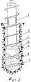
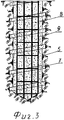
Изобретение поясняется чертежами, где на фиг.1 схематично изображена пустотелая шнековая бурильная колонна с породоразрушающим инструментом и устройством с выдвижным ножом для образования винтовой щели, находящимися ниже проектной глубины пилотной скважины, на фиг.2 - та же бурильная колонна с выдвинутым ножом в процессе образования винтовой щели в стенках пилотной скважины, на фиг.3 - готовая винтовая свая.The invention is illustrated by drawings, in which Fig. 1 schematically shows a hollow auger drill string with a rock cutting tool and a device with a retractable knife for forming a helical gap below the design depth of the pilot well, and Fig. 2 shows the same drill string with an extended knife in the process of formation helical gap in the walls of the pilot well, figure 3 - finished screw pile.
Способ осуществляется следующим образом.The method is as follows.
На поверхности грунта собирают буровой снаряд, состоящий из полой шнековой колонны 1, верхний конец которой выполнен с элементом связи 2 с вращателем буровой установки (на фиг.1 не показан), обеспечивающий передачу крутящего момента и осевого усилия на породоразрушающий инструмент 3 и устройство 4 с выдвижным ножом 6 для образования винтовой щели 7 в стенках пилотной скважины 5. Данным буровым снарядом проходят пилотную скважину 5 ниже проектной глубины будущей винтовой сваи на величину, равную высоте породоразрушающего инструмента 3 и устройства 4.A drill consisting of a hollow screw column 1 is assembled on the soil surface, the upper end of which is made with a coupling element 2 with a drill rig rotator (not shown in FIG. 1), which provides transmission of torque and axial force to the
Затем под давлением подают бетонную смесь 8 (см. фиг.2) по внутреннему каналу полой шнековой колонны 1 к забою пилотной скважины 5. Под действием давления бетонной смеси в устройстве 4 срабатывает механизм выдвижения (не показан) винтообразующего выдвижного ножа 6, который внедряется в стенку пилотной скважины 5. После этого, не прекращая подачи бетонной смеси 8, начинают вращать полую шнековую колонну 1 с одновременной подачей ее вверх с определенной равномерной скоростью вращения и подачей бурового снаряда. Внедрившийся в грунт выдвижной нож 6 под действием крутящего момента и тангенциального усилия разрушает его, образовывая винтовую щель 7 в стенках пилотной скважины 5. Ширина образованной винтовой щели 7 равна ширине выдвижного ножа 6, а глубина равна величине выхода выдвижного ножа 6 за пределы диаметра пилотной скважины. Шаг спирали винтовой щели заранее задан и зависит от степени устойчивости грунта. Затем в образовавшуюся полость и винтовую щель продолжают нагнетать бетонную смесь до полного заполнения.Then, under pressure, concrete mixture 8 (see FIG. 2) is fed through the internal channel of the hollow screw column 1 to the face of the pilot well 5. Under the action of the concrete mixture pressure in the device 4, the extension mechanism (not shown) of the screw-forming
При возведении сваи в перемежающихся по устойчивости грунтах переменный шаг спирали винтовой щели 7 обеспечивают изменением скорости вращения и подачи вверх бурового шнекового снаряда.When erecting piles in alternating in stability soils, a variable helix pitch of the
После полного вывода из пилотной скважины 5 полого шнекового бурового снаряда и заполнения пилотной скважины 5, имеющей уже вид винтовой скважины, бетонной смесью 8 (см. фиг.3) до ее затвердения в ствол скважины опускают металлический каркас 9. После полного затвердения бетонной смеси буронабивная винтовая свая готова к эксплуатации.After the hollow auger drill string is completely withdrawn from the pilot well 5 and the pilot well 5, which already has the appearance of a helical well, is filled with concrete mixture 8 (see FIG. 3), the metal frame 9 is lowered into the wellbore until it hardens. After the concrete mixture has completely hardened, the bored hole screw pile is ready for use.
Таким образом, способ возведения буронабивной винтовой сваи по изобретению обладает следующими преимуществами по сравнению с известными.Thus, the method of construction of a bored screw pile according to the invention has the following advantages compared with the known.
1. Отпадает необходимость использования тяжелого и энергоемкого бурового оборудования, имеющего, как правило, большие габариты, что зачастую оказывается неприемлемым в стесненных условиях существующих строений.1. There is no need to use heavy and energy-intensive drilling equipment, which, as a rule, has large dimensions, which is often unacceptable in the cramped conditions of existing buildings.
2. Исключается необходимость обеспечения синхронности вращения и подачи вверх при вывинчивании шнековой колонны исходя из шага спирали.2. Eliminates the need for synchronization of rotation and feed up when unscrewing the screw columns based on the pitch of the spiral.
3. Обеспечивается возможность возведения буронабивных винтовых свай в непосредственной близости от фундаментов реконструируемых зданий и сооружений без воздействия на грунт ударов и вибрации, нарушающих и ослабляющих окружающий сваю грунт.3. It is possible to erect bored screw piles in the immediate vicinity of the foundations of reconstructed buildings and structures without impacting the ground with shocks and vibrations that violate and weaken the surrounding soil.
4. Обеспечивается возможность возведения винтовых свай с различным, равным по всей длине сваи шагом винтовой спирали в зависимости от степени устойчивости грунта, а в грунтах с перемежающейся степенью устойчивости возведение свай с изменяющимся по длине сваи шагом винтовой спирали.4. It is possible to erect piles with different pitch of a helical spiral along the entire length of the pile, depending on the degree of soil stability, and in soils with an alternating degree of stability, erect piles with a pitch of a spiral spiral varying along the length of the pile.
5. Обеспечивается высокая производительность возведения буронабивных винтовых свай в широком диапазоне степени устойчивости грунтов.5. Provides high performance construction of bored screw piles in a wide range of soil stability.
Claims (5)
Priority Applications (1)
| Application Number | Priority Date | Filing Date | Title |
|---|---|---|---|
| RU2007103316/03A RU2317373C1 (en) | 2007-01-30 | 2007-01-30 | Method for bored pile erection in ground |
Applications Claiming Priority (1)
| Application Number | Priority Date | Filing Date | Title |
|---|---|---|---|
| RU2007103316/03A RU2317373C1 (en) | 2007-01-30 | 2007-01-30 | Method for bored pile erection in ground |
Publications (1)
| Publication Number | Publication Date |
|---|---|
| RU2317373C1 true RU2317373C1 (en) | 2008-02-20 |
Family
ID=39267227
Family Applications (1)
| Application Number | Title | Priority Date | Filing Date |
|---|---|---|---|
| RU2007103316/03A RU2317373C1 (en) | 2007-01-30 | 2007-01-30 | Method for bored pile erection in ground |
Country Status (1)
| Country | Link |
|---|---|
| RU (1) | RU2317373C1 (en) |
Cited By (2)
| Publication number | Priority date | Publication date | Assignee | Title |
|---|---|---|---|---|
| RU195719U1 (en) * | 2019-11-21 | 2020-02-04 | Федеральное государственное бюджетное образовательное учреждение высшего образования "Новосибирский государственный архитектурно-строительный университет (Сибстрин)" | Device for the formation of bored piles screw profile |
| RU2717554C1 (en) * | 2019-11-28 | 2020-03-24 | Федеральное государственное автономное образовательное учреждение высшего образования "Сибирский федеральный университет" | Bored pile device method |
Citations (6)
| Publication number | Priority date | Publication date | Assignee | Title |
|---|---|---|---|---|
| US4405262A (en) * | 1980-01-08 | 1983-09-20 | Masaya Nagashima | Method for erection of a temporary bridge, and a pile means therefor |
| EP0228138A2 (en) * | 1985-12-31 | 1987-07-08 | Gaspar Jozef Coelus | Process for placing a concrete pile in the ground and a screw drill and casing to be used in the process |
| RU2139978C1 (en) * | 1998-12-28 | 1999-10-20 | Гречный Борис Владимирович | Plant for concreting cast-in-place piles |
| RU2208088C2 (en) * | 2001-08-28 | 2003-07-10 | Басиев Асхар Николаевич | Process of erection of pile in ground |
| RU2208089C2 (en) * | 2001-08-28 | 2003-07-10 | Басиев Асхар Николаевич | Process of erection of pile in ground |
| RU2270294C1 (en) * | 2004-09-08 | 2006-02-20 | Ахсар Николаевич Басиев | Bored pile and method for pile erection in karst or soft ground |
-
2007
- 2007-01-30 RU RU2007103316/03A patent/RU2317373C1/en not_active IP Right Cessation
Patent Citations (6)
| Publication number | Priority date | Publication date | Assignee | Title |
|---|---|---|---|---|
| US4405262A (en) * | 1980-01-08 | 1983-09-20 | Masaya Nagashima | Method for erection of a temporary bridge, and a pile means therefor |
| EP0228138A2 (en) * | 1985-12-31 | 1987-07-08 | Gaspar Jozef Coelus | Process for placing a concrete pile in the ground and a screw drill and casing to be used in the process |
| RU2139978C1 (en) * | 1998-12-28 | 1999-10-20 | Гречный Борис Владимирович | Plant for concreting cast-in-place piles |
| RU2208088C2 (en) * | 2001-08-28 | 2003-07-10 | Басиев Асхар Николаевич | Process of erection of pile in ground |
| RU2208089C2 (en) * | 2001-08-28 | 2003-07-10 | Басиев Асхар Николаевич | Process of erection of pile in ground |
| RU2270294C1 (en) * | 2004-09-08 | 2006-02-20 | Ахсар Николаевич Басиев | Bored pile and method for pile erection in karst or soft ground |
Cited By (2)
| Publication number | Priority date | Publication date | Assignee | Title |
|---|---|---|---|---|
| RU195719U1 (en) * | 2019-11-21 | 2020-02-04 | Федеральное государственное бюджетное образовательное учреждение высшего образования "Новосибирский государственный архитектурно-строительный университет (Сибстрин)" | Device for the formation of bored piles screw profile |
| RU2717554C1 (en) * | 2019-11-28 | 2020-03-24 | Федеральное государственное автономное образовательное учреждение высшего образования "Сибирский федеральный университет" | Bored pile device method |
Similar Documents
| Publication | Publication Date | Title |
|---|---|---|
| EP3953529B1 (en) | Construction method and device for execution of a cast in-situ pile with multiple diameters decreasing with depth | |
| KR930012067B1 (en) | Soil treatment and continuous installation method of multiple equipments and devices | |
| JP5658988B2 (en) | Soil cement steel pipe composite pile and its construction method | |
| US3422629A (en) | Construction support system and methods and apparatus for construction thereof | |
| US6283231B1 (en) | Soil displacing screw auger and method for making a concrete pile with this auger | |
| CN102162248B (en) | Method for forming variable-cross-section compaction thread pile and compaction drilling tool | |
| CN103806840A (en) | One-way spiral half soil compaction drill bit and one-way spiral half soil compaction pile construction technology | |
| CN102619224B (en) | Construction method and drilling tool for variable cross-section bored cast-in-place pile (rock bolt) | |
| CN106192996A (en) | The construction method of a kind of T-shaped stake and the T-shaped drilling tool of T-shaped cast pile driving construction | |
| CN112252308A (en) | Concrete cast-in-place pile with enlarged diameter screw thread pile section, drill bit device for pile formation, and pile formation method | |
| US6120214A (en) | Process for constructing reinforced subterranean columns | |
| CN213709498U (en) | Concrete cast-in-place pile with enlarged diameter screw thread pile section and drill bit device for forming piles | |
| EP1158104A1 (en) | Pile formation | |
| RU2317373C1 (en) | Method for bored pile erection in ground | |
| JP5034581B2 (en) | Underground structure construction method and underground structure constructed by the method | |
| RU2354781C2 (en) | Method of bored pile construction and device for method implementation | |
| JP2015212485A (en) | Ground reinforcement method using steel pipe pile and consolidation tool for use in the same | |
| CN108374411A (en) | The dismountable screw pile machine of ultra-deep pile foundation drilling rod and the construction method of ultra-deep stake | |
| RU2717554C1 (en) | Bored pile device method | |
| RU2208088C2 (en) | Process of erection of pile in ground | |
| RU2328575C1 (en) | Bored auger pile installation device | |
| CN211523297U (en) | Prefabricated self-drilling screw anti-floating anchor rod | |
| RU2439247C2 (en) | Device for erection of bored screw piles | |
| JP4867731B2 (en) | Underground structure construction method, underground structure constructed by the method, and tubular member | |
| KR101024257B1 (en) | Earth anchor construction method and device for reinforcing soft ground |
Legal Events
| Date | Code | Title | Description |
|---|---|---|---|
| MM4A | The patent is invalid due to non-payment of fees |
Effective date: 20120131 |