RU2316652C2 - Turbine blade shroud mounting method - Google Patents
Turbine blade shroud mounting method Download PDFInfo
- Publication number
- RU2316652C2 RU2316652C2 RU2003116163/06A RU2003116163A RU2316652C2 RU 2316652 C2 RU2316652 C2 RU 2316652C2 RU 2003116163/06 A RU2003116163/06 A RU 2003116163/06A RU 2003116163 A RU2003116163 A RU 2003116163A RU 2316652 C2 RU2316652 C2 RU 2316652C2
- Authority
- RU
- Russia
- Prior art keywords
- blades
- elements
- bandage
- spikes
- shroud
- Prior art date
Links
Images
Classifications
-
- F—MECHANICAL ENGINEERING; LIGHTING; HEATING; WEAPONS; BLASTING
- F01—MACHINES OR ENGINES IN GENERAL; ENGINE PLANTS IN GENERAL; STEAM ENGINES
- F01D—NON-POSITIVE DISPLACEMENT MACHINES OR ENGINES, e.g. STEAM TURBINES
- F01D5/00—Blades; Blade-carrying members; Heating, heat-insulating, cooling or antivibration means on the blades or the members
- F01D5/30—Fixing blades to rotors; Blade roots ; Blade spacers
- F01D5/32—Locking, e.g. by final locking blades or keys
-
- F—MECHANICAL ENGINEERING; LIGHTING; HEATING; WEAPONS; BLASTING
- F01—MACHINES OR ENGINES IN GENERAL; ENGINE PLANTS IN GENERAL; STEAM ENGINES
- F01D—NON-POSITIVE DISPLACEMENT MACHINES OR ENGINES, e.g. STEAM TURBINES
- F01D5/00—Blades; Blade-carrying members; Heating, heat-insulating, cooling or antivibration means on the blades or the members
- F01D5/12—Blades
- F01D5/22—Blade-to-blade connections, e.g. for damping vibrations
- F01D5/225—Blade-to-blade connections, e.g. for damping vibrations by shrouding
-
- Y—GENERAL TAGGING OF NEW TECHNOLOGICAL DEVELOPMENTS; GENERAL TAGGING OF CROSS-SECTIONAL TECHNOLOGIES SPANNING OVER SEVERAL SECTIONS OF THE IPC; TECHNICAL SUBJECTS COVERED BY FORMER USPC CROSS-REFERENCE ART COLLECTIONS [XRACs] AND DIGESTS
- Y10—TECHNICAL SUBJECTS COVERED BY FORMER USPC
- Y10T—TECHNICAL SUBJECTS COVERED BY FORMER US CLASSIFICATION
- Y10T29/00—Metal working
- Y10T29/49—Method of mechanical manufacture
- Y10T29/49316—Impeller making
- Y10T29/4932—Turbomachine making
- Y10T29/49321—Assembling individual fluid flow interacting members, e.g., blades, vanes, buckets, on rotary support member
Landscapes
- Engineering & Computer Science (AREA)
- Mechanical Engineering (AREA)
- General Engineering & Computer Science (AREA)
- Turbine Rotor Nozzle Sealing (AREA)
Abstract
Description
Настоящее изобретение относится к многослойному бандажу лопаток для турбин и, в частности, относится к многослойному бандажу лопаток, содержащему промежуточный слой, и способам его монтажа.The present invention relates to a multilayer band of blades for turbines and, in particular, relates to a multilayer band of blades containing an intermediate layer, and methods for its installation.
Обычно на рабочем колесе турбины (например, таком, как описано в SU 1430555, 1988, F01D 5/22, 3 с.) смонтирована совокупность аэродинамических поверхностей или лопаток, разнесенных по окружности и, в общем случае, ориентированных в радиальном направлении. Традиционно на концах лопаток укреплен бандаж, образующий вокруг лопаток замкнутое кольцо с малым зазором между наружной поверхностью бандажа и окружающим кожухом.Usually, a set of aerodynamic surfaces or vanes spaced around the circumference and generally oriented in the radial direction is mounted on the turbine impeller (for example, such as described in SU 1430555, 1988, F01D 5/22, 3 pp.). Traditionally, a band is fastened at the ends of the blades, forming a closed ring around the blades with a small gap between the outer surface of the band and the surrounding casing.
Известны несколько разных конструкций и способов крепления бандажа к концам лопаток. Одна из этих конструкций предусматривает расклепывание шипа поверх бандажа. Согласно этой конструкции один или несколько шипов, выступающих, в общем случае, в радиальном направлении от каждой лопатки, проходят через соответствующие отверстия в бандаже и подлежат расклепыванию, предпочтительно автоматическому, вдоль внешней поверхности бандажа. Эта конфигурация шипов, расклепанных поверх бандажа, обеспечивает значительную прочность на отрыв, т.е. достаточную прочность конструкции, образованной бандажом и лопаткой, чтобы препятствовать отрыву бандажа от конца лопатки под действием центробежных сил. Однако конфигурация шипов, расклепанных поверх бандажа, не обеспечивает надлежащего уплотнения бандажа. Дело в том, что в результате расклепывания вдоль внешней поверхности бандажа образуется ряд выступов в радиальном направлении, что неизбежно приводит к увеличению зазора между вращающейся деталью, т.е. бандажом, и окружающей неподвижной деталью, т.е. кожухом, из-за чего увеличиваются потери на концевую утечку. Однако конфигурация шипов, расклепанных поверх бандажа, имеет то преимущество, что позволяет осуществлять операцию расклепывания автоматически.Several different designs and methods for attaching the bandage to the ends of the blades are known. One of these designs involves cleaving the spike over the brace. According to this design, one or more spikes protruding, generally in the radial direction from each blade, pass through the corresponding holes in the band and are subject to riveting, preferably automatically, along the outer surface of the band. This configuration of studs riveted over the brace provides significant peel strength, i.e. sufficient strength of the structure formed by the bandage and the blade to prevent the separation of the bandage from the end of the blade under the action of centrifugal forces. However, the configuration of the studs riveted over the bandage does not provide a proper seal for the bandage. The fact is that as a result of riveting along the outer surface of the bandage, a series of protrusions are formed in the radial direction, which inevitably leads to an increase in the gap between the rotating part, i.e. bandage, and surrounding stationary part, i.e. casing, due to which the loss of end leakage increases. However, the configuration of the studs riveted over the brace has the advantage of allowing the riveting operation to be carried out automatically.
Согласно другой конфигурации, а именно шипов, расклепанных внутри бандажа, шип лопатки заглублен относительно наружного отверстия бандажа. Ввиду отсутствия клепок, выступающих над внешней поверхностью бандажа, «заглубленная» конфигурация позволяет уменьшить концевой зазор с окружающей неподвижной деталью, что повышает степень уплотнения бандажа и снижает потери на концевую утечку. Однако для применения конфигурации шипов, расклепанных внутри бандажа, процесс расклепывания для прикрепления бандажа к лопаткам требуется осуществлять вручную. Это физически трудоемкий и дорогостоящий процесс. Соответственно, необходима такая конструкция бандажа лопаток, которая, с одной стороны, обеспечивает достаточную прочность на отрыв, а с другой - допускает автоматизацию процесса расклепывания, что обеспечивает надлежащее уплотнение бандажа, позволяющее минимизировать потери на концевую утечку.According to another configuration, namely, the studs riveted inside the bandage, the spike of the blade is recessed relative to the outer opening of the bandage. Due to the absence of rivets protruding above the outer surface of the bandage, the “recessed” configuration allows to reduce the end gap with the surrounding stationary part, which increases the degree of compaction of the bandage and reduces the loss of end leakage. However, to apply the configuration of the studs riveted inside the brace, the riveting process for attaching the brace to the blades must be carried out manually. This is a physically laborious and expensive process. Accordingly, such a design of the bandage of the blades is necessary, which, on the one hand, provides sufficient peel strength, and on the other hand, allows the riveting process to be automated, which ensures proper sealing of the bandage, which minimizes the loss of end leakage.
Согласно предпочтительному варианту осуществления настоящего изобретения предусмотрен бандаж лопаток, выполненный из нескольких слоев или элементов дугообразной формы, охватывающих наружные концы лопаток. Бандаж лопаток предусмотрен в виде множественных дугообразных сегментов, образующих замкнутое кольцо по периметру ротора, причем каждый сегмент состоит из нескольких элементов. Предпочтительно каждый сегмент бандажа лопаток содержит внутренний элемент, наружный элемент и промежуточный элемент, находящийся между внутренним и наружным элементами. Сегменты, а следовательно, элементы, могут охватывать три или более лопаток и насажены на шипы лопаток.According to a preferred embodiment of the present invention, there is provided a bandage of blades made of several layers or elements of an arcuate shape, covering the outer ends of the blades. The bandage of the blades is provided in the form of multiple arcuate segments forming a closed ring around the perimeter of the rotor, and each segment consists of several elements. Preferably, each segment of the bandage of the blades contains an inner element, an outer element and an intermediate element located between the inner and outer elements. Segments, and therefore elements, can span three or more blades and are mounted on the spikes of the blades.
В частности, элементы снабжены разнесенными по окружности отверстиями, совпадающими друг с другом, в которые входят шипы, имеющиеся на концах лопаток. Очевидно, шипы имеют усеченный профиль по сравнению с профилем аэродинамической поверхности лопаток. Между усеченным профилем шипа на конце лопатки и профилем аэродинамической поверхности предусмотрен изгиб по радиусу или фаска. Каждое отверстие во внутреннем элементе снабжено фаской, обращенной к оси вращения ротора, для наложения на изогнутый по радиусу участок на стыке между шипом и аэродинамической поверхностью лопатки. Промежуточный элемент содержит отверстия, соответствующие профилю шипа. Наружный элемент имеет отверстия, снабженные фаской, обращенной от оси вращения ротора. Внутренний, промежуточный и наружный элементы размещают на лопатках последовательно, причем шипы проходят через отверстия. Для прикрепления элементов к лопаткам выступающие концы шипов можно расклепывать, предпочтительно делать это автоматически. Для обеспечения гладкой, непрерывной поверхности по окружности бандажа избыточный материал шипов полностью удаляют, например, методом машинной обработки. Это дает возможность обеспечивать узкий зазор между бандажом и окружающей неподвижной деталью.In particular, the elements are provided with circumferentially spaced holes coinciding with each other, which include the spikes available at the ends of the blades. Obviously, the spikes have a truncated profile compared to the profile of the aerodynamic surface of the blades. Between the truncated profile of the tenon at the end of the blade and the profile of the aerodynamic surface, a radius bend or chamfer is provided. Each hole in the inner element is equipped with a chamfer facing the axis of rotation of the rotor, for imposition on the radius-curved section at the junction between the spike and the aerodynamic surface of the blade. The intermediate element contains holes corresponding to the profile of the tenon. The outer element has openings provided with a chamfer facing away from the axis of rotation of the rotor. The inner, intermediate and outer elements are placed on the blades in series, with the spikes passing through the holes. To attach the elements to the blades, the protruding ends of the spikes can be riveted, preferably automatically. To ensure a smooth, continuous surface around the circumference of the bandage, the excess material of the studs is completely removed, for example, by machining. This makes it possible to provide a narrow gap between the bandage and the surrounding stationary part.
Для обеспечения необходимой прочности на отрыв в промежуточных элементах предусмотрены полости между соседними местами посадки на шипы. Полости представляют собой выемки в материале, закрытые боковыми стенками промежуточного элемента, обращенными к потоку горячего газа через турбину и от него, и ограничены наружной и внутренней поверхностями внутреннего и наружного элементов соответственно. Это позволяет значительно снизить вес бандажа, а следовательно, минимизировать центробежные силы, приводящие к радиальному смещению сегментов бандажа наружу, что дает возможность существенно снизить требования к прочности на отрыв. Элементы бандажа можно выравнивать друг с другом по радиусам, проходящим через соседние по окружности места стыковки, однако элементы можно также устанавливать по отношению друг к другу со сдвигом, в результате чего точки стыковки между соседними по окружности элементами оказываются невыровненными или сдвинутыми в круговом направлении по отношению друг к другу.To provide the necessary tensile strength in the intermediate elements, cavities are provided between adjacent places of landing on the spikes. The cavities are recesses in the material, closed by the side walls of the intermediate element, facing the flow of hot gas through and from the turbine, and bounded by the outer and inner surfaces of the inner and outer elements, respectively. This can significantly reduce the weight of the brace, and therefore, minimize centrifugal forces leading to a radial displacement of the segments of the brace outward, which makes it possible to significantly reduce the requirements for tensile strength. The elements of the bandage can be aligned with each other along radii passing through adjacent to the circumference of the docking points, however, the elements can also be set relative to each other with a shift, as a result of which the connection points between the neighboring circumferential elements are unaligned or shifted in a circular direction with respect to to each other.
Вышеописанная конструкция обеспечивает конфигурацию шипов, расклепанных заподлицо с бандажом, имеющую надлежащую прочность на отрыв, которая, предпочтительно, может быть выполнена с применением оборудования автоматического расклепывания. Вместе с тем за счет сужения зазоров между кольцом бандажа и окружающим кожухом улучшается уплотнение бандажа.The above construction provides the configuration of the studs riveted flush with the brace having the proper tensile strength, which, preferably, can be performed using automatic riveting equipment. However, by narrowing the gaps between the bandage ring and the surrounding casing, the sealage of the bandage is improved.
Также предусмотрен бандаж лопаток турбины, имеющий шип, примыкающий к концу лопатки, бандаж содержит отдельные внутренний и наружный дугообразные элементы бандажа и промежуточный дугообразный элемент бандажа между ними, причем элементы имеют, в общем случае, радиально выровненные отверстия для приема шипа лопатки, наружный элемент снабжен фаской, обращенной от оси ротора, для приема материала расклепанного шипа лопатки для удержания элементов на лопатке.A turbine blade bandage is also provided having a spike adjacent to the end of the blade, the bandage contains separate inner and outer arcuate band elements and an intermediate arcuate band element between them, the elements having generally radially aligned openings for receiving the blade spike, the outer element is provided a chamfer facing away from the axis of the rotor for receiving material of the riveted spike of the blade for holding the elements on the blade.
Согласно варианту осуществления настоящего изобретения предусмотрена вращающаяся деталь турбины, содержащая совокупность разнесенных по окружности лопаток, вращающихся вокруг оси и оканчивающихся шипами, выступающими радиально наружу, бандаж лопаток, содержащий совокупность отдельных дугообразных сегментов бандажа, причем каждый сегмент имеет внутренний, наружный и промежуточный дугообразные элементы, элементы имеют, в общем случае, радиально выровненные отверстия в разнесенных по окружности положениях вдоль сегментов для приема шипов, шипы расклепаны для крепления элементов на лопатках и формирования в целом гладкой, непрерывной наружной поверхности из наружной поверхности наружного элемента.According to an embodiment of the present invention, there is provided a rotating part of a turbine comprising a plurality of circumferentially spaced apart blades rotating around an axis and terminating in spikes protruding radially outwardly, a band of blades comprising a plurality of distinct arcuate segments of the bandage, each segment having an inner, outer and intermediate arcuate elements, the elements have generally radially aligned holes in circumferentially spaced positions along the segments for receiving spikes, spikes are riveted for attaching the elements to the blades and forming a generally smooth, continuous outer surface from the outer surface of the outer element.
Согласно предпочтительному варианту осуществления настоящего изобретения предусмотрен способ монтажа бандажа на лопатках вращающейся детали турбины, содержащий этапы, на которых обеспечивают внутренние, наружные и промежуточные дугообразные элементы бандажа, снабженные отверстиями для приема шипов, предусмотренных на концах лопаток, последовательно размещают внутренние, промежуточные и наружные элементы бандажа на шипах лопаток, причем концы шипов выступают из наружного элемента, расклепывают выступающие концы шипов для крепления элементов к лопаткам и обеспечивают гладкую непрерывную дугообразную поверхность вдоль наружной поверхности бандажа, в том числе вдоль расклепанных концов шипов.According to a preferred embodiment of the present invention, there is provided a method of mounting a brace on the blades of a rotating turbine part, comprising the steps of providing internal, external and intermediate arcuate brace elements provided with holes for receiving studs provided at the ends of the blades, and sequentially arranging the inner, intermediate and outer elements a bandage on the spikes of the blades, the ends of the spikes protruding from the outer element, unfasten the protruding ends of the spikes for fastening I elements to the shoulder blades and provide a smooth continuous arcuate surface along the outer surface of the brace, including along the riveted ends of the spikes.
Предпочтительно в промежуточном элементе формируют полость между его соседними отверстиями.Preferably, a cavity is formed in the intermediate member between its adjacent openings.
Предпочтительно в промежуточных элементах формируют сквозную полость между соседними отверстиями.Preferably, a through cavity is formed in the intermediate elements between adjacent openings.
Предпочтительно в промежуточных элементах формируют сквозную полость, причем полость ограничена внутренней и наружной поверхностями наружного и внутреннего элементов соответственно, противоположными по оси краевыми стенками промежуточного элемента и противоположными по окружности перегородками промежуточного элемента, образующими краевые стенки по отношению друг к другу.Preferably, a through cavity is formed in the intermediate elements, the cavity being bounded by the inner and outer surfaces of the outer and inner elements, respectively, axially opposite the edge walls of the intermediate element and opposite in circumference by the partitions of the intermediate element, forming edge walls with respect to each other.
Краткое описание чертежейBrief Description of the Drawings
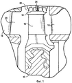
Фиг.1 - фрагментарный вид в разрезе части турбины, на котором показан ротор турбины с лопатками и бандажом и соответствующие каскады статора турбины.Figure 1 is a fragmentary sectional view of a part of the turbine, which shows the turbine rotor with blades and bandage and the corresponding cascades of the turbine stator.
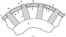
Фиг.2 - схематический фрагментарный вид в разрезе поперек оси, на котором показано наложение многослойного бандажа лопатки, отвечающего настоящему изобретению, на шипы лопаток ротора.Figure 2 is a schematic fragmentary cross-sectional view across the axis, which shows the superposition of the multilayer bandage of the blade of the present invention on the spikes of the rotor blades.
Фиг.3 - вид, аналогичный фиг.2, на котором показан бандаж лопаток в окончательном исполнении.Figure 3 is a view similar to figure 2, which shows the bandage of the blades in the final version.
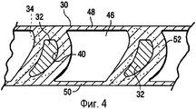
Фиг.4 - вид в разрезе примерно по линии 4-4 на фиг.3.FIG. 4 is a sectional view taken approximately along line 4-4 of FIG. 3.
На чертежах, в частности фиг.1, показан ротор 10, на котором смонтирована совокупность разнесенных по окружности лопаток, одна из них 12, и прикрепленный к ней бандаж 14. Показаны также соседние в осевом направлении лопатки 16 и 18 статора, относящиеся к неподвижным деталям турбины, образующие поточный канал 20 турбины. Показаны также уплотнитель 22 лабиринтного типа, а также щеточный уплотнитель 24, обеспечивающие уплотнение вокруг бандажа 14 в ходе работы турбины.In the drawings, in particular FIG. 1, a
Согласно фиг.2 бандаж 14 содержит совокупность дугообразных сегментов 23 бандажа, каждый из которых состоит из слоев или элементов бандажа, обозначенных общей позицией 25. Согласно чертежу совокупность 25 элементов бандажа каждого сегмента 23 включает в себя дугообразные наружный элемент 26, внутренний элемент 28 бандажа и промежуточный элемент 30 бандажа. Элементы 26, 28 и 30 бандажа имеют форму дуги и охватывают несколько лопаток 12, например от четырех до двадцати лопаток, в зависимости от каскада. Дугообразные сегменты бандажа укреплены на шипах 32, предусмотренных на концах всех лопаток 12. Сегменты 23 бандажа заклинивают соседние элементы бандажа на противоположных концах в направлении окружности в местах стыковки между лопатками, образуя замкнутое кольцо вокруг лопаток 12. Аналогично каждый наружный, внутренний и промежуточный элементы 26, 28 и 30 соответственно заклинивают друг друга в направлении окружности. Таким образом, на стыках 31 между сегментами 23 внутренние, промежуточные и наружные элементы выровнены в радиальном направлении по отношению друг к другу. Альтернативно элементы могут быть сдвинуты относительно друг друга в направлении окружности, за счет чего стыки между соответствующими элементами 26, 28 и 30 оказываются сдвинутыми относительно друг друга по окружности.According to figure 2, the
Согласно фиг.2 на концах лопаток 12 имеются шипы 32. Каждый из элементов 26, 28 и 30 бандажа содержит отверстия в разнесенных по окружности позициях для приема шипов 32. Согласно фиг.4 шипы 32 имеют усеченную поперечную конфигурацию по сравнению с формой аэродинамической поверхности лопатки, показанной на фиг.4 пунктирными линиями. Каждый шип 32 также резко ограничен по сравнению как с передней, так и с задней кромкой соответствующей лопатки. Его боковые поверхности также лежат внутри сторон разряжения и нагнетания аэродинамических поверхностей лопаток 12.According to figure 2 at the ends of the
Согласно фиг.2 место соединения шипа 32 с наружным по радиусу концом аэродинамической поверхности лопатки 12 имеет вид закругления по радиусу или фаски, что обозначено позицией 36. Отверстия 38, проделанные во внутреннем элементе 28, также закруглены по радиусу для стыковки с закруглениями 36 в месте соединения шипа и аэродинамической поверхности лопатки. Согласно фиг.4 промежуточный элемент 30 содержит разнесенные по окружности отверстия 40, примерно совпадающие по форме с шипами 32 и предназначенные для приема шипов 32. Согласно фиг.2 отверстия 42, проделанные в наружных элементах 26, также снабжены закруглениями по радиусу, обеспечивающими в целом вогнутые поверхности 44 вокруг шипов 32. Очевидно, что каждый из элементов 26, 28 и 30 бандажа представляет собой отдельный элемент, и эти элементы последовательно накладываются на шипы 32 лопаток 12 в ходе их установки на ротор 10.According to figure 2, the junction of the
Согласно фиг.2, 3 и 4 промежуточный элемент 30 также содержит полости 46 в разнесенных по окружности местах на бандаже 14. Предпочтительно каждая полость 46 открыта в радиальном направлении наружу и внутрь промежуточного элемента 30. Очевидно, однако, что полость в промежуточном элементе не обязана быть сквозной. Полость 46 ограничена краевыми стенками 48 и 50, а также границами соседних перегородок 52. Каждая перегородка 52 располагается между краевыми стенками 48 и 50, перегородки 52 окружают отверстия 40 под шипы 32. Краевые стенки 48 и 50 обращены в направлениях по потоку и против него вдоль поточного канала турбины. Очевидно также, что в собранном состоянии полость 46 ограничена также внутренней и наружной поверхностями наружного и внутреннего элементов 26 и 28 соответственно. Очевидно также, что в полностью собранном состоянии каждая полость 46 вдоль бандажа и между лопатками полностью закрыта.2, 3 and 4, the
Для установки бандажа на ротор 10 и, в частности, на концы лопаток внутренние, промежуточные и наружные элементы каждого сегмента 23 бандажа последовательно размещают на шипах. После того как они установлены на шипах согласно фиг.2, шипы можно расклепывать. Поскольку шипы выступают над наружной поверхностью каждого наружного элемента 26 бандажа, их можно расклепывать при помощи автоматического станка. В ходе расклепывания материал шипов деформируется и расширяется в поперечном направлении, заполняя пространство между шипами и границами отверстий в элементах 26, 28 и 30. В частности, деформированный материал заполняет пространство, образованное закруглениями по радиусу или фасками, предусмотренными вокруг отверстий в наружном элементе 26 бандажа. Благодаря тому, что при операции расклепывания материал деформируется в расширенные области отверстий, проделанных в наружном элементе 26 бандажа, внутренние, промежуточные и наружные элементы, уложенные один на другой, оказываются прикрепленными к лопаткам 12 в местах расположения шипов 32.To install the bandage on the
Согласно фиг.3 операция расклепывания может приводить к образованию небольших выпуклостей, обозначенных на фиг.3 позицией 54 и расположенных вдоль наружной поверхности наружного элемента. Эти выпуклости, образованные избыточным материалом шипов, удаляют посредством машинной обработки, чтобы обеспечить гладкую, непрерывную наружную поверхность кольцевой бандажа. Таким образом, наружная поверхность шипа совпадает с дугообразной круговой формой сегментов бандажа.According to figure 3, the riveting operation can lead to the formation of small bulges, indicated in figure 3 by 54 and located along the outer surface of the outer element. These bulges formed by excess spike material are removed by machining to provide a smooth, continuous outer surface of the annular band. Thus, the outer surface of the spike coincides with the arcuate circular shape of the segments of the bandage.
Из рассмотрения вышеописанной конструкции ясно, что она обеспечивает уплотнение бандажа со сниженными потерями на концевую утечку, поскольку между наружной поверхностью бандажа и окружающим кожухом или поверхностями уплотнителя можно поддерживать малые зазоры. Хотя, вообще говоря, конфигурации шипов, расклепанных заподлицо с бандажом, не обеспечивают надлежащей прочности на отрыв, т.е. прочность недостаточна, чтобы удерживать бандаж на лопатках при больших центробежных нагрузках, конфигурация шипов, расклепанных заподлицо с бандажом, отвечающая настоящему изобретению, обладает существенной прочностью на отрыв благодаря снижению веса бандажа за счет полостей 46, сформированных в промежуточных элементах 30. Очевидно, что такая конфигурация удовлетворяет требованиям к прочности на отрыв. Отметим особо, что конфигурация шипов, расклепанных заподлицо с бандажом, допускает автоматическое расклепывание шипов и обеспечивает хорошее уплотнение бандажа. Конструкция перфорированного бандажа отвечает этим требованиям.From consideration of the above construction, it is clear that it provides sealing of the bandage with reduced end leakage losses, since small gaps can be maintained between the outer surface of the bandage and the surrounding casing or surfaces of the seal. Although, generally speaking, the configurations of studs riveted flush with the bandage do not provide adequate peel strength, i.e. the strength is insufficient to hold the bandage on the blades under high centrifugal loads, the configuration of the studs riveted flush with the bandage corresponding to the present invention has significant peel strength due to the reduction in weight of the bandage due to the
Хотя изобретение описано применительно к варианту осуществления, который в настоящее время считается наиболее предпочтительным, следует понимать, что изобретение не ограничивается раскрытым вариантом осуществления, но, напротив, призвано охватывать различные модификации и эквивалентные конфигурации, отвечающие сущности и объему, определенным в прилагаемой формуле изобретения.Although the invention has been described with reference to an embodiment that is currently considered to be the most preferred, it should be understood that the invention is not limited to the disclosed embodiment, but rather is intended to cover various modifications and equivalent configurations corresponding to the spirit and scope defined in the attached claims.
Claims (4)
Applications Claiming Priority (2)
| Application Number | Priority Date | Filing Date | Title |
|---|---|---|---|
| US10/158,229 US6644924B1 (en) | 2002-05-31 | 2002-05-31 | Covers for turbine buckets and methods of assembly |
| US10/158,229 | 2002-05-31 |
Publications (2)
| Publication Number | Publication Date |
|---|---|
| RU2003116163A RU2003116163A (en) | 2004-11-20 |
| RU2316652C2 true RU2316652C2 (en) | 2008-02-10 |
Family
ID=29400602
Family Applications (1)
| Application Number | Title | Priority Date | Filing Date |
|---|---|---|---|
| RU2003116163/06A RU2316652C2 (en) | 2002-05-31 | 2003-05-30 | Turbine blade shroud mounting method |
Country Status (6)
| Country | Link |
|---|---|
| US (1) | US6644924B1 (en) |
| JP (1) | JP2004028094A (en) |
| KR (1) | KR100785545B1 (en) |
| CN (1) | CN100359136C (en) |
| DE (1) | DE10322353A1 (en) |
| RU (1) | RU2316652C2 (en) |
Families Citing this family (14)
| Publication number | Priority date | Publication date | Assignee | Title |
|---|---|---|---|---|
| US7200933B2 (en) * | 2002-08-14 | 2007-04-10 | Volvo Aero Corporation | Method for manufacturing a stator component |
| US20050220622A1 (en) * | 2004-03-31 | 2005-10-06 | General Electric Company | Integral covered nozzle with attached overcover |
| JP4335771B2 (en) * | 2004-09-16 | 2009-09-30 | 株式会社日立製作所 | Turbine blades and turbine equipment |
| KR100720909B1 (en) * | 2005-06-23 | 2007-05-22 | 한국해양연구원 | Impulse turbine with rotor blade for prevention against clearance flow loss |
| US20070107218A1 (en) * | 2005-10-31 | 2007-05-17 | General Electric Company | Formed tenons for gas turbine stator vanes |
| DE102009011963A1 (en) * | 2009-03-05 | 2010-09-09 | Mtu Aero Engines Gmbh | Method for producing an integrally bladed rotor |
| KR101135664B1 (en) | 2009-08-14 | 2012-04-13 | 두산중공업 주식회사 | Aseembly method of bucket and swing prevention element |
| US8936247B2 (en) | 2010-05-18 | 2015-01-20 | General Electric Company | Seal assembly including plateau and concave portion in mating surface for seal tooth in turbine |
| JP5843482B2 (en) * | 2011-05-23 | 2016-01-13 | 株式会社東芝 | Turbine blades and steam turbines |
| US9347326B2 (en) | 2012-11-02 | 2016-05-24 | General Electric Company | Integral cover bucket assembly |
| JP6774595B2 (en) * | 2016-02-26 | 2020-10-28 | 日本電産株式会社 | Impeller, blower, and method of manufacturing the impeller |
| US11092039B2 (en) * | 2016-10-27 | 2021-08-17 | General Electric Company | Apparatus for circumferential separation of turbine blades |
| US10408091B2 (en) * | 2017-03-31 | 2019-09-10 | General Electric Company | Mounting apparatuses secured to turbine airfoils of turbine systems |
| US10502063B2 (en) * | 2017-05-31 | 2019-12-10 | General Electric Company | Airfoil and method of fabricating same |
Family Cites Families (13)
| Publication number | Priority date | Publication date | Assignee | Title |
|---|---|---|---|---|
| US3572968A (en) * | 1969-04-11 | 1971-03-30 | Gen Electric | Turbine bucket cover |
| DE2152365C3 (en) * | 1971-02-03 | 1973-12-06 | Carrier Corp., Syracuse, N.Y. (V.St.A.) | Device for supporting the inner ends of rotatably mounted guide vanes of an axial flow machine |
| JPS52109006A (en) * | 1976-03-08 | 1977-09-12 | Hitachi Ltd | Leakage flow control structure for turbine |
| FR2385895A1 (en) * | 1977-03-31 | 1978-10-27 | Creusot Loire | Shroud ring for steam turbine rotor assembly - has shroud ring fixed by separate locking plate for each blade |
| JPS55142908A (en) | 1979-04-26 | 1980-11-07 | Hitachi Ltd | Turbine moving blade cover |
| JPS5666405A (en) | 1979-11-02 | 1981-06-04 | Hitachi Ltd | Cover for turbine movable vane |
| JPS57105505A (en) | 1980-12-19 | 1982-07-01 | Hitachi Ltd | Cover for moving blade of turbine |
| US4437213A (en) | 1982-08-19 | 1984-03-20 | Transamerica Delaval Inc. | Means for tenon-forming a shroud to a turbine rotor |
| JPS59215904A (en) | 1983-05-23 | 1984-12-05 | Toshiba Corp | Turbine bucket |
| FR2612249B1 (en) * | 1987-03-12 | 1992-02-07 | Alsthom | MOBILE BLADES FOR STEAM TURBINES |
| US4889470A (en) * | 1988-08-01 | 1989-12-26 | Westinghouse Electric Corp. | Compressor diaphragm assembly |
| JPH05106404A (en) * | 1991-10-15 | 1993-04-27 | Toshiba Corp | Steam turbine rotor blade connecting device |
| US6454534B1 (en) * | 2000-12-21 | 2002-09-24 | General Electric Company | Flush bucket cover |
-
2002
- 2002-05-31 US US10/158,229 patent/US6644924B1/en not_active Expired - Fee Related
-
2003
- 2003-05-17 DE DE10322353A patent/DE10322353A1/en not_active Withdrawn
- 2003-05-30 KR KR1020030034570A patent/KR100785545B1/en not_active IP Right Cessation
- 2003-05-30 JP JP2003153793A patent/JP2004028094A/en active Pending
- 2003-05-30 CN CNB03138403XA patent/CN100359136C/en not_active Expired - Fee Related
- 2003-05-30 RU RU2003116163/06A patent/RU2316652C2/en not_active IP Right Cessation
Also Published As
| Publication number | Publication date |
|---|---|
| KR20030094022A (en) | 2003-12-11 |
| US6644924B1 (en) | 2003-11-11 |
| DE10322353A1 (en) | 2003-12-11 |
| KR100785545B1 (en) | 2007-12-12 |
| JP2004028094A (en) | 2004-01-29 |
| CN100359136C (en) | 2008-01-02 |
| CN1461874A (en) | 2003-12-17 |
| US20030223872A1 (en) | 2003-12-04 |
Similar Documents
| Publication | Publication Date | Title |
|---|---|---|
| RU2316652C2 (en) | Turbine blade shroud mounting method | |
| US5030063A (en) | Turbomachine rotor | |
| US5277548A (en) | Non-integral rotor blade platform | |
| US3294364A (en) | Rotor assembly | |
| EP2479383B1 (en) | Gas Turbine Engine Stator Vane Assembly | |
| RU2368790C2 (en) | Gas turbine with combustion chamber fixed to nozzle block | |
| US8734111B2 (en) | Platform cooling passages and methods for creating platform cooling passages in turbine rotor blades | |
| US8876478B2 (en) | Turbine blade combined damper and sealing pin and related method | |
| US8888459B2 (en) | Coupled blade platforms and methods of sealing | |
| US9097124B2 (en) | Gas turbine engine stator vane assembly with inner shroud | |
| US20120128482A1 (en) | Outer shell sector for a bladed ring for an aircraft turbomachine stator, including vibration damping shims | |
| US8591192B2 (en) | Turbomachine rotor assembly and method | |
| RU2634990C2 (en) | Attachment of blades to drum of axial turbine compressor | |
| US11299998B2 (en) | Turbomachinery sealing apparatus and method | |
| US7407370B2 (en) | Axial and circumferential seal for stacked rotor and/or stator assembly | |
| US7497658B2 (en) | Stacked reaction steam turbine stator assembly | |
| RU2692863C2 (en) | Rotor of gas turbine engine, comprising blades with attachable platforms, and gas turbine engine containing such rotor | |
| US20070071605A1 (en) | Integrated nozzle and bucket wheels for reaction steam turbine stationary components and related method | |
| US6428279B1 (en) | Low windage loss, light weight closure bucket design and related method | |
| US7537430B2 (en) | Stacked reaction steam turbine rotor assembly | |
| KR102599936B1 (en) | Gas turbine ring assembly comprising ring segments having integrated interconnecting seal | |
| EP0949404A1 (en) | Segmented cascade made from individual vanes which are bolted together | |
| JPH11257009A (en) | Connected construction of moving turbine blade | |
| MXPA06010107A (en) | Rotor end |
Legal Events
| Date | Code | Title | Description |
|---|---|---|---|
| MM4A | The patent is invalid due to non-payment of fees |
Effective date: 20090531 |