RU2314503C1 - Method of determining thrust vector of ram-jet engine - Google Patents
Method of determining thrust vector of ram-jet engine Download PDFInfo
- Publication number
- RU2314503C1 RU2314503C1 RU2006125560/28A RU2006125560A RU2314503C1 RU 2314503 C1 RU2314503 C1 RU 2314503C1 RU 2006125560/28 A RU2006125560/28 A RU 2006125560/28A RU 2006125560 A RU2006125560 A RU 2006125560A RU 2314503 C1 RU2314503 C1 RU 2314503C1
- Authority
- RU
- Russia
- Prior art keywords
- engine
- angle
- thrust
- vector
- acceleration
- Prior art date
Links
- 239000013598 vector Substances 0.000 title claims abstract description 53
- 238000000034 method Methods 0.000 title claims abstract description 23
- 230000001133 acceleration Effects 0.000 claims abstract description 31
- 238000005259 measurement Methods 0.000 claims abstract description 25
- 230000009471 action Effects 0.000 claims abstract description 11
- 238000012360 testing method Methods 0.000 claims description 10
- 238000002474 experimental method Methods 0.000 claims description 4
- 230000005484 gravity Effects 0.000 claims description 4
- 230000004069 differentiation Effects 0.000 claims description 3
- 239000000126 substance Substances 0.000 abstract 1
- 230000035945 sensitivity Effects 0.000 description 5
- 230000008859 change Effects 0.000 description 4
- 238000010276 construction Methods 0.000 description 3
- 238000002485 combustion reaction Methods 0.000 description 2
- 238000005516 engineering process Methods 0.000 description 2
- 239000000203 mixture Substances 0.000 description 2
- -1 oXY Chemical class 0.000 description 2
- 230000008569 process Effects 0.000 description 2
- 102100039028 Protein SPO16 homolog Human genes 0.000 description 1
- 101150108548 SPO16 gene Proteins 0.000 description 1
- 238000004422 calculation algorithm Methods 0.000 description 1
- 238000004364 calculation method Methods 0.000 description 1
- 239000000446 fuel Substances 0.000 description 1
- 230000010354 integration Effects 0.000 description 1
- 230000003993 interaction Effects 0.000 description 1
- 238000000691 measurement method Methods 0.000 description 1
- 230000010355 oscillation Effects 0.000 description 1
- 238000012545 processing Methods 0.000 description 1
- 238000011160 research Methods 0.000 description 1
- 238000004088 simulation Methods 0.000 description 1
Images
Landscapes
- Combined Controls Of Internal Combustion Engines (AREA)
Abstract
Description
Область техники.The field of technology.
Изобретение относится к авиадвигателестроению, а именно к новому направлению в нем - гиперзвуковым прямоточным воздушно-реактивным двигателям (ГПВРД), прежде всего - к определению вектора силы тяги двигателя с косым срезом сопла с учетом поворота вектора силы тяги двигателя по результатам летных испытаний ГПВРД на гиперзвуковой летающей лаборатории (ГЛЛ) с большим аэродинамическим качеством.The invention relates to aircraft engine building, and in particular to a new direction in it - hypersonic ramjet engines (scramjet), first of all, to determining the thrust vector of the engine with an oblique cut of the nozzle taking into account the rotation of the thrust vector of the engine according to the results of flight scramjet engine tests on hypersonic flying laboratory (HLL) with high aerodynamic quality.
Уровень техники.The level of technology.
Модуль и угол поворота вектора силы тяги ГПВРД с косым срезом сопла являются важнейшими тяговыми характеристиками двигателей и летно-техническими характеристиками ГЛЛ. Серьезным препятствием, ограничивающим возможности определения тяговых характеристик таких двигателей на наземных стендах, является зависимость этих характеристик от условий обтекания ГЛЛ в натурных условиях, а также особенности интеграции двигателя с планером ГЛЛ: вся нижняя поверхность планера от носка до входа в ГПВРД профилируется как воздухозаборник, а кормовая часть от выхода из камеры сгорания до донного среза планера является соплом одностороннего расширения. Разумеется, при установке двигателя на другой планер изменяются не только аэродинамические характеристики ГЛЛ, но и тяговые характеристики ГПВРД. Воспроизведение на стенде реальных условий полета при больших скоростных напорах и высоких температурах технически трудно реализуемо, требует больших экономических затрат и в настоящее время практически невозможно.The modulus and angle of rotation of the thrust force vector of the scramjet engine with an oblique cut of the nozzle are the most important traction characteristics of the engines and flight performance characteristics of the HLL. A serious obstacle limiting the possibility of determining the traction characteristics of such engines on ground stands is the dependence of these characteristics on the conditions of flow around the HLL in field conditions, as well as the features of engine integration with the HLL glider: the entire lower surface of the airframe from the nose to the entrance to the scramjet is shaped as an air intake, and the aft from the exit from the combustion chamber to the bottom cut of the airframe is a nozzle of unilateral expansion. Of course, when installing the engine on another glider, not only the aerodynamic characteristics of the HLL, but also the traction characteristics of the scramjet engine change. Reproduction of real flight conditions on a stand at high speed heads and high temperatures is technically difficult to implement, requires large economic costs and is currently almost impossible.
Существенное дополнение в методику определения вектора силы тяги двигателя с косым срезом сопла вносит изменение угла поворота вектора в процессе работы двигателя, причем на неизвестную величину. Задача - при проведении летных испытаний измерять силу тяги двигателя с учетом этого угла.A significant addition to the method for determining the thrust vector of an engine with an oblique cut of the nozzle introduces a change in the angle of rotation of the vector during engine operation, and by an unknown value. The task is to measure the engine thrust force during flight tests taking this angle into account.
В настоящее время проводятся исследования тяговых характеристик двигателей, обеспечивающих отклонение направления вектора силы тяги. (И.А.Браилко, Ю.М.Клестов, С.Ю.Крашенинников, А.К.Миронов "Экспериментальное и расчетное исследование аэродинамики плоского поворотного сопла с резким изменением контура в горле"; ЦИАМ им. П.И.Баранова, "Аэромеханика и газовая динамика ", №3.)Currently, research is being conducted on the traction characteristics of engines that provide a deviation in the direction of the traction force vector. (I.A. Brailko, Yu.M. Klestov, S.Yu. Krasheninnikov, A.K. Mironov "An experimental and computational study of the aerodynamics of a flat rotary nozzle with a sharp change in the contour in the throat"; TsIAM named after P.I. Baranov, "Aeromechanics and gas dynamics", No. 3.)
Проводятся исследования сопел, которые могли бы обеспечить поворот вектора тяги. Один из вариантов - геометрический поворот сопла, который задается системой управления и который может быть достаточно точно измерен. Для сопел с отклонением потока в сверхзвуковой части выявлена зависимость угла направления вектора силы тяги от величины перепада давления. При малых сверхзвуковых перепадах давления на сопле обнаружено существенное превышение эффективного угла направления силы тяги по сравнению с геометрическим углом поворота сверхзвуковых створок сопла. Из-за косого среза выходного сопла и взаимодействия выхлопной струи с внешним потоком, а также с нижней частью корпуса ГЛЛ происходит отклонение струи на выходе из сопла и, соответственно, отклонение вектора силы тяги от оси оХ1; величина угла отклонения может достигать 20÷25°. До настоящего времени измерениям величины этого угла в полете при проведении летных испытаний летательных аппаратов не уделено внимания.Nozzle studies are being conducted that could provide a thrust vector rotation. One option is the geometric rotation of the nozzle, which is set by the control system and which can be accurately measured. For nozzles with flow deviation in the supersonic part, a dependence of the direction angle of the thrust force vector on the pressure drop is revealed. At small supersonic pressure drops on the nozzle, a significant excess of the effective angle of direction of the thrust force was found compared with the geometric angle of rotation of the supersonic nozzle flaps. Due to the oblique cut of the outlet nozzle and the interaction of the exhaust jet with the external flow, as well as with the lower part of the HLL housing, the jet deviates at the exit of the nozzle and, accordingly, the thrust force vector deviates from the axis oX 1 ; the deviation angle can reach 20 ÷ 25 °. To date, measurements of this angle in flight during flight tests of aircraft have not been given attention.
Известен "Стенд для определения вектора тяги двигателя с кососрезанным соплом", патент С2 №2274764 от 20 апреля 2006 г. В предложенной методике модуль вектора силы тяги определяется по показаниям силоизмерителей в направлениях двух ортогональных осей. Направление вектора силы тяги определяется путем геометрических построений фактической схемы испытаний двигателя (наложением проекции двигателя на вычисленный вектор тяги).The well-known "Stand for determining the thrust vector of the engine with an oblique nozzle", patent C2 No. 2274764 dated April 20, 2006. In the proposed methodology, the thrust force vector module is determined by the readings of the force meters in the directions of two orthogonal axes. The direction of the thrust force vector is determined by geometric constructions of the actual engine test circuit (by superimposing the engine projection on the calculated thrust vector).
Существенным недостатком предложенной методики является то, что она может быть реализована только на стенде. Кроме того, угол поворота определяется путем сложных геометрических построений, что не позволит определить его с высокой точностью.A significant drawback of the proposed method is that it can only be implemented at the stand. In addition, the rotation angle is determined by complex geometric constructions, which will not allow to determine it with high accuracy.
Известен "Метод измерения тяги реактивного двигателя в реальном масштабе времени", патент ЕР №0342970 А2 от 19 мая 1988 г. В данном методе полная тяга двигателя определяется как разность общей силы, включающей подъемную силу самолета и силу аэродинамического сопротивления с учетом углов атаки и скольжения. Для определения этих составляющих в алгоритме расчетов используется большое количество измеряемых параметров, в том числе и перегрузок, измеряемых с помощью акселерометров.The well-known "Method of measuring the thrust of a jet engine in real time", patent EP No. 0342970 A2 of May 19, 1988. In this method, the total thrust of the engine is defined as the difference in the total force, including the lifting force of the aircraft and the aerodynamic drag taking into account the angles of attack and slip . To determine these components in the calculation algorithm, a large number of measured parameters are used, including overloads measured using accelerometers.
Существенным недостатком данного метода является большая погрешность, которая обусловлена измерением в полете большого количества параметров, в том числе термодинамических параметров смеси газа: температур, показателей изоэнтропы (k), газовой постоянной (R), с учетом реального состава газа. В этом методе ставится задача определения только модуля вектора силы тяги.A significant drawback of this method is the large error due to the measurement of a large number of parameters in flight, including the thermodynamic parameters of a gas mixture: temperatures, isentropic parameters (k), gas constant (R), taking into account the real gas composition. In this method, the task is to determine only the modulus of the thrust force vector.
Наиболее близким техническим решением, принятым за прототип, является "Способ измерения тяги в полете гиперзвукового прямоточного воздушно-реактивного двигателя (ГПВРД) непилотируемой гиперзвуковой летающей лаборатории (ГЛЛ)", патент US №2242736 от 20 декабря 2004 г.The closest technical solution adopted for the prototype is the "Method of measuring traction in flight of a hypersonic ramjet engine (SCJP) of an unmanned hypersonic flying laboratory (HLL)", US patent No. 2242736 from December 20, 2004
В данном способе тяга двигателя определяется по приращению продольного ускорения (вдоль оси oX1), создаваемого за счет действия силы тяги в полете. Для определения тяги двигателя производится разделение сил аэродинамического сопротивления вдоль продольной оси ГЛЛ, земного тяготения и тяги двигателя. С этой целью производится выключение и включение подачи топлива в камеру сгорания в короткие рядом стоящие промежутки времени t1 и t2, которые не превышают 1 с. Силу тяги двигателя определяют по формуле:In this method, the engine thrust is determined by the increment of longitudinal acceleration (along the axis oX 1 ) created due to the action of the thrust in flight. To determine engine thrust, aerodynamic drag forces are separated along the longitudinal axis of the GLL, Earth's gravity, and engine thrust. For this purpose, the fuel supply to the combustion chamber is turned off and on at short adjacent intervals of time t 1 and t 2 , which do not exceed 1 s. The engine thrust is determined by the formula:
RДВ=mлл·ωR,R DW = m l · ω R ,
где mлл - масса ГЛЛ,where m LL - the mass of GLL,
ωR - ускорение ГЛЛ при действии силы тяги.ω R - GLL acceleration under the action of traction.
Ускорение ГЛЛ вычисляют по формуле:GLL acceleration is calculated by the formula:
ωR=(nхt1-nхt2)·g,ω R = (n хt1 -n хt2 ) g,
где nх1t и nхt2 - значения продольных перегрузок в моменты времени t1 и t2. Существенным недостатком такой системы измерений с одним акселерометром является невозможность определения угла поворота вектора силы тяги.where n х1t and n хt2 are the values of longitudinal overloads at time instants t 1 and t 2 . A significant drawback of such a measurement system with one accelerometer is the inability to determine the angle of rotation of the thrust force vector.
Далее, из других недостатков этого способа является также то, что при выключении и включении двигателя нарушается стационарный режим работы двигателя и полета ГЛЛ, в показаниях акселерометра присутствует составляющая перегрузки от силы лобового сопротивления, которая может быть достаточно велика при больших скоростных напорах. Это приводит к необходимости выбирать акселерометр с большим диапазоном измерений, что приведет к дополнительной динамической погрешности, в особенности при определении малой силы тяги. Кроме того, в случае летных испытаний ГЛЛ с большим аэродинамическим качеством выключение и включение двигателя приведет к дополнительным колебаниям ГЛЛ в продольной плоскости (по углу атаки). По показаниям одного такого акселерометра нельзя судить, по какой причине произошло изменение перегрузки: или колебаний угла атаки, или изменений силы тяги двигателя. При повторном выключении-включении двигателя задний фронт предыдущего импульса, т.е. импульса последействия, может быть достаточно продолжительным, что внесет дополнительную погрешность в величину определяемой силы тяги, т.к. импульс тяги и, соответственно, импульс перегрузки при повторном включении будет отсчитываться от остаточного уровня предыдущего импульса, что снижает точность измерений силы тяги в полете гиперзвукового прямоточного воздушно-реактивного двигателя гиперзвуковой летающей лаборатории, в особенности ГЛЛ с большим аэродинамическим качеством.Further, from the other disadvantages of this method, it is also that when the engine is turned off and on, the stationary mode of the engine and flight of the HLL is violated, in the readings of the accelerometer there is an overload component from the drag force, which can be quite large at high speed heads. This leads to the need to choose an accelerometer with a wide range of measurements, which will lead to additional dynamic error, especially when determining low thrust. In addition, in the case of flight tests of HLLs with high aerodynamic quality, turning the engine off and on will lead to additional HLL oscillations in the longitudinal plane (along the angle of attack). According to the testimony of one such accelerometer, one cannot judge for what reason a change in overload occurred: either fluctuations in the angle of attack, or changes in engine thrust. When the engine is turned off and on again, the trailing edge of the previous pulse, i.e. the aftereffect pulse can be quite long, which will introduce an additional error in the value of the determined traction force, since the thrust impulse and, correspondingly, the overload impulse when switched on again will be counted from the residual level of the previous impulse, which reduces the accuracy of the thrust measurement in flight of a hypersonic ramjet engine of a hypersonic flying laboratory, especially a high aerodynamic-quality HLL.
Раскрытие изобретения.Disclosure of the invention.
Технической задачей предлагаемого способа является определение вектора силы тяги гиперзвукового прямоточного воздушно-реактивного двигателя с косым срезом сопла с учетом поворота вектора в процессе непрерывной работы двигателя при проведении летных испытаний гиперзвуковой летающей лаборатории с большим аэродинамическим качеством, повышение точности и достоверности определения силы тяги.The technical task of the proposed method is to determine the thrust vector of a hypersonic ramjet with an oblique nozzle cut taking into account the rotation of the vector during continuous engine operation during flight tests of a hypersonic flying laboratory with high aerodynamic quality, increasing the accuracy and reliability of determining thrust.
Наиболее простое решение задачи - установить акселерометры по ортогональным связанным осям оХ1 и oY1 ГЛЛ, зафиксировать приращения перегрузок ΔnX1 и ΔnY1, от действия силы тяги двигателя при его включении или выключении, по этим приращениям вычислить поворот и модуль вектора силы тяги по формулам:The simplest solution to the problem is to install accelerometers along the orthogonal coupled axes ОХ 1 and oY 1 ГЛЛ, fix the increments of the overloads Δn X1 and Δn Y1 , from the action of the engine’s traction force when it is turned on or off, calculate the rotation and the module of the traction force vector using these formulas :
![]()
![]()
Однако в этом случае необходимо устанавливать акселерометры с большим диапазоном измерений, т.к. перегрузки nX1 и nY1 велики за счет больших аэродинамических сил. Тогда при малом угле поворота вектора силы тяги или малом значении модуля вектора величины приращений практически трудно зафиксировать, в особенности величину ΔnY1, что существенно снижает точность определения угла поворота и, соответственно, величину силы тяги. Поэтому предлагается производить измерения в неортогональной системе координат.However, in this case, it is necessary to install accelerometers with a large measurement range, since the overloads n X1 and n Y1 are large due to the large aerodynamic forces. Then, with a small rotation angle of the traction force vector or a small value of the vector module, the increment values are practically difficult to fix, in particular, Δn Y1 , which significantly reduces the accuracy of determining the rotation angle and, accordingly, the magnitude of the traction force. Therefore, it is proposed to make measurements in a non-orthogonal coordinate system.
Технический результат достигается за счет измерения перегрузки, создаваемой действием силы тяги двигателя в полете в строго определенном направлении, и внешне траекторных измерений относительной скорости.The technical result is achieved by measuring the overload created by the action of the engine thrust in flight in a strictly defined direction, and externally trajectory measurements of relative speed.
При определенном повороте измерительной оси акселерометра исключается в его показаниях составляющая от действия суммарных аэродинамических сил и остается составляющая только от силы тяги. Это позволяет использовать акселерометр с меньшим диапазоном измерений, выбранный на диапазон перегрузок только от силы тяги, и за счет этого повысить точность измерений, что особенно важно при определении малой силы тяги. При этом дается формула для вычисления угла поворота измерительной оси (оси чувствительности) в зависимости от аэродинамических характеристик ГЛЛ. Формула получается из условия равенства нулю проекции вектора полной аэродинамической силы, включающей в себя силу лобового сопротивления Q и подъемную силу Y. Это условие принимает вид: - Qcos(α-αD)+Ysin(α-αD)=0, гдеWith a certain rotation of the measuring axis of the accelerometer, the component from the action of the total aerodynamic forces is excluded in its readings and only the component from the traction force remains. This allows you to use an accelerometer with a smaller measurement range, selected for the range of overloads only from the traction force, and due to this increase the accuracy of measurements, which is especially important when determining a low traction force. In this case, a formula is given for calculating the angle of rotation of the measuring axis (sensitivity axis) depending on the aerodynamic characteristics of the GLL. The formula is obtained from the condition that the projection of the total aerodynamic force vector, which includes the drag force Q and the lift force Y, is equal to zero. This condition takes the form: - Qcos (α-α D ) + Ysin (α-α D ) = 0, where
α - угол атаки,α is the angle of attack,
αD - угол наклона измерительной оси акселерометра относительно оси оХ1.α D is the angle of inclination of the measuring axis of the accelerometer relative to the axis oX 1 .
Результаты внешнетраекторных измерений позволяют определить линейное ускорение в направлении вектора относительной скорости. Ускорение определяется путем численного дифференцирования скорости на участке свободного полета и на участке работы двигателя. С целью повышения точности и достоверности измерений целесообразно выполнить их: на участке свободного полета - непосредственно перед включением двигателя и после выключения, на участке работы двигателя - непосредственно после включения и перед выключением. На коротком интервале времени значение относительной скорости изменяется практически по линейному закону в зависимости от времени и ускорение от действия аэродинамических сил αаэр. на каждом из рассматриваемых коротких интервалов времени можно считать постоянным. Ускорение, создаваемое двигателем в направлении вектора скорости, определяется как разность между ускорениями на участке работы двигателя и на участке свободного полета. По указанной методике измерений ускорение определяется как на начальном участке, так и на конечном. Важно, что при использовании предложенного способа не нарушается установившийся режим работы двигателя, так как не требуется при этом его кратковременное отключение, модуль и поворот вектора силы тяги определяется как на начальном участке работы двигателя, так и на конечном. С учетом некоторой погрешности из-за отклонения величины ускорения αаэр. может быть дополнительно определен вектор силы тяги на другом промежуточном участке работы двигателя.The results of external trajectory measurements make it possible to determine linear acceleration in the direction of the relative velocity vector. Acceleration is determined by numerically differentiating the speed in the free flight section and in the engine operation section. In order to increase the accuracy and reliability of measurements, it is advisable to perform them: in the free flight area - immediately before turning on the engine and after turning it off, at the engine operating section - immediately after turning on and before turning it off. Over a short time interval, the value of the relative velocity changes almost linearly depending on time and the acceleration from the action of aerodynamic forces α aer. on each of the short time intervals considered can be considered constant. The acceleration created by the engine in the direction of the velocity vector is defined as the difference between the accelerations in the engine operating section and in the free flight section. According to the indicated measurement technique, acceleration is determined both in the initial section and in the final section. It is important that when using the proposed method, the steady-state mode of operation of the engine is not violated, since it does not require short-term shutdown, the module and the rotation of the thrust force vector are determined both at the initial part of the engine operation and at the final one. Given some error due to the deviation of the magnitude of the acceleration α aer. the traction force vector at another intermediate portion of the engine operation can be further determined.
Для получения указанного технического результата в предлагаемом способе определения вектора силы тяги гиперзвукового прямоточного воздушно-реактивного двигателя (ГПВРД) с косым срезом сопла по результатам летных испытаний его на гиперзвуковой летающей лаборатории (ГЛЛ), включающем измерение перегрузки на ГЛЛ от действия силы тяги двигателя, согласно изобретению измерительную ось акселерометра поворачивают относительно связанной продольной оси оХ1 ГЛЛ. Угол наклона измерительной оси выбирают из условия равенства нулю проекции вектора полной аэродинамической силы, используя заданные аэродинамические характеристики ГЛЛ с большим аэродинамическим качеством, определяют значение угла по формуле:To obtain the specified technical result in the proposed method for determining the thrust vector of a hypersonic ramjet engine with a slant nozzle according to the results of flight tests at a hypersonic flying laboratory (HLL), including measuring the overload on the HLL from the action of the engine thrust, according to According to the invention, the measuring axis of the accelerometer is rotated relative to the associated longitudinal axis OX 1 GLL. The inclination angle of the measuring axis is selected from the condition that the projection of the total aerodynamic force vector is zero, using the specified aerodynamic characteristics of the HLL with high aerodynamic quality, determine the angle value by the formula:
![]()
![]()
αD - угол наклона измерительной оси акселерометра относительно оси oX1 ГЛЛ,α D is the angle of inclination of the measuring axis of the accelerometer relative to the axis oX 1 GLL,
К - аэродинамическое качество.K - aerodynamic quality.
α - угол атаки.α is the angle of attack.
По результатам внешнетраекторных измерений вычисляют ускорение в направлении вектора относительной скорости, для этого из результатов измерений относительной скорости выбирают значения ее в начале и конце малого интервала времени Δt=1...5 с на участке свободного полета перед включением двигателя и после его выключения по окончанию работы, на участке работы двигателя после его включения и перед выключением, определяют ускорение, используя формулы численного дифференцирования:According to the results of external trajectory measurements, the acceleration in the direction of the relative velocity vector is calculated; for this, from the relative velocity measurement results, its values are selected at the beginning and end of a small time interval Δt = 1 ... 5 s in the free flight section before turning on the engine and after turning it off at the end work, on the site of the engine after it is turned on and before turning off, determine the acceleration using the numerical differentiation formulas:
![]()
![]()
![]()
![]()
где Δt- малый интервал времени (1...5 с),where Δ t is a small time interval (1 ... 5 s),
νi, νj, νi+1, νj+1 - измеренные значения относительной скорости в начале и в конце указанных интервалов времени Δti, Δtj.ν i , ν j , ν i + 1 , ν j + 1 are the measured values of the relative velocity at the beginning and at the end of the indicated time intervals Δt i , Δt j .
Сравнивают эти ускорения и вычисляют результирующее ускорение, характеризуемое работой двигателя, но формуле: ![]()
![]()
Определяют угол поворота φ вектора силы тяги для двигателя с косым срезом сопла по формуле:The angle of rotation φ of the thrust force vector for an engine with an oblique cut of the nozzle is determined by the formula:
![]()
![]()
где nD - измеренное в полете значение перегрузки под углом αD where n D is the measured in flight value of the overload at an angle α D
g - ускорение силы тяжести,g is the acceleration of gravity,
с учетом угла поворота вектора силы тяги вычисляют модуль его по формулам:taking into account the angle of rotation of the thrust force vector, its module is calculated by the formulas:
![]()
![]()
![]()
![]()
первую или вторую формулу используют в зависимости от точности проведенных в летном эксперименте измерений.the first or second formula is used depending on the accuracy of the measurements made in the flight experiment.
Заявляемое решение дает возможность определить в летном эксперименте угол поворота и модуль вектора силы тяги в процессе работы двигателя. Такой способ может быть использован при испытании всех двигателей, в особенности двигателей, в которых выявлена зависимость угла направления вектора силы тяги от величины перепада давления в тракте двигателя.The claimed solution makes it possible to determine the angle of rotation and the module of the thrust force vector in the process of engine operation in a flight experiment. This method can be used in testing all engines, in particular engines, in which the dependence of the direction angle of the thrust force vector on the magnitude of the pressure drop in the engine path is revealed.
Перечень чертежей.The list of drawings.
Изобретение поясняется чертежами, на которых:The invention is illustrated by drawings, in which:
на фиг.1 показана схема ориентации измерительной оси акселерометра, направления векторов силы тяги, относительной скорости и аэродинамических сил в продольной плоскости относительно связанных осей oX1Y1 ГЛЛ:figure 1 shows the orientation of the measuring axis of the accelerometer, the direction of the traction force vectors, relative speed and aerodynamic forces in the longitudinal plane relative to the connected axes oX 1 Y 1 GLF:
1 - ГЛЛ, 2 - экспериментальный ГПВРД;1 - HLL; 2 - experimental scramjet;
показаны ортогональные системы координат oXY с соответствующими индексами:oXY orthogonal coordinate systems with corresponding indices are shown:
oXY - скоростная система координат, ось оХ повернута на угол атаки α, по осям оХ и oY направлены сила лобового сопротивления Q и подъемная сила Y, по оси оХ направлен вектор относительной скорости;oXY - speed coordinate system, the oX axis is rotated at the angle of attack α, the drag force Q and the lifting force Y are directed along the oX and oY axes, the relative velocity vector is directed along the oX axis;
oXpYp - по оси оХр под углом φ направлена сила тяги Р;oX p Y p - the thrust force P is directed along the axis oX p at an angle φ;
oXDYD - по оси оХD под углом αD направлена ось чувствительности акселерометра, вдоль которой равна нулю перегрузка от проекции вектора полной аэродинамической силы;oX D Y D - the axis of the accelerometer sensitivity is directed along the axis OX D at an angle α D , along which the overload from the projection of the total aerodynamic force vector is zero;
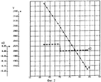
на фиг.2 показаны изменения по времени относительной скорости V и перегрузки nD по оси ХD, в направлении которой равна нулю перегрузка от проекция вектора полной аэродинамической силы.figure 2 shows the changes in time of the relative speed V and the overload n D along the X D axis, in the direction of which the overload from the projection of the total aerodynamic force vector is zero.
Предлагаемый способ осуществляют в следующей последовательности.The proposed method is carried out in the following sequence.
Способ определения вектора силы тяги гиперзвукового прямоточного воздушно-реактивного двигателя (ГПВРД)2 с косым срезом сопла по результатам летных испытаний его на гиперзвуковой летающей лаборатории (ГЛЛ)1 включает измерение перегрузки на ГЛЛ от действия силы тяги двигателя (схема ориентации измерительной оси акселерометра и действующих на ГЛЛ сил показана на фиг.1) осуществляют в следующей последовательностиA method for determining the thrust vector of a hypersonic ramjet engine (SCRE) 2 with oblique cut of the nozzle according to the results of its flight tests at a hypersonic flying laboratory (HLL) 1 includes measuring the overload on the HLL from the action of the engine’s thrust force (orientation of the measuring axis of the accelerometer and operating on GLL forces shown in figure 1) is carried out in the following sequence
- измерительную ось акселерометра поворачивают относительно связанной продольной оси оХ1 ГЛЛ;- the measuring axis of the accelerometer is rotated relative to the associated longitudinal axis oX 1 GLL;
- угол наклона измерительной оси выбирают из условия равенства нулю проекции вектора полной аэродинамической силы, используя заданные аэродинамические характеристики ГЛЛ с большим аэродинамическим качеством, определяют значение угла по формуле:- the angle of inclination of the measuring axis is selected from the condition that the projection of the total aerodynamic force vector is zero, using the specified aerodynamic characteristics of the HLL with high aerodynamic quality, determine the angle by the formula:
![]()
![]()
αD - угол наклони измерительной оси акселерометра относительно оси оХ1 ГЛЛ,α D is the angle of inclination of the measuring axis of the accelerometer relative to the axis oX 1 GLL,
К - аэродинамическое качество.K - aerodynamic quality.
α - угол атаки;α is the angle of attack;
- измеряют перегрузку на ГЛЛ от действия силы тяги двигателя;- measure the overload on the HLL from the action of the engine traction force;
- по результатам внешнетраекторных измерений вычисляют ускорение в направлении вектора относительной скорости, для этого из результатов измерений относительной скорости выбирают значения ее в начале и в конце малого интервала времени Δt=1...5 с на участке свободного полета перед включением двигателя и после его выключения по окончанию работы, на участке работы двигателя после его включения и перед выключением, определяют ускорение, используя формулы численного дифференцирования:- according to the results of external trajectory measurements, the acceleration in the direction of the relative velocity vector is calculated; for this, from the relative velocity measurement results, select its values at the beginning and at the end of a small time interval Δ t = 1 ... 5 s in the free flight section before and after the engine is turned on shutdown at the end of work, on the site of the engine after it is turned on and before shutting down, determine the acceleration using the numerical differentiation formulas:
![]()
![]()
![]()
![]()
где Δt - малый интервал времени (1...5 с),where Δt is a small time interval (1 ... 5 s),
νi, νJ, νi+1, νJ+1 - измеренные значения относительной скорости в начале и в конце указанных интервалов времени Δti,ΔtJ.ν i , ν J , ν i + 1 , ν J + 1 - measured values of the relative speed at the beginning and at the end of the indicated time intervals Δt i , Δt J.
сравнивают эти ускорения и вычисляют результирующее ускорение, характеризуемое работой двигателя, но формуле: ![]()
![]()
- определяют угол поворота φ вектора силы тяги для двигателя с косым срезом сопла по формуле:- determine the angle of rotation φ of the thrust force vector for an engine with an oblique cut of the nozzle according to the formula:
![]()
![]()
где nD - измеренное в полете значение перегрузки под углом αD,where n D is the measured in flight value of the overload at an angle α D ,
g - ускорение силы тяжести,g is the acceleration of gravity,
- с учетом угла поворота вектора силы тяги вычисляют модуль его по формулам:- taking into account the angle of rotation of the thrust force vector, its module is calculated by the formulas:
![]()
![]()
![]()
![]()
первую или вторую формулу используют и зависимости от точности проведенных в летном эксперименте измерений.the first or second formula is also used depending on the accuracy of measurements made in a flight experiment.
Пример 1.Example 1
Для проверки предложенного способа определения вектора силы тяги двигателя проведена обработка показаний акселерометра и результатов внешнетраекторных измерений относительной скорости, полученных при математическом моделировании пространственного движения ГЛЛ. Используются результаты моделирования траектории на экспериментальном участке (интервал времени 40...70 с). Приняты исходные данные: Р=100 кгс, φ=-20°, G=1451 кг; заданы аэродинамические характеристики ГЛЛ в зависимости от числа М и угла атаки. Представлены результат вычислений угла поворота оси чувствительности акселерометра, результаты математического моделирования пространственного движения ГЛЛ и результаты вычисления дополнительного ускорения в направлении вектора относительной скорости при включении двигателя.To verify the proposed method for determining the thrust vector of the engine, the accelerometer readings and the results of external trajectory measurements of the relative velocity obtained by mathematical modeling of the spatial motion of the HLL were processed. The results of modeling the trajectory in the experimental section (time interval 40 ... 70 s) are used. The initial data are accepted: P = 100 kgf, φ = -20 °, G = 1451 kg; GDL aerodynamic characteristics are set depending on the number M and the angle of attack. The results of calculating the angle of rotation of the sensitivity axis of the accelerometer, the results of mathematical modeling of the spatial motion of the HLL and the results of calculating the additional acceleration in the direction of the relative velocity vector when the engine is turned on are presented.
Для рассматриваемой компоновки ГЛЛ получено αD=-24.5°, ось чувствительности - вверх относительно строительной оси ГЛЛ.For the considered GLL arrangement, α D = -24.5 ° was obtained, the sensitivity axis is upward relative to the GLL construction axis.
Результаты математическою моделирования конечного участка траектории в окрестности момента выключения двигателя (t=70 с) представлены на фиг.2 и в таблице 1; для удобства вычислений принят интервал Δt=1 с.The results of mathematical modeling of the final portion of the trajectory in the vicinity of the moment the engine is turned off (t = 70 s) are presented in figure 2 and in table 1; for convenience of calculations, the interval Δt = 1 s is adopted.
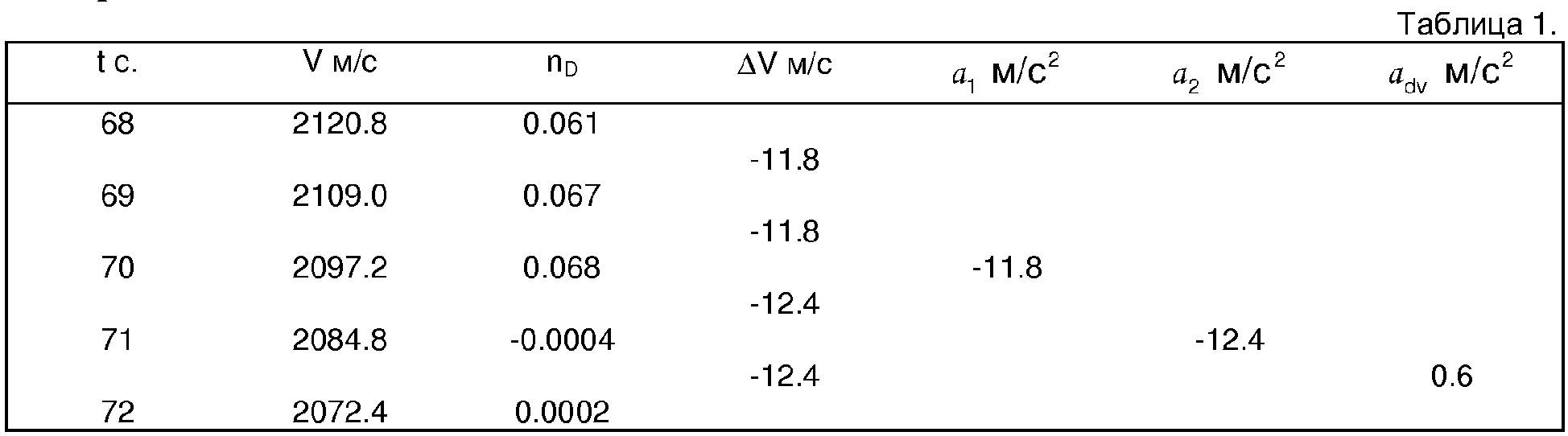
По показаниям акселерометра nD в процессе послеполетной обработки вычисляется ускорение вдоль оси чувствительности акселерометра, а по результатам внешне траекторных измерений - ускорение в направлении вектора скорости. По формуле (5) вычисляется угол поворота вектора силы тяги, а по формулам (6) и (7) - модуль вектора силы тяги. Для представленных результатов моделирования получено φ=-20,5°, Р=99.7 кгс, что практически совпадает с исходными значениями (φ=-20°, Р=100 кгс).According to the readings of the accelerometer n D in the process of post-flight processing, the acceleration along the sensitivity axis of the accelerometer is calculated, and according to the results of externally trajectory measurements, the acceleration in the direction of the velocity vector. By the formula (5), the rotation angle of the traction force vector is calculated, and by the formulas (6) and (7), the module of the traction force vector is calculated. For the presented simulation results, φ = -20.5 °, P = 99.7 kgf, which is almost the same as the initial values (φ = -20 °, P = 100 kgf).
Предложенный способ может быть использован для определения модуля и угла поворота вектора силы тяги по результатам измерений перегрузки и результатам внешнетраекторных измерений при осуществлении полетов летательных аппаратов с прямоточными и ракетными двигателями.The proposed method can be used to determine the module and the angle of rotation of the thrust force vector from the results of measurements of overload and the results of external trajectory measurements when flying aircraft with ramjets and rocket engines.
Claims (1)
Priority Applications (1)
| Application Number | Priority Date | Filing Date | Title |
|---|---|---|---|
| RU2006125560/28A RU2314503C1 (en) | 2006-07-18 | 2006-07-18 | Method of determining thrust vector of ram-jet engine |
Applications Claiming Priority (1)
| Application Number | Priority Date | Filing Date | Title |
|---|---|---|---|
| RU2006125560/28A RU2314503C1 (en) | 2006-07-18 | 2006-07-18 | Method of determining thrust vector of ram-jet engine |
Publications (1)
| Publication Number | Publication Date |
|---|---|
| RU2314503C1 true RU2314503C1 (en) | 2008-01-10 |
Family
ID=39020240
Family Applications (1)
| Application Number | Title | Priority Date | Filing Date |
|---|---|---|---|
| RU2006125560/28A RU2314503C1 (en) | 2006-07-18 | 2006-07-18 | Method of determining thrust vector of ram-jet engine |
Country Status (1)
| Country | Link |
|---|---|
| RU (1) | RU2314503C1 (en) |
Cited By (4)
| Publication number | Priority date | Publication date | Assignee | Title |
|---|---|---|---|---|
| RU2364846C1 (en) * | 2008-03-14 | 2009-08-20 | Федеральное государственное унитарное предприятие "Летно-исследовательский институт имени М.М. Громова" | Method for automated assessment of aircraft engines total thrust in process of flight |
| RU2445599C1 (en) * | 2010-12-03 | 2012-03-20 | Федеральное государственное унитарное предприятие "Летно-исследовательский институт имени М.М. Громова" | Method for determining turning angle of thrust vector of hypersonic once-through air jet engine with chamfer cut of nozzle as per results of flight tests on hypersonic flying laboratory |
| RU2503941C1 (en) * | 2012-07-09 | 2014-01-10 | Открытое акционерное общество "Лётно-исследовательский институт имени М.М. Громова" | Method to determine aerodynamic coefficients cx and cy based on detection of total traction of propulsion device according to results of flight tests of aircraft |
| RU2610329C1 (en) * | 2015-10-23 | 2017-02-09 | Федеральное государственное унитарное предприятие "Центральный институт авиационного моторостроения им. П.И. Баранова" | Method to test high speed aircraft |
Citations (4)
| Publication number | Priority date | Publication date | Assignee | Title |
|---|---|---|---|---|
| EP0342970A2 (en) * | 1988-05-19 | 1989-11-23 | Control Data Canada Limited | Method & apparatus for real-time measurement of the net thrust of a jet engine |
| RU2059252C1 (en) * | 1993-07-09 | 1996-04-27 | Казанский государственный технический университет им.А.Н.Туполева | Method of detecting vertical speed of object and apparatus for performing the method |
| RU2242736C2 (en) * | 2003-02-26 | 2004-12-20 | Федеральное государственное унитарное предприятие "Центральный институт авиационного моторостроения им. П.И. Баранова" | Method of measuring flight thrust of hypersonic ramjet engine of unmanned hypersonic flying laboratory |
| RU2274764C2 (en) * | 2003-12-16 | 2006-04-20 | Федеральное государственное унитарное предприятие "Московский институт теплотехники" | Stand for testing engines with skewed nozzle |
-
2006
- 2006-07-18 RU RU2006125560/28A patent/RU2314503C1/en not_active IP Right Cessation
Patent Citations (4)
| Publication number | Priority date | Publication date | Assignee | Title |
|---|---|---|---|---|
| EP0342970A2 (en) * | 1988-05-19 | 1989-11-23 | Control Data Canada Limited | Method & apparatus for real-time measurement of the net thrust of a jet engine |
| RU2059252C1 (en) * | 1993-07-09 | 1996-04-27 | Казанский государственный технический университет им.А.Н.Туполева | Method of detecting vertical speed of object and apparatus for performing the method |
| RU2242736C2 (en) * | 2003-02-26 | 2004-12-20 | Федеральное государственное унитарное предприятие "Центральный институт авиационного моторостроения им. П.И. Баранова" | Method of measuring flight thrust of hypersonic ramjet engine of unmanned hypersonic flying laboratory |
| RU2274764C2 (en) * | 2003-12-16 | 2006-04-20 | Федеральное государственное унитарное предприятие "Московский институт теплотехники" | Stand for testing engines with skewed nozzle |
Non-Patent Citations (1)
| Title |
|---|
| Браилко И.А., Клестов Ю.М., Крашенинников С.Ю., Миронов А.К. Экспериментальное и расчетное исследование аэродинамики плоского поворотного сопла с резким изменением контура в горле/ ЦИАМ им. П.И.Баранова. - Аэромеханика и газовая динамика, №3. * |
Cited By (4)
| Publication number | Priority date | Publication date | Assignee | Title |
|---|---|---|---|---|
| RU2364846C1 (en) * | 2008-03-14 | 2009-08-20 | Федеральное государственное унитарное предприятие "Летно-исследовательский институт имени М.М. Громова" | Method for automated assessment of aircraft engines total thrust in process of flight |
| RU2445599C1 (en) * | 2010-12-03 | 2012-03-20 | Федеральное государственное унитарное предприятие "Летно-исследовательский институт имени М.М. Громова" | Method for determining turning angle of thrust vector of hypersonic once-through air jet engine with chamfer cut of nozzle as per results of flight tests on hypersonic flying laboratory |
| RU2503941C1 (en) * | 2012-07-09 | 2014-01-10 | Открытое акционерное общество "Лётно-исследовательский институт имени М.М. Громова" | Method to determine aerodynamic coefficients cx and cy based on detection of total traction of propulsion device according to results of flight tests of aircraft |
| RU2610329C1 (en) * | 2015-10-23 | 2017-02-09 | Федеральное государственное унитарное предприятие "Центральный институт авиационного моторостроения им. П.И. Баранова" | Method to test high speed aircraft |
Similar Documents
| Publication | Publication Date | Title |
|---|---|---|
| US6273370B1 (en) | Method and system for estimation and correction of angle-of-attack and sideslip angle from acceleration measurements | |
| US6253166B1 (en) | Stable algorithm for estimating airdata from flush surface pressure measurements | |
| US6807468B2 (en) | Method for estimating wind | |
| RU2445599C1 (en) | Method for determining turning angle of thrust vector of hypersonic once-through air jet engine with chamfer cut of nozzle as per results of flight tests on hypersonic flying laboratory | |
| Wang et al. | Retrospective and recent examples of aircraft parameter identification at NASA Dryden Flight Research Center | |
| Bollay | Aerodynamic stability and automatic control: The fourteenth wright brothers lecture | |
| CN111350616B (en) | A method for measuring tiny thrust eccentricity of solid engines under unconstrained conditions | |
| RU2314503C1 (en) | Method of determining thrust vector of ram-jet engine | |
| CN106125571B (en) | A Modeling Method for Speed Control of Cruise Missile | |
| RU2364846C1 (en) | Method for automated assessment of aircraft engines total thrust in process of flight | |
| RU2347193C1 (en) | Methods of determination of attack angles and slide at flight trials of supersonic flying machine | |
| RU2324156C2 (en) | Method of determining tractive force of hipersonic direct flow aerojet engine from results of flying experiments in hypersonic flying laboratories | |
| RU2242736C2 (en) | Method of measuring flight thrust of hypersonic ramjet engine of unmanned hypersonic flying laboratory | |
| Oliveira et al. | Output error method and two step method for aerodynamic model identification | |
| Lyu et al. | A novel integrated navigation system based on the quadrotor dynamic model | |
| RU2579796C1 (en) | Method of determining aircraft engine thrust | |
| Siu et al. | Flight test results of an angle of attack and angle of sideslip calibration method using Output-Error optimization | |
| Raab | Rapid aerodynamic parameter identification on a large transport aircraft | |
| RU2790358C1 (en) | Method for determining aircraft aerodynamic characteristics based on flight experiment results | |
| Gray | An investigation of open-loop and inverse simulation as nonlinear model validation tools for helicopter flight mechanics | |
| Shaw et al. | An experimental investigation of a highly underexpanded sonic jet ejecting from a flat plate into a subsonic crossflow | |
| Franze | SHEFEX II-a first aerodynamic and atmospheric post-flight analysis | |
| Nusrath et al. | Drag assessment of a high performance aircraft using system identification techniques | |
| Lauten et al. | Continuation of wing flutter investigation in the transonic range and presentation of a limited summary of flutter data | |
| RU2503941C1 (en) | Method to determine aerodynamic coefficients cx and cy based on detection of total traction of propulsion device according to results of flight tests of aircraft |
Legal Events
| Date | Code | Title | Description |
|---|---|---|---|
| PC43 | Official registration of the transfer of the exclusive right without contract for inventions |
Effective date: 20120827 |
|
| MM4A | The patent is invalid due to non-payment of fees |
Effective date: 20150719 |