RU2310704C2 - Surface covering with selectively formed embossment and method for manufacturing the same - Google Patents
Surface covering with selectively formed embossment and method for manufacturing the same Download PDFInfo
- Publication number
- RU2310704C2 RU2310704C2 RU2006102871/04A RU2006102871A RU2310704C2 RU 2310704 C2 RU2310704 C2 RU 2310704C2 RU 2006102871/04 A RU2006102871/04 A RU 2006102871/04A RU 2006102871 A RU2006102871 A RU 2006102871A RU 2310704 C2 RU2310704 C2 RU 2310704C2
- Authority
- RU
- Russia
- Prior art keywords
- coating
- photoinitiator
- layer
- plastic
- stage
- Prior art date
Links
- 238000000034 method Methods 0.000 title claims abstract description 53
- 238000004519 manufacturing process Methods 0.000 title claims description 4
- 238000000576 coating method Methods 0.000 claims abstract description 164
- 239000011248 coating agent Substances 0.000 claims abstract description 139
- 229920003023 plastic Polymers 0.000 claims abstract description 76
- 239000004033 plastic Substances 0.000 claims abstract description 76
- 230000003213 activating effect Effects 0.000 claims abstract description 8
- 238000010438 heat treatment Methods 0.000 claims abstract description 8
- 238000007639 printing Methods 0.000 claims description 80
- 239000003112 inhibitor Substances 0.000 claims description 29
- 238000004049 embossing Methods 0.000 claims description 28
- 230000005855 radiation Effects 0.000 claims description 21
- 239000003973 paint Substances 0.000 claims description 16
- 230000004913 activation Effects 0.000 claims description 15
- 239000004088 foaming agent Substances 0.000 claims description 13
- 239000003999 initiator Substances 0.000 claims description 12
- 239000007788 liquid Substances 0.000 claims description 12
- 229920001944 Plastisol Polymers 0.000 claims description 10
- 239000004999 plastisol Substances 0.000 claims description 10
- 229920000642 polymer Polymers 0.000 claims description 10
- 239000004604 Blowing Agent Substances 0.000 claims description 9
- 230000005670 electromagnetic radiation Effects 0.000 claims description 8
- 238000001879 gelation Methods 0.000 claims description 8
- 239000006260 foam Substances 0.000 claims description 7
- 229920002635 polyurethane Polymers 0.000 claims description 6
- 239000004814 polyurethane Substances 0.000 claims description 6
- 238000013508 migration Methods 0.000 claims description 4
- 230000005012 migration Effects 0.000 claims description 4
- 238000001035 drying Methods 0.000 claims description 2
- 238000010894 electron beam technology Methods 0.000 claims description 2
- 150000003673 urethanes Chemical class 0.000 claims description 2
- 238000009792 diffusion process Methods 0.000 claims 1
- 239000011527 polyurethane coating Substances 0.000 claims 1
- 230000000694 effects Effects 0.000 abstract description 10
- 239000000758 substrate Substances 0.000 abstract description 10
- 239000000126 substance Substances 0.000 abstract description 4
- 230000015572 biosynthetic process Effects 0.000 abstract description 2
- 239000000976 ink Substances 0.000 description 76
- 239000000047 product Substances 0.000 description 47
- 238000001723 curing Methods 0.000 description 26
- 239000000463 material Substances 0.000 description 18
- 239000000203 mixture Substances 0.000 description 14
- 239000004575 stone Substances 0.000 description 9
- 239000002023 wood Substances 0.000 description 9
- 239000011083 cement mortar Substances 0.000 description 8
- 239000000919 ceramic Substances 0.000 description 8
- 238000004132 cross linking Methods 0.000 description 8
- 239000004800 polyvinyl chloride Substances 0.000 description 7
- -1 sandstone Substances 0.000 description 7
- 229920000915 polyvinyl chloride Polymers 0.000 description 6
- 238000003490 calendering Methods 0.000 description 5
- 239000004568 cement Substances 0.000 description 5
- 239000007799 cork Substances 0.000 description 5
- 239000004014 plasticizer Substances 0.000 description 5
- 239000002002 slurry Substances 0.000 description 5
- 239000011449 brick Substances 0.000 description 4
- 238000001816 cooling Methods 0.000 description 4
- 238000005469 granulation Methods 0.000 description 4
- 230000003179 granulation Effects 0.000 description 4
- 239000011431 lime mortar Substances 0.000 description 4
- 239000003381 stabilizer Substances 0.000 description 4
- XLYOFNOQVPJJNP-UHFFFAOYSA-N water Substances O XLYOFNOQVPJJNP-UHFFFAOYSA-N 0.000 description 4
- 125000004432 carbon atom Chemical group C* 0.000 description 3
- 239000003086 colorant Substances 0.000 description 3
- 238000013461 design Methods 0.000 description 3
- 238000001125 extrusion Methods 0.000 description 3
- 239000000945 filler Substances 0.000 description 3
- 229920005989 resin Polymers 0.000 description 3
- 239000011347 resin Substances 0.000 description 3
- 230000003595 spectral effect Effects 0.000 description 3
- 238000001228 spectrum Methods 0.000 description 3
- CSCPPACGZOOCGX-UHFFFAOYSA-N Acetone Chemical compound CC(C)=O CSCPPACGZOOCGX-UHFFFAOYSA-N 0.000 description 2
- 239000004156 Azodicarbonamide Substances 0.000 description 2
- VYZAMTAEIAYCRO-UHFFFAOYSA-N Chromium Chemical compound [Cr] VYZAMTAEIAYCRO-UHFFFAOYSA-N 0.000 description 2
- RTZKZFJDLAIYFH-UHFFFAOYSA-N Diethyl ether Chemical compound CCOCC RTZKZFJDLAIYFH-UHFFFAOYSA-N 0.000 description 2
- VZCYOOQTPOCHFL-OWOJBTEDSA-N Fumaric acid Chemical compound OC(=O)\C=C\C(O)=O VZCYOOQTPOCHFL-OWOJBTEDSA-N 0.000 description 2
- UQSXHKLRYXJYBZ-UHFFFAOYSA-N Iron oxide Chemical compound [Fe]=O UQSXHKLRYXJYBZ-UHFFFAOYSA-N 0.000 description 2
- 239000004793 Polystyrene Substances 0.000 description 2
- GWEVSGVZZGPLCZ-UHFFFAOYSA-N Titan oxide Chemical compound O=[Ti]=O GWEVSGVZZGPLCZ-UHFFFAOYSA-N 0.000 description 2
- 238000003848 UV Light-Curing Methods 0.000 description 2
- XOZUGNYVDXMRKW-AATRIKPKSA-N azodicarbonamide Chemical compound NC(=O)\N=N\C(N)=O XOZUGNYVDXMRKW-AATRIKPKSA-N 0.000 description 2
- 235000019399 azodicarbonamide Nutrition 0.000 description 2
- ISAOCJYIOMOJEB-UHFFFAOYSA-N benzoin Chemical compound C=1C=CC=CC=1C(O)C(=O)C1=CC=CC=C1 ISAOCJYIOMOJEB-UHFFFAOYSA-N 0.000 description 2
- 239000003054 catalyst Substances 0.000 description 2
- 239000000835 fiber Substances 0.000 description 2
- 230000004907 flux Effects 0.000 description 2
- 238000005187 foaming Methods 0.000 description 2
- 230000004927 fusion Effects 0.000 description 2
- 238000009499 grossing Methods 0.000 description 2
- 230000000977 initiatory effect Effects 0.000 description 2
- 238000002844 melting Methods 0.000 description 2
- 230000008018 melting Effects 0.000 description 2
- 239000002245 particle Substances 0.000 description 2
- 239000003505 polymerization initiator Substances 0.000 description 2
- 229920000098 polyolefin Polymers 0.000 description 2
- 229920002223 polystyrene Polymers 0.000 description 2
- 238000012545 processing Methods 0.000 description 2
- 238000005096 rolling process Methods 0.000 description 2
- 239000004576 sand Substances 0.000 description 2
- 238000007650 screen-printing Methods 0.000 description 2
- 239000002904 solvent Substances 0.000 description 2
- 238000005507 spraying Methods 0.000 description 2
- 229920003002 synthetic resin Polymers 0.000 description 2
- 239000000057 synthetic resin Substances 0.000 description 2
- 238000001029 thermal curing Methods 0.000 description 2
- MSAHTMIQULFMRG-UHFFFAOYSA-N 1,2-diphenyl-2-propan-2-yloxyethanone Chemical compound C=1C=CC=CC=1C(OC(C)C)C(=O)C1=CC=CC=C1 MSAHTMIQULFMRG-UHFFFAOYSA-N 0.000 description 1
- PIZHFBODNLEQBL-UHFFFAOYSA-N 2,2-diethoxy-1-phenylethanone Chemical compound CCOC(OCC)C(=O)C1=CC=CC=C1 PIZHFBODNLEQBL-UHFFFAOYSA-N 0.000 description 1
- KMNCBSZOIQAUFX-UHFFFAOYSA-N 2-ethoxy-1,2-diphenylethanone Chemical compound C=1C=CC=CC=1C(OCC)C(=O)C1=CC=CC=C1 KMNCBSZOIQAUFX-UHFFFAOYSA-N 0.000 description 1
- LRRQSCPPOIUNGX-UHFFFAOYSA-N 2-hydroxy-1,2-bis(4-methoxyphenyl)ethanone Chemical compound C1=CC(OC)=CC=C1C(O)C(=O)C1=CC=C(OC)C=C1 LRRQSCPPOIUNGX-UHFFFAOYSA-N 0.000 description 1
- KTALPKYXQZGAEG-UHFFFAOYSA-N 2-propan-2-ylthioxanthen-9-one Chemical compound C1=CC=C2C(=O)C3=CC(C(C)C)=CC=C3SC2=C1 KTALPKYXQZGAEG-UHFFFAOYSA-N 0.000 description 1
- NBOCQTNZUPTTEI-UHFFFAOYSA-N 4-[4-(hydrazinesulfonyl)phenoxy]benzenesulfonohydrazide Chemical compound C1=CC(S(=O)(=O)NN)=CC=C1OC1=CC=C(S(=O)(=O)NN)C=C1 NBOCQTNZUPTTEI-UHFFFAOYSA-N 0.000 description 1
- CMGDVUCDZOBDNL-UHFFFAOYSA-N 4-methyl-2h-benzotriazole Chemical compound CC1=CC=CC2=NNN=C12 CMGDVUCDZOBDNL-UHFFFAOYSA-N 0.000 description 1
- BMVWCPGVLSILMU-UHFFFAOYSA-N 5,6-dihydrodibenzo[2,1-b:2',1'-f][7]annulen-11-one Chemical compound C1CC2=CC=CC=C2C(=O)C2=CC=CC=C21 BMVWCPGVLSILMU-UHFFFAOYSA-N 0.000 description 1
- 206010000060 Abdominal distension Diseases 0.000 description 1
- NIXOWILDQLNWCW-UHFFFAOYSA-M Acrylate Chemical compound [O-]C(=O)C=C NIXOWILDQLNWCW-UHFFFAOYSA-M 0.000 description 1
- 102100035474 DNA polymerase kappa Human genes 0.000 description 1
- 101710108091 DNA polymerase kappa Proteins 0.000 description 1
- 206010073306 Exposure to radiation Diseases 0.000 description 1
- 239000006057 Non-nutritive feed additive Substances 0.000 description 1
- 229920012485 Plasticized Polyvinyl chloride Polymers 0.000 description 1
- 239000004952 Polyamide Substances 0.000 description 1
- 239000004698 Polyethylene Substances 0.000 description 1
- 239000004743 Polypropylene Substances 0.000 description 1
- 235000000126 Styrax benzoin Nutrition 0.000 description 1
- 244000028419 Styrax benzoin Species 0.000 description 1
- 235000008411 Sumatra benzointree Nutrition 0.000 description 1
- BZHJMEDXRYGGRV-UHFFFAOYSA-N Vinyl chloride Chemical compound ClC=C BZHJMEDXRYGGRV-UHFFFAOYSA-N 0.000 description 1
- 150000001252 acrylic acid derivatives Chemical class 0.000 description 1
- 239000000654 additive Substances 0.000 description 1
- 125000000217 alkyl group Chemical group 0.000 description 1
- 125000003118 aryl group Chemical group 0.000 description 1
- 229960002130 benzoin Drugs 0.000 description 1
- RWCCWEUUXYIKHB-UHFFFAOYSA-N benzophenone Chemical compound C=1C=CC=CC=1C(=O)C1=CC=CC=C1 RWCCWEUUXYIKHB-UHFFFAOYSA-N 0.000 description 1
- 239000012965 benzophenone Substances 0.000 description 1
- QRUDEWIWKLJBPS-UHFFFAOYSA-N benzotriazole Chemical compound C1=CC=C2N[N][N]C2=C1 QRUDEWIWKLJBPS-UHFFFAOYSA-N 0.000 description 1
- 239000012964 benzotriazole Substances 0.000 description 1
- 208000024330 bloating Diseases 0.000 description 1
- 239000006229 carbon black Substances 0.000 description 1
- 239000001913 cellulose Substances 0.000 description 1
- 229920002678 cellulose Polymers 0.000 description 1
- 238000005253 cladding Methods 0.000 description 1
- 239000008199 coating composition Substances 0.000 description 1
- 238000000354 decomposition reaction Methods 0.000 description 1
- 230000008021 deposition Effects 0.000 description 1
- 238000010586 diagram Methods 0.000 description 1
- 239000006185 dispersion Substances 0.000 description 1
- 229920006242 ethylene acrylic acid copolymer Polymers 0.000 description 1
- 238000001704 evaporation Methods 0.000 description 1
- 230000008020 evaporation Effects 0.000 description 1
- 239000004744 fabric Substances 0.000 description 1
- 239000012467 final product Substances 0.000 description 1
- 238000009472 formulation Methods 0.000 description 1
- 239000001530 fumaric acid Substances 0.000 description 1
- 239000011521 glass Substances 0.000 description 1
- 235000019382 gum benzoic Nutrition 0.000 description 1
- 229920001519 homopolymer Polymers 0.000 description 1
- 238000005470 impregnation Methods 0.000 description 1
- 239000004615 ingredient Substances 0.000 description 1
- 230000005764 inhibitory process Effects 0.000 description 1
- 239000001023 inorganic pigment Substances 0.000 description 1
- 238000009434 installation Methods 0.000 description 1
- 229920000554 ionomer Polymers 0.000 description 1
- 238000003475 lamination Methods 0.000 description 1
- 239000006193 liquid solution Substances 0.000 description 1
- 238000012423 maintenance Methods 0.000 description 1
- 150000002734 metacrylic acid derivatives Chemical class 0.000 description 1
- 229910052751 metal Inorganic materials 0.000 description 1
- 239000002184 metal Substances 0.000 description 1
- 229920003145 methacrylic acid copolymer Polymers 0.000 description 1
- 239000010445 mica Substances 0.000 description 1
- 229910052618 mica group Inorganic materials 0.000 description 1
- 239000002557 mineral fiber Substances 0.000 description 1
- 239000000178 monomer Substances 0.000 description 1
- 239000000025 natural resin Substances 0.000 description 1
- 239000011146 organic particle Substances 0.000 description 1
- 239000012860 organic pigment Substances 0.000 description 1
- 239000003960 organic solvent Substances 0.000 description 1
- 238000010422 painting Methods 0.000 description 1
- 239000013618 particulate matter Substances 0.000 description 1
- 238000005192 partition Methods 0.000 description 1
- 150000002978 peroxides Chemical class 0.000 description 1
- 230000019612 pigmentation Effects 0.000 description 1
- 229920002647 polyamide Polymers 0.000 description 1
- 229920000728 polyester Polymers 0.000 description 1
- 229920000573 polyethylene Polymers 0.000 description 1
- 238000006116 polymerization reaction Methods 0.000 description 1
- 229920001155 polypropylene Polymers 0.000 description 1
- 238000003825 pressing Methods 0.000 description 1
- 238000007761 roller coating Methods 0.000 description 1
- 230000035945 sensitivity Effects 0.000 description 1
- 239000010454 slate Substances 0.000 description 1
- 239000007787 solid Substances 0.000 description 1
- 125000001424 substituent group Chemical group 0.000 description 1
- 230000008961 swelling Effects 0.000 description 1
- 239000004753 textile Substances 0.000 description 1
- 229920001169 thermoplastic Polymers 0.000 description 1
- 229920002725 thermoplastic elastomer Polymers 0.000 description 1
- 229920001187 thermosetting polymer Polymers 0.000 description 1
- 239000004416 thermosoftening plastic Substances 0.000 description 1
- 239000004408 titanium dioxide Substances 0.000 description 1
- VZCYOOQTPOCHFL-UHFFFAOYSA-N trans-butenedioic acid Natural products OC(=O)C=CC(O)=O VZCYOOQTPOCHFL-UHFFFAOYSA-N 0.000 description 1
- 230000001960 triggered effect Effects 0.000 description 1
- SRPWOOOHEPICQU-UHFFFAOYSA-N trimellitic anhydride Chemical compound OC(=O)C1=CC=C2C(=O)OC(=O)C2=C1 SRPWOOOHEPICQU-UHFFFAOYSA-N 0.000 description 1
- 238000009281 ultraviolet germicidal irradiation Methods 0.000 description 1
- 230000003313 weakening effect Effects 0.000 description 1
- 238000004804 winding Methods 0.000 description 1
Images


Classifications
-
- B—PERFORMING OPERATIONS; TRANSPORTING
- B32—LAYERED PRODUCTS
- B32B—LAYERED PRODUCTS, i.e. PRODUCTS BUILT-UP OF STRATA OF FLAT OR NON-FLAT, e.g. CELLULAR OR HONEYCOMB, FORM
- B32B5/00—Layered products characterised by the non- homogeneity or physical structure, i.e. comprising a fibrous, filamentary, particulate or foam layer; Layered products characterised by having a layer differing constitutionally or physically in different parts
- B32B5/18—Layered products characterised by the non- homogeneity or physical structure, i.e. comprising a fibrous, filamentary, particulate or foam layer; Layered products characterised by having a layer differing constitutionally or physically in different parts characterised by features of a layer of foamed material
-
- B—PERFORMING OPERATIONS; TRANSPORTING
- B29—WORKING OF PLASTICS; WORKING OF SUBSTANCES IN A PLASTIC STATE IN GENERAL
- B29C—SHAPING OR JOINING OF PLASTICS; SHAPING OF MATERIAL IN A PLASTIC STATE, NOT OTHERWISE PROVIDED FOR; AFTER-TREATMENT OF THE SHAPED PRODUCTS, e.g. REPAIRING
- B29C59/00—Surface shaping of articles, e.g. embossing; Apparatus therefor
- B29C59/02—Surface shaping of articles, e.g. embossing; Apparatus therefor by mechanical means, e.g. pressing
- B29C59/04—Surface shaping of articles, e.g. embossing; Apparatus therefor by mechanical means, e.g. pressing using rollers or endless belts
- B29C59/046—Surface shaping of articles, e.g. embossing; Apparatus therefor by mechanical means, e.g. pressing using rollers or endless belts for layered or coated substantially flat surfaces
-
- B—PERFORMING OPERATIONS; TRANSPORTING
- B29—WORKING OF PLASTICS; WORKING OF SUBSTANCES IN A PLASTIC STATE IN GENERAL
- B29C—SHAPING OR JOINING OF PLASTICS; SHAPING OF MATERIAL IN A PLASTIC STATE, NOT OTHERWISE PROVIDED FOR; AFTER-TREATMENT OF THE SHAPED PRODUCTS, e.g. REPAIRING
- B29C59/00—Surface shaping of articles, e.g. embossing; Apparatus therefor
- B29C59/16—Surface shaping of articles, e.g. embossing; Apparatus therefor by wave energy or particle radiation, e.g. infrared heating
-
- B—PERFORMING OPERATIONS; TRANSPORTING
- B32—LAYERED PRODUCTS
- B32B—LAYERED PRODUCTS, i.e. PRODUCTS BUILT-UP OF STRATA OF FLAT OR NON-FLAT, e.g. CELLULAR OR HONEYCOMB, FORM
- B32B27/00—Layered products comprising a layer of synthetic resin
- B32B27/12—Layered products comprising a layer of synthetic resin next to a fibrous or filamentary layer
-
- B—PERFORMING OPERATIONS; TRANSPORTING
- B32—LAYERED PRODUCTS
- B32B—LAYERED PRODUCTS, i.e. PRODUCTS BUILT-UP OF STRATA OF FLAT OR NON-FLAT, e.g. CELLULAR OR HONEYCOMB, FORM
- B32B3/00—Layered products comprising a layer with external or internal discontinuities or unevennesses, or a layer of non-planar form; Layered products having particular features of form
- B32B3/26—Layered products comprising a layer with external or internal discontinuities or unevennesses, or a layer of non-planar form; Layered products having particular features of form characterised by a particular shape of the outline of the cross-section of a continuous layer; characterised by a layer with cavities or internal voids ; characterised by an apertured layer
- B32B3/30—Layered products comprising a layer with external or internal discontinuities or unevennesses, or a layer of non-planar form; Layered products having particular features of form characterised by a particular shape of the outline of the cross-section of a continuous layer; characterised by a layer with cavities or internal voids ; characterised by an apertured layer characterised by a layer formed with recesses or projections, e.g. hollows, grooves, protuberances, ribs
-
- B—PERFORMING OPERATIONS; TRANSPORTING
- B32—LAYERED PRODUCTS
- B32B—LAYERED PRODUCTS, i.e. PRODUCTS BUILT-UP OF STRATA OF FLAT OR NON-FLAT, e.g. CELLULAR OR HONEYCOMB, FORM
- B32B38/00—Ancillary operations in connection with laminating processes
-
- B—PERFORMING OPERATIONS; TRANSPORTING
- B32—LAYERED PRODUCTS
- B32B—LAYERED PRODUCTS, i.e. PRODUCTS BUILT-UP OF STRATA OF FLAT OR NON-FLAT, e.g. CELLULAR OR HONEYCOMB, FORM
- B32B38/00—Ancillary operations in connection with laminating processes
- B32B38/06—Embossing
-
- B—PERFORMING OPERATIONS; TRANSPORTING
- B32—LAYERED PRODUCTS
- B32B—LAYERED PRODUCTS, i.e. PRODUCTS BUILT-UP OF STRATA OF FLAT OR NON-FLAT, e.g. CELLULAR OR HONEYCOMB, FORM
- B32B5/00—Layered products characterised by the non- homogeneity or physical structure, i.e. comprising a fibrous, filamentary, particulate or foam layer; Layered products characterised by having a layer differing constitutionally or physically in different parts
- B32B5/18—Layered products characterised by the non- homogeneity or physical structure, i.e. comprising a fibrous, filamentary, particulate or foam layer; Layered products characterised by having a layer differing constitutionally or physically in different parts characterised by features of a layer of foamed material
- B32B5/20—Layered products characterised by the non- homogeneity or physical structure, i.e. comprising a fibrous, filamentary, particulate or foam layer; Layered products characterised by having a layer differing constitutionally or physically in different parts characterised by features of a layer of foamed material foamed in situ
-
- B—PERFORMING OPERATIONS; TRANSPORTING
- B32—LAYERED PRODUCTS
- B32B—LAYERED PRODUCTS, i.e. PRODUCTS BUILT-UP OF STRATA OF FLAT OR NON-FLAT, e.g. CELLULAR OR HONEYCOMB, FORM
- B32B5/00—Layered products characterised by the non- homogeneity or physical structure, i.e. comprising a fibrous, filamentary, particulate or foam layer; Layered products characterised by having a layer differing constitutionally or physically in different parts
- B32B5/22—Layered products characterised by the non- homogeneity or physical structure, i.e. comprising a fibrous, filamentary, particulate or foam layer; Layered products characterised by having a layer differing constitutionally or physically in different parts characterised by the presence of two or more layers which are next to each other and are fibrous, filamentary, formed of particles or foamed
- B32B5/24—Layered products characterised by the non- homogeneity or physical structure, i.e. comprising a fibrous, filamentary, particulate or foam layer; Layered products characterised by having a layer differing constitutionally or physically in different parts characterised by the presence of two or more layers which are next to each other and are fibrous, filamentary, formed of particles or foamed one layer being a fibrous or filamentary layer
- B32B5/245—Layered products characterised by the non- homogeneity or physical structure, i.e. comprising a fibrous, filamentary, particulate or foam layer; Layered products characterised by having a layer differing constitutionally or physically in different parts characterised by the presence of two or more layers which are next to each other and are fibrous, filamentary, formed of particles or foamed one layer being a fibrous or filamentary layer another layer next to it being a foam layer
-
- D—TEXTILES; PAPER
- D06—TREATMENT OF TEXTILES OR THE LIKE; LAUNDERING; FLEXIBLE MATERIALS NOT OTHERWISE PROVIDED FOR
- D06N—WALL, FLOOR, OR LIKE COVERING MATERIALS, e.g. LINOLEUM, OILCLOTH, ARTIFICIAL LEATHER, ROOFING FELT, CONSISTING OF A FIBROUS WEB COATED WITH A LAYER OF MACROMOLECULAR MATERIAL; FLEXIBLE SHEET MATERIAL NOT OTHERWISE PROVIDED FOR
- D06N3/00—Artificial leather, oilcloth or other material obtained by covering fibrous webs with macromolecular material, e.g. resins, rubber or derivatives thereof
- D06N3/04—Artificial leather, oilcloth or other material obtained by covering fibrous webs with macromolecular material, e.g. resins, rubber or derivatives thereof with macromolecular compounds obtained by reactions only involving carbon-to-carbon unsaturated bonds
- D06N3/06—Artificial leather, oilcloth or other material obtained by covering fibrous webs with macromolecular material, e.g. resins, rubber or derivatives thereof with macromolecular compounds obtained by reactions only involving carbon-to-carbon unsaturated bonds with polyvinylchloride or its copolymerisation products
- D06N3/08—Artificial leather, oilcloth or other material obtained by covering fibrous webs with macromolecular material, e.g. resins, rubber or derivatives thereof with macromolecular compounds obtained by reactions only involving carbon-to-carbon unsaturated bonds with polyvinylchloride or its copolymerisation products with a finishing layer consisting of polyacrylates, polyamides or polyurethanes or polyester
-
- D—TEXTILES; PAPER
- D06—TREATMENT OF TEXTILES OR THE LIKE; LAUNDERING; FLEXIBLE MATERIALS NOT OTHERWISE PROVIDED FOR
- D06N—WALL, FLOOR, OR LIKE COVERING MATERIALS, e.g. LINOLEUM, OILCLOTH, ARTIFICIAL LEATHER, ROOFING FELT, CONSISTING OF A FIBROUS WEB COATED WITH A LAYER OF MACROMOLECULAR MATERIAL; FLEXIBLE SHEET MATERIAL NOT OTHERWISE PROVIDED FOR
- D06N7/00—Flexible sheet materials not otherwise provided for, e.g. textile threads, filaments, yarns or tow, glued on macromolecular material
- D06N7/0005—Floor covering on textile basis comprising a fibrous substrate being coated with at least one layer of a polymer on the top surface
- D06N7/0007—Floor covering on textile basis comprising a fibrous substrate being coated with at least one layer of a polymer on the top surface characterised by their relief structure
- D06N7/001—Floor covering on textile basis comprising a fibrous substrate being coated with at least one layer of a polymer on the top surface characterised by their relief structure obtained by mechanical embossing
-
- D—TEXTILES; PAPER
- D06—TREATMENT OF TEXTILES OR THE LIKE; LAUNDERING; FLEXIBLE MATERIALS NOT OTHERWISE PROVIDED FOR
- D06N—WALL, FLOOR, OR LIKE COVERING MATERIALS, e.g. LINOLEUM, OILCLOTH, ARTIFICIAL LEATHER, ROOFING FELT, CONSISTING OF A FIBROUS WEB COATED WITH A LAYER OF MACROMOLECULAR MATERIAL; FLEXIBLE SHEET MATERIAL NOT OTHERWISE PROVIDED FOR
- D06N7/00—Flexible sheet materials not otherwise provided for, e.g. textile threads, filaments, yarns or tow, glued on macromolecular material
- D06N7/0005—Floor covering on textile basis comprising a fibrous substrate being coated with at least one layer of a polymer on the top surface
- D06N7/0007—Floor covering on textile basis comprising a fibrous substrate being coated with at least one layer of a polymer on the top surface characterised by their relief structure
- D06N7/0013—Floor covering on textile basis comprising a fibrous substrate being coated with at least one layer of a polymer on the top surface characterised by their relief structure obtained by chemical embossing (chemisches Prägen)
- D06N7/0015—Floor covering on textile basis comprising a fibrous substrate being coated with at least one layer of a polymer on the top surface characterised by their relief structure obtained by chemical embossing (chemisches Prägen) use of inhibitor for the blowing agent or inhibitor for the kicker, e.g. trimellitic anhydride, triazole
-
- Y—GENERAL TAGGING OF NEW TECHNOLOGICAL DEVELOPMENTS; GENERAL TAGGING OF CROSS-SECTIONAL TECHNOLOGIES SPANNING OVER SEVERAL SECTIONS OF THE IPC; TECHNICAL SUBJECTS COVERED BY FORMER USPC CROSS-REFERENCE ART COLLECTIONS [XRACs] AND DIGESTS
- Y10—TECHNICAL SUBJECTS COVERED BY FORMER USPC
- Y10T—TECHNICAL SUBJECTS COVERED BY FORMER US CLASSIFICATION
- Y10T428/00—Stock material or miscellaneous articles
- Y10T428/24—Structurally defined web or sheet [e.g., overall dimension, etc.]
- Y10T428/24479—Structurally defined web or sheet [e.g., overall dimension, etc.] including variation in thickness
- Y10T428/24612—Composite web or sheet
Abstract
Description
Настоящее изобретение относится к способу изготовления механически тисненых синтетических покрытий и продуктов, полученных таким способом, которые могут использоваться для создания различных декоративных элементов, например, таких как напольные покрытия, обшивка (панели) для стен, потолков и перегородок, настольные салфетки, обивочные материалы и др. В частности, изобретение относится к покрытиям для пола, подвергнутым механическому тиснению и обработке для создания селективно тисненых участков поверхности, чем обеспечивается создание продуктов, имеющих более реалистичный внешний вид, включая различные уровни блеска. В число вариантов внешнего вида входят, например, керамическая плитка, камень, кирпич, песчаник, пробка, древесина и - в некоторых примерах осуществления изобретения - текстурированные линии, или линии цементного раствора между ними, а также их комбинации, такие как песчаник и керамическая плитка, текстурированная древесина и гладкая керамика, пробка и древесина, а также камень или шифер в сочетании с керамической плиткой.The present invention relates to a method for manufacturing mechanically embossed synthetic coatings and products obtained in this way, which can be used to create various decorative elements, for example, floor coverings, cladding (panels) for walls, ceilings and partitions, table napkins, upholstery materials, and etc. In particular, the invention relates to floor coverings subjected to mechanical embossing and processing to create selectively embossed surface areas, which provides More products with a more realistic look, including different gloss levels. Appearance options include, for example, ceramic tile, stone, brick, sandstone, cork, wood and, in some embodiments, textured lines or cement mortar lines between them, as well as combinations thereof, such as sandstone and ceramic tile , textured wood and smooth ceramics, cork and wood, as well as stone or slate combined with ceramic tiles.
Синтетические поверхностные покрытия, включая покрытия для пола и стен, используют в жилых, торговых и лечебных помещениях, где большое значение имеют декоративные эффекты, долговечность и простота установки и обслуживания. Эти покрытия могут быть предназначены для имитации разнообразных материалов каменной кладки, таких как керамическая плитка, камень и кирпич. Варианты исполнения могут иметь также уникальные сочетания цвета, вкраплений частиц и обладать другими декоративными свойствами, не присущими другим типам покрытий поверхности. На рынке постоянно растет спрос на синтетические поверхностные покрытия с улучшенными структурными свойствами, реалистично имитирующими не только текстуру материалов, таких как керамическая плитка, камень, кирпич, песчаник, пробка, древесина и их сочетания, но также текстуру цементного или известкового раствора, который обычно используют каменщики или другие мастера для заполнения пазов между этими материалами с целью фиксации их в нужном положении относительно друг друга.Synthetic surface coatings, including floor and wall coatings, are used in residential, commercial and medical premises, where decorative effects, durability and ease of installation and maintenance are of great importance. These coatings can be designed to simulate a variety of masonry materials, such as ceramic tiles, stone and brick. Options can also have unique combinations of color, impregnation of particles and possess other decorative properties that are not inherent in other types of surface coatings. The market is constantly growing demand for synthetic surface coatings with improved structural properties that realistically simulate not only the texture of materials such as ceramic tiles, stone, brick, sandstone, cork, wood and their combinations, but also the texture of cement or lime mortar, which is usually used masons or other craftsmen to fill the grooves between these materials in order to fix them in the right position relative to each other.
Предприятия, изготовляющие покрытия, в течение многих лет использовали механическое тиснение, химическое тиснение, сочетание механического и химического тиснения, трафаретную печать и другие способы получения эффектов дизайна и текстуры, удовлетворяющих запросы потребителей. В патенте США № RE. 33599 описан процесс получения селективного матирования на синтетических покрытиях посредством осаждения на вспучиваемой или невспучиваемой несущей подложке (1) полимерного покрытия, содержащего, по меньшей мере, один первый инициатор полимеризации, по меньшей мере, в первой выбранной зоне и (2), по меньшей мере, одно второе покрытие, состоящее из сшиваемого мономера, содержащего, по меньшей мере, один второй инициатор полимеризации, по меньшей мере, во второй выбранной зоне. Вторая зона может охватывать, по меньшей мере, часть первой зоны. Первый и второй инициаторы запускаются различными "спектральными зонами". Вслед за предгелеобразованием выполняют полную операцию гранулирования, по меньшей мере, на части поверхности с последующим отверждением первой выбранной зоны, фиксируя таким образом гранулирование на ней. Затем проводят гелеобразование для сглаживания гранулирования во второй зоне. Продукт имеет селективно матированный внешний вид. Другие способы создания продуктов с различным уровнем блеска описаны в патентах США №4298646 и №4491616.Coating manufacturers have used mechanical embossing, chemical embossing, a combination of mechanical and chemical embossing, screen printing, and other methods of design and texture effects to satisfy consumer needs for many years. U.S. Patent No. RE. 33599 describes a process for producing selective matting on synthetic coatings by deposition on an expandable or non-expandable support substrate (1) of a polymer coating containing at least one first polymerization initiator in at least a first selected zone and (2) at least , one second coating consisting of a crosslinkable monomer containing at least one second polymerization initiator in at least a second selected zone. The second zone may cover at least a portion of the first zone. The first and second initiators are triggered by various "spectral zones". Following the pregel formation, a complete granulation operation is performed on at least a portion of the surface, followed by curing of the first selected zone, thereby fixing the granulation on it. Then, gelation is performed to smooth the granulation in the second zone. The product has a selectively frosted appearance. Other ways to create products with different levels of gloss are described in US patent No. 4298646 and No. 4491616.
В соответствии с настоящим изобретением эффекты текстуры поверхности получают посредством создания относительно большой глубины тиснения по сравнению со способами мелкого гранулирования или напыления, используемыми для получения эффектов матирования или различного уровня блеска в соответствии с указанными выше патентами. Более конкретно, настоящее изобретение направлено на реалистическую имитацию покрытиями поверхности не только поверхностной текстуры разнообразных материалов каменной кладки, таких как керамическая плитка, камень, кирпич, песчаник, пробка, древесина и их сочетания, но, в некоторых вариантах реализации, также на реалистическую имитацию поверхностной текстуры цементного или известкового раствора в пазах между такими материалами.In accordance with the present invention, surface texture effects are obtained by creating a relatively large embossing depth compared to the fine granulation or spraying methods used to obtain matting effects or various gloss levels in accordance with the above patents. More specifically, the present invention is directed to a realistic imitation of surface coatings not only of the surface texture of various masonry materials such as ceramic tiles, stone, brick, sandstone, cork, wood, and combinations thereof, but, in some embodiments, also to a realistic imitation of surface textures of cement or lime mortar in grooves between such materials.
В соответствии с настоящим изобретением разработан новый способ получения селективных участков с различным внешним видом, например текстурированных линий цементного раствора на поверхности синтетического поверхностного покрытия.In accordance with the present invention, a new method for obtaining selective areas with different appearance, for example, textured lines of cement mortar on the surface of a synthetic surface coating, is developed.
Таким образом, изобретение предусматривает новый и улучшенный способ создания поверхностного покрытия, как заявлено в п.1 формулы изобретения.Thus, the invention provides a new and improved method for creating a surface coating, as claimed in
В способе согласно изобретению, по меньшей мере, часть (предпочтительно все количество) указанного первого фотоинициатора, использованного на этапе (в), мигрирует в студенистый слой пластика и в отверждающееся покрытие в процессе выполнения стадии (д) и после нее. На стадии (ж) все размягченное отверждающееся покрытие подвергают механическому тиснению с характерной структурой, такой как имитация цементного раствора. На стадии (з) указанный первый фотоинициатор активируют в камере посредством воздействия излучения с соответствующей длиной волны (например, ультрафиолетового) для отверждения отверждающегося покрытия на участках, покрывающих указанный слой печатной краски. После выхода из камеры активации продукт на стадии (и) поступает в термостат, в котором часть отверждающегося покрытия, не покрывающая указанный слой печатной краски и поэтому не отвержденная, сглаживается, так что в эти участках текстура, имитирующая цементный раствор, исчезает. Сглаженная поверхность отверждающегося покрытия может быть затем необязательно подвергнута механическому тиснению второй раз, но теперь со структурой, имитирующей, например текстуру камня, древесины или тому подобного. После этого продукт на стадии (л) поступает во вторую камеру активации, где отверждающееся покрытие, по меньшей мере, в участках, не подвергнутых печати, отверждают подходящим способом (например, посредством воздействия пучка электронов), чтобы отвердить отверждающееся покрытие в участках, не подвергавшихся печати, то есть в участках, которые не лежат над указанной печатной краской.In the method according to the invention, at least a part (preferably all) of said first photoinitiator used in step (c) migrates into the gelatinous layer of plastic and into the cured coating during and after step (e). In step (g), the entire softened curable coating is mechanically embossed with a characteristic structure, such as simulated cement slurry. In step (h), said first photoinitiator is activated in the chamber by exposure to radiation of an appropriate wavelength (e.g., ultraviolet) to cure the curable coating in areas covering said printing ink layer. After leaving the activation chamber, the product at stage (s) enters the thermostat, in which part of the curable coating, not covering the specified layer of printing ink and therefore not cured, is smoothed, so that in these areas the texture imitating the cement slurry disappears. The smoothed surface of the curable coating can then optionally be mechanically embossed a second time, but now with a structure imitating, for example, the texture of stone, wood or the like. After this, the product in step (l) enters the second activation chamber, where the curable coating, at least in areas not subjected to printing, is cured in a suitable way (for example, by exposure to an electron beam) in order to harden the cured coating in areas not exposed printing, that is, in areas that do not lie above the specified ink.
Узор или рисунок могут также быть напечатаны печатными красками без ингибиторов непосредственно на основу, не имеющую вспениваемого слоя пластика. Результирующий продукт имеет плоскую поверхность с различной текстурой или внешним видом, включая, в некоторых случаях, трехмерную структуру. В этом варианте осуществления изобретения текстурированные линии цементного раствора должны быть частью рисунка или узора, текстурированные линии цементного раствора будут утоплены заподлицо с верхней поверхностью продукта, то есть рельеф будет отсутствовать.The pattern or pattern can also be printed with inks without inhibitors directly onto a substrate that does not have a foamable plastic layer. The resulting product has a flat surface with a different texture or appearance, including, in some cases, a three-dimensional structure. In this embodiment, the textured cement mortar lines should be part of a pattern or pattern, the textured cement mortar lines will be recessed flush with the top surface of the product, i.e. there will be no relief.
В дополнительном предпочтительном варианте осуществления изобретения для получения такого продукта вспениваемый слой пластика, содержащий пенообразователь, наносят на листовую основу. Полученную структуру нагревают для гелеобразования слоя пластика без активации пенообразователя. Затем на первый узор студенистого слоя пластика наносят первую печатную краску, содержащую фотоинициатор и ингибитор вспучивания, после чего часть ингибитора мигрирует в студенистый слой пластика. После стадий печати на всю поверхность студенистого слоя пластика, включая первую и необязательно вторую печатные краски, наносят первое, неотверждающееся покрытие, состоящее из пластизоля или органозоля. После этого на первое, неотверждающееся покрытие наносят второе, отверждающееся покрытие, и часть фотоинициатора в печатной краске мигрирует в покрытия. Затем выполняют гелееобразование покрытий с применением или без применения стадии охлаждения и с последующим размягчением поверхности посредством нагревания. Затем размягченные покрытия подвергают механическому тиснению с текстурой, имитирующей цементный раствор, после чего продукт отверждают внутри камеры посредством воздействия ультрафиолетового излучения для фиксации текстуры цементного раствора в тех частях отверждающегося покрытия, покрывающего печатную краску, которые содержат фотоинициатор. После выхода из ультрафиолетовой камеры продукт поступает в термостат для плавления и вспучивания, где участки отверждающегося покрытия, не покрывающие печатную краску, содержащую фотоинициатор, сглаживаются так, что в них исчезает текстура, имитирующая цементный раствор. Кроме того, участки студенистого слоя пластика, не содержащие ингибитор, нанесенный с печатной краской, вспениваются и набухают. Затем сглаженная поверхность отверждающегося покрытия может быть необязательно подвергнута механическому тиснению второй раз, но теперь с текстурой, имитирующей текстуру камня, древесины или подобную описанной выше. После этого продукт поступает во вторую камеру активации на стадии (л), где отверждающееся покрытие, по меньшей мере, в участках, не подвергнутых печати, отверждают подходящим способом для отверждения отверждающегося покрытия в этих участках, то есть в участках, не покрывающих указанную печатную краску.In a further preferred embodiment of the invention, a foamable plastic layer containing a foaming agent is applied to the sheet substrate to produce such a product. The resulting structure is heated to gel the plastic layer without activating a foaming agent. Then, the first printing ink containing a photoinitiator and an expansion inhibitor is applied to the first pattern of the gelatinous layer of plastic, after which part of the inhibitor migrates to the gelatinous layer of plastic. After the printing steps, a first, non-curing coating consisting of plastisol or organosol is applied to the entire surface of the gelatinous layer of plastic, including the first and optionally second printing inks. After that, a second, curable coating is applied to the first, non-curable coating, and part of the photoinitiator in the printing ink migrates into the coatings. Then gelation of the coatings is carried out with or without the use of a cooling step and then softening the surface by heating. Then, the softened coatings are mechanically embossed with a texture simulating a cement slurry, after which the product is cured inside the chamber by exposure to ultraviolet radiation to fix the texture of the cement slurry in those parts of the cured coating that covers the printing ink that contain the photoinitiator. After exiting the ultraviolet chamber, the product enters the thermostat for melting and expansion, where the areas of the cured coating that do not cover the printing ink containing the photoinitiator are smoothed so that a texture imitating cement slurry disappears. In addition, areas of the gelatinous layer of plastic that do not contain an inhibitor applied with printing ink will foam and swell. Then, the smoothed surface of the cured coating may optionally be mechanically embossed a second time, but now with a texture that mimics the texture of stone, wood, or the like described above. After this, the product enters the second activation chamber in step (l), where the curable coating, at least in the areas not subjected to printing, is cured in a suitable way to cure the curable coating in these areas, that is, in areas that do not cover the printing ink .
Отверждающееся покрытие предпочтительно содержит полимер производного уретана, более предпочтительно, оно содержит полиуретан, и, наиболее предпочтительно, оно по существу состоит из полиуретана.The curable coating preferably contains a urethane derivative polymer, more preferably it contains polyurethane, and most preferably it essentially consists of polyurethane.
Отверждающееся покрытие может также дополнительно содержать тепловой инициатор, активируемый на стадии (л) или даже на стадии (и), если вторая стадия тиснения не используется.The curable coating may also further comprise a thermal initiator activated in step (l) or even in step (s) if the second embossing step is not used.
Специалистам в данной области техники очевидно, что в способе и в продукте согласно изобретению может использоваться более одной печатной краски, и каждая краска может содержать фотоинициатор и/или ингибитор. Конечно, для получения нужных декоративных эффектов в сочетании с красками, содержащими фотоинициатор и/или ингибитор, могут использоваться печатные краски, не содержащие фотоинициатор и/или ингибитор.It will be apparent to those skilled in the art that more than one printing ink may be used in the method and product of the invention, and each ink may contain a photoinitiator and / or inhibitor. Of course, to obtain the desired decorative effects in combination with inks containing a photoinitiator and / or inhibitor, printing inks containing no photoinitiator and / or inhibitor can be used.
В еще одном варианте осуществления изобретения вместо вспениваемых и/или отверждающихся покрытий могут использоваться каландрированные и/или экструдированные листы, как подробно описано ниже.In yet another embodiment, calendared and / or extruded sheets may be used in place of expandable and / or curable coatings, as described in detail below.
В способе согласно изобретению фотоинициатор означает инициатор, способный инициировать отверждение (например, сшивание) отверждающегося покрытия, будучи активирован особой электромагнитной энергией.In the method according to the invention, a photoinitiator means an initiator capable of initiating curing (e.g., crosslinking) of a curable coating by being activated by a particular electromagnetic energy.
В отверждающееся покрытие в любое время перед поступлением продукта в камеру активации на стадии (л) может быть введен второй фотоинициатор. В одном из вариантов осуществления изобретения его вводят после выхода продукта из камеры активации на стадии (з), то есть после активации указанного первого фотоинициатора печатной краски на стадии (з). В таком случае на поверхность отверждающегося покрытия может быть нанесен жидкий фотоинициатор.A second photoinitiator can be introduced into the cured coating at any time before the product enters the activation chamber in step (l). In one embodiment, it is administered after the product leaves the activation chamber in step (h), that is, after the activation of said first photoinitiator of printing ink in step (h). In this case, a liquid photoinitiator may be applied to the surface of the curable coating.
В другом варианте осуществления изобретения указанный второй фотоинициатор вводят в отверждающееся покрытие перед стадией (з), то есть перед помещением продукта в камеру активации на стадии (з). В этом варианте осуществления изобретения второй фотоинициатор выбирают из нечувствительных к нормальным условиям активации указанного первого фотоинициатора, и подбирают такие условия активации, преобладающие в камере активации на стадии (з), чтобы предотвратить активацию указанного второго фотоинициатора. В этом варианте реализации возможны различные способы выбора подходящего второго фотоинициатора.In another embodiment of the invention, said second photoinitiator is introduced into the curable coating before step (h), that is, before the product is placed in the activation chamber in step (h). In this embodiment, the second photoinitiator is selected from the normal conditions that are insensitive to the activation of said first photoinitiator, and the activation conditions prevailing in the activation chamber in step (h) are selected to prevent activation of said second photoinitiator. In this embodiment, various methods of selecting a suitable second photoinitiator are possible.
В первом подходящем способе указанный второй фотоинициатор выбирают среди имеющих чувствительность к большей энергии активации, чем энергия, необходимая для активации указанного первого фотоинициатора.In a first suitable method, said second photoinitiator is selected from those having a sensitivity to a higher activation energy than the energy required to activate said first photoinitiator.
Другой подходящий способ заключается в выборе указанного первого фотоинициатора среди чувствительных к первому диапазону электромагнитного излучения и в выборе второго фотоинициатора, чувствительного к другому диапазону электромагнитного излучения, но не к указанному первому диапазону электромагнитного излучения.Another suitable method is to select the specified first photoinitiator among those sensitive to the first range of electromagnetic radiation and to select a second photoinitiator sensitive to a different range of electromagnetic radiation, but not to the specified first range of electromagnetic radiation.
В еще одном варианте реализации способа согласно изобретению указанный второй фотоинициатор выбирают среди имеющих большее время миграции в указанный участок поверхности отверждающегося покрытия, чем время миграции указанного первого фотоинициатора в указанный участок поверхности отверждающегося покрытия.In yet another embodiment of the method according to the invention, said second photoinitiator is selected from those having a longer migration time to said surface portion of the curable coating than the migration time of said first photoinitiator to said surface section of the curable coating.
В описанных выше вариантах реализации второй фотоинициатор может быть введен в отверждающееся покрытие любым удобным способом. Особенно удобный способ заключается в нанесении указанного второго фотоинициатора в виде жидкости на всю поверхность отверждающегося покрытия, например, с помощью кисти, окраской или распылением. Особенно предпочтительны жидкие растворы указанного отверждающегося фотоинициатора.In the above embodiments, the second photoinitiator may be incorporated into the curable coating in any convenient manner. A particularly convenient method is to apply the specified second photoinitiator in the form of a liquid on the entire surface of the curable coating, for example, using a brush, painting or spraying. Especially preferred are liquid solutions of said curable photoinitiator.
Активацию фотоинициаторов на стадиях (з) и (л) предпочтительно выполняют с применением электромагнитных излучений. Пригодно рентгеновское излучение. Предпочтительно ультрафиолетовое излучение.The activation of photoinitiators in stages (h) and (l) is preferably carried out using electromagnetic radiation. Suitable x-rays. Ultraviolet radiation is preferred.
В предпочтительном варианте реализации способа согласно изобретению предпочтительно выбирать отверждающееся покрытие, слабо подверженное тепловому отверждению или сшиванию инициатора. Наиболее предпочтительно отверждающееся покрытие, по существу не подверженное тепловому отверждению или сшиванию инициатора.In a preferred embodiment of the method according to the invention, it is preferable to select a curable coating slightly susceptible to thermal curing or crosslinking of the initiator. Most preferably, a curable coating substantially not subject to thermal cure or crosslinking of the initiator.
Далее изобретение описывается со ссылкой на чертежи, на которых представлено:The invention is further described with reference to the drawings, in which:
фиг.1 - схема последовательности операций способа согласно изобретению;figure 1 - sequence diagram of the operations of the method according to the invention;
фиг.2 - фрагментарный вид в разрезе продукта, изготовленного в соответствии со способом, иллюстрированным на фиг.1, до нанесения отверждающегося покрытия на студенистый слой пластика. Этот вид и виды на фиг.3 и 4 приведены только для целей иллюстрации. Не предполагается, что толщина различных слоев показанных элементов изображена с соблюдением масштаба;figure 2 is a fragmentary sectional view of a product made in accordance with the method illustrated in figure 1, before applying a cured coating on the gelatinous layer of plastic. This view and the views of FIGS. 3 and 4 are for illustrative purposes only. It is not assumed that the thickness of the various layers of the elements shown is drawn to scale;
фиг.3 - фрагментарный вид в разрезе продукта, изготовленного в соответствии со способом, иллюстрированным на фиг.1, во время первой стадии отверждения с применением ультрафиолетового излучения (стадия (з));FIG. 3 is a fragmentary sectional view of a product made in accordance with the method illustrated in FIG. 1 during the first curing step using ultraviolet radiation (step (h));
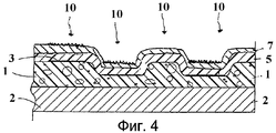
фиг.4 - фрагментарный вид в разрезе продукта, изготовленного в соответствии со способом, иллюстрированным на фиг.1, после второй стадии отверждения с применением ультрафиолетового излучения (стадия (л)).4 is a fragmentary sectional view of a product made in accordance with the method illustrated in FIG. 1, after the second curing step using ultraviolet radiation (step (l)).
Согласно фиг.1 вспениваемый слой пластика, содержащий пенообразователь, наносят на листовую основу. Полученную структуру нагревают для гелеобразования слоя пластика, не активируя пенообразователь. Затем одним из обычных способов наносят на студенистый слой пластика первую печатную краску, содержащую первый фотоинициатор, с первым узором или рисунком. Затем одним из обычных способов на студенистый слой пластика наносят вторую печатную краску, содержащую ингибитор вспучивания и второй фотоинициатор, со вторым узором или рисунком, после чего ингибитор, содержащийся во второй печатной краске, мигрирует в студенистый слой пластика под второй печатной краской. Фотоинициаторы могут быть одинаковыми или различными. Они являются преимущественно ультрафиолетовыми инициаторами, то есть фотоинициаторами, способными инициировать отверждение или сшивание полимерного материала при активации особой электромагнитной энергией в ультрафиолетовом диапазоне спектра. Ингибитор должен быть выбран таким, чтобы скорость, с которой он будет мигрировать из второй печатной краски в студенистый слой пластика, была сравнима со скоростью всего процесса создания поверхностного покрытия. Специалистам в данной области техники очевидно, что узор второй краски может быть преимущественно зазором между двумя плитками, имитирующим покрытие керамической плиткой. Однако настоящее изобретение не ограничено таким рисунком и может обеспечить изображение любого желаемого рисунка. Специалистам в данной области техники очевидно также то, что термины "первая печатная краска" и "вторая печатная краска" служат только для различения красок и не обязательно относятся к порядку, в котором их наносят на студенистый слой пластика или непосредственно на основу. При этом не подразумевается, что для достижения нужного рисунка продукта в нужных цветах имеются только две печатных краски.According to figure 1, a foamable plastic layer containing a foaming agent is applied to the sheet base. The resulting structure is heated to gel the plastic layer without activating the foaming agent. Then, in one of the usual ways, the first printing ink containing the first photoinitiator with the first pattern or pattern is applied to the gelatinous layer of plastic. Then, in one of the usual ways, a second printing ink containing a bloating inhibitor and a second photoinitiator with a second pattern or pattern is applied to the gelled plastic layer, after which the inhibitor contained in the second printing ink migrates to the gelled plastic layer under the second printing ink. Photoinitiators may be the same or different. They are predominantly ultraviolet initiators, that is, photoinitiators capable of initiating the curing or crosslinking of the polymeric material when activated with special electromagnetic energy in the ultraviolet range of the spectrum. The inhibitor should be chosen so that the speed with which it will migrate from the second printing ink to the gelatinous layer of plastic is comparable to the speed of the entire process of creating a surface coating. It will be apparent to those skilled in the art that the pattern of the second paint may advantageously be a gap between two tiles that mimics a ceramic tile coating. However, the present invention is not limited to such a pattern and can provide an image of any desired pattern. It will also be apparent to those skilled in the art that the terms "first printing ink" and "second printing ink" are used only to distinguish between inks and do not necessarily refer to the order in which they are applied to the gelatinous layer of plastic or directly to the substrate. It is not implied that to achieve the desired product pattern in the right colors, there are only two printing inks.
Затем на всю поверхность студенистого слоя пластика, включая слои первой и второй печатных красок, наносят прозрачное неотверждающееся полимерное покрытие. После этого на неотверждающееся покрытие наносят второе, отверждающееся покрытие.Then, a transparent non-curing polymer coating is applied to the entire surface of the gelatinous plastic layer, including the layers of the first and second printing inks. After that, a second, curable coating is applied to the non-curable coating.
Фотоинициаторы, содержащиеся в первой и второй печатных красках, впоследствии мигрируют в отверждающееся покрытие, нанесенное на неотверждающееся покрытие и краски. Фотоинициаторы должны быть выбраны так, чтобы скорость, с которой они будут мигрировать из печатных красок в отверждающееся покрытие, была сравнима со скоростью всего процесса создания поверхностного покрытия. Затем структуру, состоящую из основы, слоев пластика, первой и второй печатных красок, а также неотверждающегося и отверждающегося покрытий, нагревают для гелеобразования отверждающегося покрытия. Под воздействием тепла поверхность обоих покрытий размягчается, после чего оба размягченных покрытия подвергают механическому тиснению известным способом с помощью текстурированного валика. Текстурированный валик предпочтительно имитирует текстуру песка, цементного или известкового раствора, пробки, венецианской мозаики или тому подобных материалов, упомянутых выше.The photoinitiators contained in the first and second printing inks subsequently migrate to the curable coating applied to the non-curable coating and inks. Photoinitiators should be chosen so that the speed at which they migrate from printing inks to the cured coating is comparable to the speed of the entire surface coating process. Then, the structure, consisting of a base, layers of plastic, first and second printing inks, as well as non-curable and curable coatings, is heated to gel the curable coating. Under the influence of heat, the surface of both coatings softens, after which both softened coatings are subjected to mechanical embossing in a known manner using a textured roller. The textured roller preferably simulates the texture of sand, cement or lime mortar, cork, Venetian mosaics or the like materials mentioned above.
Для фиксации тисненой текстуры в участках отверждающегося покрытия, покрывающих первую и вторую печатные краски, отверждающееся покрытие помещают в камеру, где его облучают ультрафиолетовым излучением определенной энергии и волнового спектра. В результате этого ультрафиолетовые фотоинициаторы обеих красок, мигрировавших в отверждающееся покрытие, активируются, что приводит к отверждению (например, сшиванию) отверждающегося полимерного покрытия участков, покрывающих первую и вторую печатные краски.To fix the embossed texture in the areas of the curable coating covering the first and second printing inks, the cured coating is placed in a chamber where it is irradiated with ultraviolet radiation of a certain energy and wave spectrum. As a result, the ultraviolet photoinitiators of both inks migrating to the curable coating are activated, which leads to curing (for example, crosslinking) of the curable polymer coating of the areas covering the first and second printing inks.
Затем продукт помещают в термостат, где он нагревается приблизительно до 170-220°С, предпочтительно до 185-195°С. В результате этого участки отверждающегося покрытия, не покрывающие слои первой или второй печатных красок, разжижаются и сглаживаются так, что деформации отверждающегося покрытия в этих участках, обусловленные механическим тиснением с помощью текстурированного валика, исчезают, то есть сглаживаются. Кроме того, участок вспениваемого слоя пластика, не лежащий под второй печатной краской, содержащей ингибитор, вспенивается и разбухает.Then the product is placed in a thermostat, where it is heated to approximately 170-220 ° C, preferably to 185-195 ° C. As a result of this, areas of the curable coating that do not cover the layers of the first or second printing inks are liquefied and smoothed so that the deformations of the curable coating in these areas caused by mechanical embossing with a textured roller disappear, i.e., are smoothed. In addition, a portion of the foamable plastic layer that does not lie beneath the second printing ink containing the inhibitor foams and swells.
Затем продукт может быть подвергнут стадии второго механического тиснения известными способами, на которой на сглаженную поверхность отверждающегося покрытия наносят другую текстуру, такую как природный камень, древесина или тому подобное, описанное выше.The product can then be subjected to a second mechanical embossing step by known methods in which another texture, such as natural stone, wood or the like described above, is applied to the smooth surface of the cured coating.
Раствор фотоинициатора отверждения наносят на поверхность отверждающегося покрытия.The curing photoinitiator solution is applied to the surface of the curable coating.
Затем продукт помещают в другую камеру, где его облучают ультрафиолетовым излучением правильно выбранной энергии и волнового спектра для активации ультрафиолетового фотоинициатора отверждения отверждающегося покрытия, что приводит к отверждению (например, сшиванию) отверждающегося полимерного покрытия в участках, находящихся вне первой и второй печатных красок.The product is then placed in another chamber, where it is irradiated with ultraviolet radiation of the correct energy and wave spectrum to activate the ultraviolet curing photoinitiator of the cured coating, which leads to curing (e.g. crosslinking) of the cured polymer coating in areas outside the first and second printing inks.
Важной особенностью способа и продукта согласно настоящему изобретению является то, что вся поверхность продукта может быть первоначально текстурирована на первой стадии механического тиснения без применения текстурирующего валика со специальным рисунком, управляемого для обеспечения совпадения с рисунком или отделкой поверхностного покрытия. Поэтому участки поверхности отверждающегося покрытия, не зафиксированные после первой стадии механического тиснения, будут размягчены в процессе последующей обработки для расплавления и вспучивания и станут гладкими в результате тепловой релаксации благодаря способности пластика восстанавливать первоначальную форму, как указано в патенте США №3887678.An important feature of the method and product according to the present invention is that the entire surface of the product can be initially textured in the first stage of mechanical embossing without the use of a texture roller with a special pattern, controlled to match the pattern or finish of the surface coating. Therefore, surface areas of the curable coating that are not fixed after the first stage of mechanical embossing will be softened during subsequent processing for melting and expansion and will become smooth as a result of thermal relaxation due to the ability of the plastic to restore its original shape, as described in US patent No. 3887678.
Продукт, имеющий структуру, иллюстрируемую фиг.2-4, изготовлен способом, показанным на фиг.1. Как показано на фиг.2, вспениваемый слой пластика 1, содержащий пенообразователь, наносят на листовую основу 2. Затем полученную структуру нагревают для гелеобразования слоя пластика 1. Первую печатную краску 3, содержащую ультрафиолетовый фотоинициатор, и вторую печатную краску 4, содержащую ингибитор вспучивания и ультрафиолетовый фотоинициатор, наносят на студенистый слой пластика 1 в соответствии с первым и вторым рисунками.The product having the structure illustrated in FIGS. 2-4 is made by the method shown in FIG. 1. As shown in FIG. 2, a foamable
Прозрачное неотверждающееся покрытие 5 (см. фиг.3) наносят на всю поверхность гелируемого слоя пластика 1 и первой и второй печатных красок 3, 4.Transparent non-curing coating 5 (see figure 3) is applied to the entire surface of the gelable layer of
Затем на неотверждающееся покрытие 5 наносят отверждающееся покрытие 7.Then, a
После нагревания неотверждающегося 5 и отверждающегося 7 покрытий для их гелеобразования и размягчения размягченные покрытия 5, 7 подвергают первой стадии механического тиснения с помощью текстурированного валика для создания первой текстуры 8. Затем текстурированное отверждающееся покрытие подвергают облучению ультрафиолетовым излучением 9 для активации ультрафиолетовых фотоинициаторов обеих красок и таким образом отверждают ту часть (и только ту часть) отверждающегося покрытия 7, которая покрывает оба рисунка или узора красок 3, 4. Затем продукт нагревают в термостате для сглаживания участка покрытий 5, 7, не покрывающего печатные краски 3, 4, чтобы текстуры, относящиеся к первой стадии механического тиснения на этом участке, исчезли (см. фиг.4). Кроме того, участок студенистого слоя пластика 1, не содержащий ингибитора, покрытый второй печатной краской 4, вспенивается и вспучивается. Затем сглаженные участки поверхности отверждающегося покрытия могут быть подвергнуты второй стадии механического тиснения для создания второй текстуры.After heating non-curing 5 and curing 7 coatings to gel and soften them, the
На поверхность отверждающегося покрытия 7 наносят раствор отверждающего ультрафиолетового фотоинициатора (не показан).A curing ultraviolet photoinitiator solution (not shown) is applied to the surface of the
Затем продукт подвергают воздействию ультрафиолетового облучения 10 для активации отверждающего ультрафиолетового фотоинициатора и отверждения таким образом участка отверждающегося покрытия, находящегося вне печатных красок 3 и 4.The product is then exposed to
Далее каждый компонент продукта и каждая стадия способа в соответствии с изобретением описаны в отношении различных предпочтительных и альтернативных вариантов осуществления изобретения.Further, each component of the product and each stage of the method in accordance with the invention are described in relation to various preferred and alternative embodiments of the invention.
ОсноваThe basis
Основой является относительно плоский волокнистый или неволокнистый листовой материал основы, такой как волокнистый, валяный или спутанный относительно плоский лист, состоящий из пересекающихся волокон. Основа может при необходимости содержать войлок или бумагу, тканую или нетканую. Она может содержать вязаный или изготовленный иным способом текстильный материал или ткани, изготовленные из целлюлозы, стекла, натуральных или синтетических органических волокон, или натуральных или синтетических минеральных волокон, или сетки или листы на основе или без основы, изготовленные из них, или заполненные или незаполненные термопластичные или термореактивные полимерные материалы. Она может также содержать компактный или вспененный слой. Эти и другие материалы основы хорошо известны и не требуют дальнейшей детализации.The base is a relatively flat fibrous or non-fibrous sheet material of the base, such as a fibrous, felted or tangled relatively flat sheet, consisting of intersecting fibers. The base may optionally contain felt or paper, woven or non-woven. It may contain knitted or otherwise made textile material or fabrics made of cellulose, glass, natural or synthetic organic fibers, or natural or synthetic mineral fibers, or nets or sheets based on or without a basis made of them, or filled or unfilled thermoplastic or thermosetting polymeric materials. It may also contain a compact or foam layer. These and other base materials are well known and do not require further detail.
Вспениваемый слой пластикаFoamable plastic layer
Вспениваемый слой пластика, когда он используется, может состоять из любого подходящего известного материала для изготовления вспененных пластиковых слоев на основе, но обычно используется поливинилхлоридный (ПВХ) пластизоль, органозоль, полиолефин, иономер (в частности, сополимеры этилена с акриловой и/или метакриловой кислотами под торговой маркой "Iotek"), пластифицированный ПВХ или термопластичный каучук. Этот слой может быть пигментирован или лишен пигментирования. Если слой пигментирован, предпочтительно выбирать цвет, являющийся средним из цветов конечного продукта, чтобы внешний вид и эстетика продукта поддерживались в течение срока его службы. Для опытного специалиста средним цветом является цвет, воспринимаемый при наблюдении поверхности с расстояния более чем примерно пять футов (приблизительно 1,5 м).The foamable plastic layer, when used, may consist of any suitable known material for the manufacture of foam-based plastic layers based on, but usually polyvinyl chloride (PVC) plastisol, organosol, polyolefin, ionomer (in particular ethylene acrylic and / or methacrylic acid copolymers) under the brand name "Iotek"), plasticized PVC or thermoplastic rubber. This layer may be pigmented or lack pigmentation. If the layer is pigmented, it is preferable to choose a color that is the middle of the colors of the final product, so that the appearance and aesthetics of the product are maintained throughout its life. For an experienced person, the middle color is the color perceived when observing the surface from a distance of more than about five feet (about 1.5 m).
Вспениваемый слой пластика может содержать любой из различных материалов на основе смолы ПВХ, обычно используемых в сочетании с покрытием из декоративных листовых материалов, и может содержать конкретно материалы, описанные в патенте США №3458337, но не ограничиваться ими. Наряду с подходящим вспенивателем или порофором, как указано в упомянутом патенте, вместо него может использоваться смесь вспенивателей - азодикарбонамида (ABFA) и p.p'-оксибис (бензолсульфонилгидразид) (OBSH). Дополнительно могут использоваться обычные ингредиенты, такие как стабилизаторы, катализаторы вспенивателя и т.д. Конечно, требуется катализатор, если необходимо химическое ингибирование. Хотя предпочтительным вспениваемым слоем пластика является смола гомополимера ПВХ, могут использоваться другие смолы хлористого винила. Пригодны другие синтетические смолы, такие как полистирол, замещенный полистирол (в котором заместители предпочтительно выбраны из группы, состоящей из алкила, содержащего 1-10 атомов углерода, предпочтительно 1-4 атома углерода, и арила, содержащего 6-14 атомов углерода), полиолефины, такие как полиэтилен и полипропилен, акрилаты и метакрилаты, полиамид, полиэфиры и любая другая природная или синтетическая смола.The foamable plastic layer may contain any of various materials based on PVC resin, commonly used in combination with a coating of decorative sheet materials, and may specifically contain the materials described in US Pat. No. 3,545,337. Along with a suitable blowing agent or porophore, as indicated in the aforementioned patent, a mixture of blowing agents, azodicarbonamide (ABFA) and p.p'-oxybis (benzenesulfonylhydrazide) (OBSH), can be used instead. Additionally, conventional ingredients such as stabilizers, blowing agent catalysts, etc. may be used. Of course, a catalyst is required if chemical inhibition is necessary. Although the preferred foamable plastic layer is a PVC homopolymer resin, other vinyl chloride resins may be used. Other synthetic resins are suitable, such as polystyrene, substituted polystyrene (in which the substituents are preferably selected from the group consisting of alkyl containing 1-10 carbon atoms, preferably 1-4 carbon atoms, and aryl containing 6-14 carbon atoms), polyolefins such as polyethylene and polypropylene, acrylates and methacrylates, polyamide, polyesters and any other natural or synthetic resin.
Состав вспениваемого слоя пластика должна быть совместим с расположенной под ним основой и печатными красками и при гелеобразовании должен давать гладкую и однородную поверхность для первой и второй печатных красок. С другой стороны, состав должен быть также совместим со всем составом продукта и, следовательно, с принципами настоящего изобретения. Как отмечалось, несущественно, чтобы в качестве вспениваемого слоя пластика использовался именно пластизоль. Могут применяться также органозоли и водные латексы, используемые в качестве дисперсионных или суспендированных сред, органические растворители и вода, соответственно, а не пластификаторы, как в случае пластизоля.The composition of the foamable plastic layer should be compatible with the base underneath and the printing inks and, when gelled, should give a smooth and uniform surface for the first and second printing inks. On the other hand, the composition should also be compatible with the entire composition of the product and, therefore, with the principles of the present invention. As noted, it is not essential that plastisol be used as the foamable plastic layer. Organosols and aqueous latexes used as dispersion or suspended media, organic solvents and water, respectively, rather than plasticizers, as in the case of plastisol can also be used.
Вспениваемый слой пластика в значительной степени равномерно наносят в жидком состоянии на основу обычными средствами, такими как роликовая машина для нанесения покрытий, прямопрокатная машина, барабанное сито, вытягивающий барабан, обратная роликовая машина или проволоконамоточный барабан. Конкретный способ нанесения вспениваемого слоя пластика не относится к сути изобретения; может использоваться любой подходящий способ нанесения покрытия.The foamable plastic layer is substantially uniformly applied in a liquid state to the substrate by conventional means, such as a roller coating machine, a direct rolling machine, a drum sieve, a pulling drum, a reverse roller machine or a wire winding drum. A specific method for applying a foamable plastic layer is not relevant to the invention; any suitable coating method may be used.
Толщина вспениваемого жидкого слоя пластика, наносимого на поверхность основы, в значительной степени однородна и находится в диапазоне примерно 2-30 мил (примерно 50-765 мкм), предпочтительно примерно 6-16 мил (примерно 150-410 мкм). Слой может быть толще или тоньше, как может требовать конкретное применение продукта.The thickness of the expandable liquid plastic layer applied to the surface of the substrate is substantially uniform and is in the range of about 2-30 mils (about 50-765 microns), preferably about 6-16 mils (about 150-410 microns). The layer may be thicker or thinner, as the specific application of the product may require.
Вместо вспениваемого слоя пластика на основу может быть нанесен слой пластика, не содержащий вспенивателя или порофора, таким же способом, как описано выше.Instead of a foamable plastic layer, a plastic layer that does not contain a blowing agent or porophore can be applied to the substrate in the same manner as described above.
ГелеобразованиеGelation
После нанесения на основу вспениваемого жидкого слоя пластика, содержащего пенообразователь, полученную структуру нагревают в течение определенного времени при температуре, достаточной для гелеобразования слоя пластика, но не достаточной для активации или разложения порофора или пенообразователя. Это может быть сделано в термостате или на нагретом хромовом барабане. Если для стадии гелеобразования использовать термостат, то хорошие результаты будут получены при выдержке в термостате в течение примерно 0,5-3,5 мин и температуре термостата примерно 120-160°С. Если использовать хромовый барабан, то хорошие результаты будут получены при выдержке на барабане в течение примерно 8-30 с и температуре барабана примерно 110-140°С. При кратковременной выдержке используют более высокие температуры, а при более длительной выдержке - более низкие температуры. Затем слой охлаждают, чтобы сделать поверхность пригодной для печати. Охлаждение обычно осуществляют посредством контакта поверхности вспениваемого студенистого слоя пластика (и иногда нижней стороны основы) с одним или более охлаждающими барабанами. В барабанах может циркулировать обычная или охлажденная вода. Охлаждение может быть интенсифицировано с помощью вентиляторов или воздуходувок. Такой же процесс гелеобразования может быть использован, если слой пластика не содержит вспенивателя или порофора, что будет видно специалисту. Для создания слоя, пригодного для печати, могут быть использованы также способы каландрования или экструзии с последующим ламинированием основы или листа, состоящих из материалов, подобных описанным выше.After applying a foaming liquid plastic layer containing a foaming agent to the base, the resulting structure is heated for a certain time at a temperature sufficient to gel the plastic layer, but not sufficient to activate or decompose the porophore or foaming agent. This can be done in a thermostat or on a heated chrome drum. If a thermostat is used for the gelation stage, good results will be obtained by holding in a thermostat for about 0.5-3.5 minutes and a thermostat temperature of about 120-160 ° C. If you use a chrome drum, good results will be obtained by holding on the drum for about 8-30 s and a drum temperature of about 110-140 ° C. For short exposure, higher temperatures are used, and for longer exposure lower temperatures are used. The layer is then cooled to make the surface suitable for printing. Cooling is usually carried out by contacting the surface of the expandable gelatinous layer of plastic (and sometimes the underside of the base) with one or more cooling drums. Regular or chilled water can circulate in the drums. Cooling can be intensified by fans or blowers. The same gelation process can be used if the plastic layer does not contain a blowing agent or porophore, which will be apparent to the skilled person. To create a printable layer, calendering or extrusion methods can also be used followed by lamination of a substrate or sheet consisting of materials similar to those described above.
Печатные краскиInks
В предшествующем предпочтительном варианте осуществления изобретения первую печатную краску, содержащую фотоинициатор, наносят с первым рисунком или узором на студенистый слой пластика. Затем на студенистый слой пластика наносят вторую печатную краску, содержащую фотоинициатор и ингибитор вспучивания со вторым рисунком или узором. Подходящими печатными красками являются обычно используемые при нанесении поверхностных покрытий. Они содержат пластизоль, составы на основе растворителей и воды. Конечно, в дополнение к первой и второй печатным краскам для достижения целей дизайна могут быть использованы другие печатные краски, не содержащие фотоинициатора или ингибитора вспучивания. Кроме того, не требуется использовать и первую и вторую печатные краски, если используется, по меньшей мере, одна печатная краска с фотоинициатором. Или краска может использоваться одна или в сочетании с другими печатными красками, не содержащими фотоинициатора или ингибитора вспучивания. Если вспениваемый слой пластика не используется, краски, имеющие ингибитор вспучивания, не используют.In a previous preferred embodiment of the invention, a first printing ink containing a photoinitiator is applied with a first pattern or pattern onto the gelatinous layer of plastic. Then, a second printing ink containing a photoinitiator and an expansion inhibitor with a second pattern or pattern is applied to the gelatinous layer of plastic. Suitable printing inks are commonly used for applying surface coatings. They contain plastisol, solvent and water based formulations. Of course, in addition to the first and second printing inks, other printing inks not containing a photoinitiator or an expansion inhibitor can be used to achieve design goals. In addition, it is not required to use both the first and second printing inks if at least one printing ink with a photoinitiator is used. Or, the ink can be used alone or in combination with other printing inks that do not contain a photoinitiator or an expansion inhibitor. If a foamable plastic layer is not used, paints having an expansion inhibitor are not used.
Первая, вторая и другие печатные краски могут быть пигментированными или непигментированными и могут содержать органические пигменты или частицы неорганического пигмента, такого как диоксид титана, оксид железа, сажа, слюда, перламутр и т.п. Декоративные отражающие частицы, такие как металлические, также могут содержаться как часть одной или более композиций печатной краски. Типы и компоненты первой, второй и других печатных красок могут быть одинаковыми или различными.The first, second and other printing inks may be pigmented or non-pigmented and may contain organic pigments or particles of an inorganic pigment such as titanium dioxide, iron oxide, carbon black, mica, mother of pearl and the like. Decorative reflective particles, such as metal, may also be contained as part of one or more ink compositions. The types and components of the first, second, and other printing inks may be the same or different.
Первая и вторая печатные краски содержат фотоинициатор. Только в виде примера, но не в качестве ограничения укажем, что в соответствии с настоящим изобретением могут быть использованы следующие сшивающие ультрафиолетовые инициаторы: бензофенон, 2-хлоротиоксантон, 2-метилтиоксантон, 2-изопропилтиоксантон, бензоин, 4,4'-диметоксибензоин, этиловый эфир бензоина, изопропиловый эфир бензоина, бензилдиметилкетал, 1,1,1-трихлороацетофенон, 1-фенил-1,2-пропанедион-2-(этоксикарбонил)-оксид, диэтоксиацетофенон и дибензосуберон. Краски, содержащие фотоинициаторы, должны содержать фотоинициатор в концентрации примерно 1-15 процентов по массе, предпочтительно примерно 10 процентов по массе.The first and second printing inks contain a photoinitiator. By way of example only, and not by way of limitation, we indicate that the following crosslinking ultraviolet initiators can be used in accordance with the present invention: benzophenone, 2-chlorothioxantone, 2-methylthioxantone, 2-isopropylthioxantone, benzoin, 4,4'-dimethoxybenzoin, ethyl benzoin ether, benzoin isopropyl ether, benzyldimethyl ketal, 1,1,1-trichloroacetophenone, 1-phenyl-1,2-propanedione-2- (ethoxycarbonyl) oxide, diethoxyacetophenone and dibenzosuberone. Paints containing photoinitiators should contain a photoinitiator in a concentration of about 1-15 percent by weight, preferably about 10 percent by weight.
Вторая печатная краска содержит также ингибитор вспучивания. Только с целью примера, а не в качестве ограничения, укажем, что в соответствии с настоящим изобретением могут быть использованы следующие ингибиторы: бензотриазол, толилтриазол, фумаровая кислота и тримеллитовый ангидрид. Конкретный используемый ингибитор вспучивания не относится к сути настоящего изобретения, и для рядового специалиста доступны многие другие подходящие и приемлемые ингибиторы вспучивания.The second ink also contains an expansion inhibitor. For the purpose of example only, and not by way of limitation, we indicate that the following inhibitors can be used in accordance with the present invention: benzotriazole, tolyltriazole, fumaric acid and trimellitic anhydride. The particular expansion inhibitor used is not essential to the present invention, and many other suitable and acceptable expansion inhibitors are available to those skilled in the art.
Печать красок на студенистом слое пластика может быть выполнена способами ротационной глубокой печати, флексографской печати, трафаретной печати, прижимной или накатной печати или другими способами печати, обычно используемыми при создании продуктов для обшивки стен или пола.Printing inks on the gelatinous layer of plastic can be done by rotogravure printing, flexographic printing, screen printing, press or roll printing or other printing methods commonly used to create products for wall or floor sheathing.
После нанесения на студенистый слой пластика второй печатной краски ингибитор, содержащийся во второй печатной краске, мигрирует в студенистый слой пластика под второй печатной краской.After applying a second printing ink to the gelatinous plastic layer, the inhibitor contained in the second printing ink migrates to the gelatinous plastic layer under the second ink.
Специалистам в данной области техники очевидно, что в настоящем изобретении для печати рисунков или узоров на основе или на студенистом слое пластика могут быть использованы одна краска, две краски или много красок. Каждая краска может по выбору содержать фотоинициатор и/или ингибитор. Конечно, для достижения целей дизайна может использоваться краска без фотоинициаторов или ингибиторов. Специалистам в данной области техники очевидно также, что порядок печати неважен и не должен рассматриваться как ограничение изобретения. Кроме того, следует понимать, что участки печати красок могут перекрываться.It will be apparent to those skilled in the art that in the present invention, one ink, two inks, or many inks can be used to print patterns or patterns based on or on a gelatinous layer of plastic. Each paint may optionally contain a photoinitiator and / or inhibitor. Of course, paint without photoinitiators or inhibitors can be used to achieve design goals. It will also be apparent to those skilled in the art that the printing order is unimportant and should not be construed as limiting the invention. In addition, it should be understood that the printing areas of the inks may overlap.
Неотверждающееся покрытиеNon-curing coating
После нанесения печатных красок на всю поверхность студенистого слоя пластика, включая покрытую первой и второй печатными красками, наносят жидкое неотверждающееся покрытие.After printing inks are applied to the entire surface of the gelatinous plastic layer, including coated with the first and second printing inks, a liquid non-curing coating is applied.
Толщина неотверждающегося покрытия, нанесенного в жидком липком неотвержденном состоянии на студенистый слой пластика и краску, в значительной степени однородна и находится в диапазоне примерно 80-400 мкм, предпочтительно примерно 100-250 мкм. Покрытие может быть тоньше или толще, как может требоваться конкретным применением продукта. Неотверждающееся покрытие наносят обычным способом, таким как описанный выше в отношении нанесения вспениваемого слоя пластика. Конкретный способ нанесения неотверждающегося покрытия не относится к сути изобретения; может быть использован любой подходящий способ нанесения покрытия.The thickness of the non-curing coating applied in a sticky liquid non-cured state to the gelatinous layer of plastic and paint is substantially uniform and is in the range of about 80-400 microns, preferably about 100-250 microns. The coating may be thinner or thicker, as may be required by the specific application of the product. The non-curable coating is applied in a conventional manner, such as described above with respect to the application of a foamable plastic layer. A specific method for applying a non-curable coating is not relevant to the invention; any suitable coating method may be used.
В конкретном случае состав неотверждающегося покрытия может включать, например, пластизоль или органозоль.In a particular case, the composition of the non-curable coating may include, for example, plastisol or organosol.
Пластизоль представляет собой жидкую композицию, включающую ПВХ, пластификатор, стабилизатор, наполнитель и технологические добавки. В таблице 1 приведен пример конкретного состава пластизоля, который может быть использован в настоящем изобретении.Plastisol is a liquid composition comprising PVC, plasticizer, stabilizer, filler and processing aids. Table 1 shows an example of a specific plastisol composition that can be used in the present invention.
- Lacovyl 1704PVC
- Lacovyl 1704
- CA/ZnStabilizer
- CA /
- САСО3 Filler
- CASO 3
- азодикарбонамидTechnological Additives
- azodicarbonamide
Органозоль представляет собой жидкую композицию, такую как пластизоль, но в которой вместо пластификаторов используются ПВХ-растворители, в частности хлоргидрокарбонаты или ацетон.An organosol is a liquid composition, such as plastisol, but in which PVC solvents, in particular chlorohydrocarbonates or acetone, are used instead of plasticizers.
Неотверждающееся покрытие является предпочтительно прозрачным, но оно может быть окрашено до полупрозрачного состояния при условии пропускания электромагнитного (предпочтительно ультрафиолетового) излучения. Неотверждающееся покрытие может также содержать твердые макрочастицы, такие как осколки, хлопья и т.д.The non-curable coating is preferably transparent, but it can be colored to a translucent state provided that electromagnetic (preferably ultraviolet) radiation is transmitted. The non-curable coating may also contain solid particulate matter such as chips, flakes, etc.
Это неотверждающееся покрытие по существу не содержит инициатора теплового отверждения, сшивания или полимеризации. В предпочтительном варианте осуществления изобретения фотоинициаторы, содержащиеся в первой и второй печатных красках, затем мигрируют через участок неотверждающегося слоя, который был нанесен на первую и вторую печатные краски в отверждающемся покрытии, нанесенном ранее. Неотверждающееся покрытие скрепляют с печатным студенистым слоем пластика любым известным подходящим способом, например раскаткой.This non-curable coating essentially does not contain an initiator of thermal curing, crosslinking or polymerization. In a preferred embodiment, the photoinitiators contained in the first and second printing inks then migrate through a portion of the uncured layer that has been applied to the first and second printing inks in the previously cured coating. The non-curable coating is bonded to the printed gelatinous layer of plastic by any known suitable method, for example, by rolling.
Отверждающееся покрытиеCuring coating
В способе согласно изобретению отверждающееся покрытие наносят на неотверждающееся покрытие. В предпочтительном варианте отверждающееся покрытие содержит полимеры уретанового типа и, в частности, состоит в основном из полиуретана. Указанные полимеры характеризуются такими особенностями, как физическое высушивание и термическое и/или ультрафиолетовое отверждение. В таблице 2 приведен пример конкретного состава отверждающегося покрытия, который может быть использован в настоящем изобретении.In the method according to the invention, a curable coating is applied to a non-curable coating. In a preferred embodiment, the curable coating comprises urethane-type polymers and, in particular, consists mainly of polyurethane. These polymers are characterized by features such as physical drying and thermal and / or ultraviolet curing. Table 2 shows an example of a specific curable coating composition that can be used in the present invention.

Кроме отверждающегося покрытия на основе полиуретанов в изобретении могут использоваться и другие, в частности, содержащие полимеры простых эфиров акрилатов или полимеры сложных эфиров акрилатов, например Ebecryl 80 или Ebecryl 851.In addition to a polyurethane-based curable coating, others can be used in the invention, in particular those containing acrylate ether polymers or acrylate ester polymers, for example Ebecryl 80 or Ebecryl 851.
Как было упомянуто выше, на отверждающееся покрытие после стадии (з), в частности стадии (и), может быть нанесен второй жидкий фотоинициатор. В таблице 3 приведен пример конкретного состава такого жидкого фотоинициатора, который может быть использован в настоящем изобретении.As mentioned above, a second liquid photoinitiator can be applied to the cured coating after step (h), in particular step (s). Table 3 shows an example of a specific composition of such a liquid photoinitiator that can be used in the present invention.
Стадия нагревания и первого тисненияStage of heating and first embossing
Для подготовки к механическому тиснению и отверждающееся, и неотверждающееся покрытия размягчают нагреванием. Продукт помещают в термостат, в котором поддерживают температуру примерно 100-160°С, предпочтительно примерно 130-140°С, примерно на 1-5 мин. Обычно используют термостат с рециркуляцией горячего воздуха и/или инфракрасный (ИК) термостат, обеспечивающий указанный диапазон температур. Затем поверхность продукта размягчают теплом, предпочтительно с помощью ИК термостата при температуре примерно 120-190°С, предпочтительно 150-170°С, измеряя ее пирометром перед прижимом валиков для тиснения.To prepare for mechanical embossing, both cured and non-cured coatings are softened by heating. The product is placed in a thermostat in which a temperature of about 100-160 ° C., preferably about 130-140 ° C., is maintained for about 1-5 minutes. Typically, a thermostat with recirculation of hot air and / or an infrared (IR) thermostat providing the indicated temperature range is used. Then the surface of the product is softened with heat, preferably using an IR thermostat at a temperature of about 120-190 ° C, preferably 150-170 ° C, measuring it with a pyrometer before pressing the embossing rollers.
После надлежащего размягчения покрытий их подвергают механическому тиснению с помощью текстурированного барабана, имитирующего текстуру песка, цементного или известкового раствора или подобного описанному выше. Текстурированный барабан функционирует под давлением, зависящим от необходимой степени текстурирования, известной специалисту средней квалификации.After proper softening of the coatings, they are mechanically embossed using a textured drum that simulates the texture of sand, cement or lime mortar or the like described above. A textured drum operates under pressure, depending on the required degree of texturing, known to a specialist of average skill.
Первое ультрафиолетовое (УФ) отверждениеThe first ultraviolet (UV) cure
Перед отверждением с помощью ультрафиолетового излучения продукт может быть охлажден. Это не обязательно, но желательно для ослабления испарения в ультрафиолетовой камере, которое может приводить к ослаблению воздействия на продукт ультрафиолетового излучения. По завершении первой стадии тиснения продукт помешают в камеру, где его подвергают облучению ультрафиолетовой лампой для отверждения участков отверждающегося покрытия, покрывающего первую и вторую печатные краски, содержащие фотоинициатор. На этой стадии происходит фиксация тисненой текстуры на участках поверхности покрытия, расположенных поверх краски, содержащей фотоинициатор.Before curing with ultraviolet radiation, the product can be cooled. This is not necessary, but it is desirable to attenuate evaporation in the ultraviolet chamber, which may lead to a weakening of the effect of ultraviolet radiation on the product. Upon completion of the first embossing step, the product is placed in a chamber where it is irradiated with an ultraviolet lamp to cure sections of the curable coating covering the first and second printing inks containing a photoinitiator. At this stage, the embossed texture is fixed on the surface areas of the coating located on top of the paint containing the photoinitiator.
Отверждение под воздействием ультрафиолетового излучения может быть выполнено в ультрафиолетовом реакторе, где продукт подвергают воздействию излучения регулируемой мощности с энергетической экспозицией приблизительно 10-150 мДж/см2, предпочтительно около 30 мДж/см2, при спектральной плотности потока излучения по длине волны приблизительно 20-160 Вт/см с использованием ламп Н-, V- или D-типа, предпочтительно ламп Н-типа.Curing under the influence of ultraviolet radiation can be performed in an ultraviolet reactor, where the product is exposed to radiation of controlled power with an energy exposure of about 10-150 mJ / cm 2 , preferably about 30 mJ / cm 2 , with a spectral radiation flux density of about 20- 160 W / cm using H-, V- or D-type lamps, preferably H-type lamps.
Сплавление и вспучиваниеFusion and expansion
После отверждения участков отверждающегося покрытия в вышеописанной камере извлеченный из нее продукт помещают в термостат, в котором поддерживают температуру примерно 170-220°C, предпочтительно около 190°С. Продукт выдерживают в термостате примерно 0,5-3 мин. Обычно используют термостат с рециркуляцией горячего воздуха и/или ИК термостат, функционирующий при этих температурах.After the curing of the areas of curable coating in the above-described chamber, the product extracted from it is placed in a thermostat in which a temperature of about 170-220 ° C, preferably about 190 ° C, is maintained. The product is kept in a thermostat for about 0.5-3 minutes. Typically, a thermostat with recirculation of hot air and / or an IR thermostat operating at these temperatures is used.
В процессе выдержки продукта при указанных температурах в течение указанного периода времени происходит сплавление основы, слоя пластика, слоев печатных красок и покрытия, а также вспенивание и вспучивание частей вспениваемого слоя пластика, не лежащих под второй печатной краской, содержащей ингибитор. Кроме того, части (то есть участки поверхности) отверждающегося покрытия, которые не были ранее отверждены, то есть не покрывают первую или вторую печатные краски, сглаживают так, что деформация и текстурирование в еще отверждающемся покрытии в этих участках, выполненная на стадии первого механического тиснения на этих участках, исчезает, то есть сглаживается. Более конкретно, в процессе выполнения этой стадии часть отверждающегося покрытия, не отвержденная (не сшитая) в процессе облучения ультрафиолетовым излучением, подвергается релаксации, имеющей эффект сглаживания текстурированной поверхности, в то время как часть отверждающегося покрытия, которая была отверждена в процессе отверждения под воздействием ультрафиолетового излучения, сохраняет текстурированный внешний вид. Это явление сглаживания требует проведения полного первого тиснения, выполняемого при как можно более низкой температуре, чтобы минимизировать механическую деформацию пластиковых компонентов, обусловленную воздействием на отверждающееся покрытие валика для тиснения.In the process of exposure of the product at the indicated temperatures during the specified period of time, the base, plastic layer, layers of printing inks and coatings are fused, as well as foaming and swelling of parts of the foamable plastic layer that do not lie under the second printing ink containing the inhibitor. In addition, parts (i.e., surface areas) of the curable coating that have not previously been cured, that is, do not cover the first or second printing inks, are smoothed so that the deformation and texturing in the still curing coating in these areas is carried out in the first mechanical embossing step in these areas, it disappears, that is, is smoothed out. More specifically, during this step, a portion of the curable coating that is not cured (not crosslinked) by UV irradiation undergoes relaxation, which has the effect of smoothing the textured surface, while a portion of the cured coating that was cured during curing by UV radiation, maintains a textured appearance. This smoothing phenomenon requires a complete first embossing, carried out at the lowest possible temperature, in order to minimize the mechanical deformation of the plastic components due to the effect of the embossing roller on the cured coating.
Вторая стадия тиснения (необязательно)Second embossing step (optional)
После извлечения из термостата части отверждающегося покрытия (теперь отвержденного покрытия), не покрывающие печатные краски и, следовательно, сглаженные, подвергают механическому тиснению во второй раз известным способом, таким как обработка текстурированным роликом или другим обычным средством, имеющим текстуру, подобную натуральной текстуре камня, древесины или тому подобного, как описано выше.After removing from the thermostat parts of the cured coating (now cured coating) that are not coated with printing inks and therefore smoothened, are subjected to mechanical embossing a second time in a known manner, such as treating with a textured roller or other conventional means having a texture similar to the natural texture of the stone, wood or the like as described above.
Второе отверждение под воздействием ультрафиолетового (УФ) излученияThe second cure under the influence of ultraviolet (UV) radiation
Продукт со стадии сплавления (или, необязательно, второй стадии тиснения) перед проведением отверждения ультрафиолетовым излучением может быть охлажден по причинам, изложенным выше применительно к первому отверждению ультрафиолетовым излучением. Затем продукт помещают в камеру, где его подвергают облучению излучением ультрафиолетовой лампы для сшивания части отверждающегося покрытия, покрывающего участки, не подвергавшиеся печати. Эта стадия обеспечивает фиксацию тисненой текстуры в этих участках поверхности покрытия.The product from the fusion step (or, optionally, the second embossing step) may be chilled prior to UV curing for the reasons set forth above with respect to the first UV cure. The product is then placed in a chamber where it is irradiated with an ultraviolet lamp to crosslink a portion of the curable coating covering the unprinted areas. This stage fixes the embossed texture in these areas of the coating surface.
Отверждение под воздействием ультрафиолетового излучения может быть выполнено в ультрафиолетовом реакторе, где продукт подвергают воздействию сфокусированного или диффузного ультрафиолетового излучения, предпочтительно сфокусированного излучения регулируемой мощности с энергетической экспозицией примерно 400-1000 мДж/см2, предпочтительно примерно 600 мДж/см2, при спектральной плотности потока излучения по длине волны приблизительно 200-600 мВт/см с использованием ламп Н-, V- или D-типа, предпочтительно ламп Н-типа. Такой ультрафиолетовый реактор может быть приобретен у фирмы lST (Германия).UV curing can be carried out in an ultraviolet reactor, where the product is exposed to focused or diffuse ultraviolet radiation, preferably focused radiation of controlled power with an energy exposure of about 400-1000 mJ / cm 2 , preferably about 600 mJ / cm 2 , at a spectral density a radiation flux at a wavelength of about 200-600 mW / cm using H-, V- or D-type lamps, preferably H-type lamps. Such an ultraviolet reactor can be purchased from lST (Germany).
Использование каландрованных или экструдированных слоевUse of calendered or extruded layers
Как отмечено выше, вместо любого или обоих вспениваемых слоев и/или отверждающегося слоя могут быть использованы в качестве слоев каландрованные или экструдированные листы. При использовании вспениваемого листа он формируется каландрованием или экструзионной головкой при температуре ниже температуры разложения вспенивателя или порофора или катализированного вспенивателя или порофора. Когда вместо отверждающегося слоя используется лист, он обрабатывается каландрованием или экструзионной головкой в условиях, при которых пероксид существенно не разлагается, так что он остается в отверждающемся слое. Когда используются листовые материалы, их накатывают на поверхность продукта, используя известные способы. В таблице 4 приведен пример состава такого листа, который может быть использован в настоящем изобретении.As noted above, instead of any or both of the foamable layers and / or the curable layer, calendered or extruded sheets can be used as layers. When using a foamable sheet, it is formed by calendaring or by an extrusion head at a temperature below the decomposition temperature of the blowing agent or porophore or catalyzed blowing agent or porophore. When a sheet is used instead of a curable layer, it is processed by calendering or an extrusion die under conditions where the peroxide does not substantially decompose, so that it remains in the curable layer. When sheet materials are used, they are rolled onto the surface of the product using known methods. Table 4 shows an example of the composition of such a sheet that can be used in the present invention.
- Solvic 262PVC
- Solvic 262
- DINPPlasticizer
- DINP
- Ba/ZnStabilizer
- Ba / Zn
- СаСо3 Filler
- CaCO 3
Claims (25)
Applications Claiming Priority (2)
| Application Number | Priority Date | Filing Date | Title |
|---|---|---|---|
| EP03101984A EP1493861A1 (en) | 2003-07-02 | 2003-07-02 | Selectively embossed surface coverings and processes of manufacture |
| EP03101984.7 | 2003-07-02 |
Publications (2)
| Publication Number | Publication Date |
|---|---|
| RU2006102871A RU2006102871A (en) | 2006-08-27 |
| RU2310704C2 true RU2310704C2 (en) | 2007-11-20 |
Family
ID=33427231
Family Applications (1)
| Application Number | Title | Priority Date | Filing Date |
|---|---|---|---|
| RU2006102871/04A RU2310704C2 (en) | 2003-07-02 | 2004-06-29 | Surface covering with selectively formed embossment and method for manufacturing the same |
Country Status (7)
| Country | Link |
|---|---|
| US (1) | US20060159891A1 (en) |
| EP (2) | EP1493861A1 (en) |
| CA (1) | CA2530791C (en) |
| RS (1) | RS53427B (en) |
| RU (1) | RU2310704C2 (en) |
| UA (1) | UA82531C2 (en) |
| WO (1) | WO2005005713A1 (en) |
Cited By (5)
| Publication number | Priority date | Publication date | Assignee | Title |
|---|---|---|---|---|
| RU2505560C2 (en) * | 2009-06-09 | 2014-01-27 | Таркетт Г.Д.Л. С.А. | Multilayer surface coating with foamed supporting layer |
| RU2619711C2 (en) * | 2012-06-26 | 2017-05-17 | Сан Шян Текнолоджи Ко., Лтд. | Manufacture method of nonwoven composite laminated product with different hardness degree |
| RU2669612C2 (en) * | 2014-04-18 | 2018-10-12 | Таркетт Гдл | Polyurethane coating, which is cured using the actinic radiation for decorative lining coatings |
| RU2678053C2 (en) * | 2014-04-18 | 2019-01-22 | Таркетт Гдл | Actinic radiation cured polyurethane coating for decorative surface coverings |
| US20210310188A1 (en) * | 2018-11-29 | 2021-10-07 | Hewlett-Packard Development Company, L.P. | Textile printing |
Families Citing this family (8)
| Publication number | Priority date | Publication date | Assignee | Title |
|---|---|---|---|---|
| EP2221190A1 (en) | 2009-02-23 | 2010-08-25 | Tarkett GDL | Flooring |
| BE1019501A5 (en) * | 2010-05-10 | 2012-08-07 | Flooring Ind Ltd Sarl | FLOOR PANEL AND METHOD FOR MANUFACTURING FLOOR PANELS. |
| US8950147B2 (en) * | 2011-08-22 | 2015-02-10 | Awi Licensing Company | Floor panel and floating floor system incorporating the same |
| RU2748351C2 (en) * | 2016-07-18 | 2021-05-24 | БОЛЬЁ ИНТЕРНЕШЕНЛ ГРУП ЭнВи | Multi-layer sheet, suitable for use as floor or wall covering, characterized by three-dimensional relief and decorative pattern |
| US10544595B2 (en) * | 2016-08-26 | 2020-01-28 | Quickstyle Industries Inc. | Tile with protected imitation grout line |
| US10233656B2 (en) * | 2016-08-26 | 2019-03-19 | Quickstyle Industries Inc. | Densified foam core (DFC) tile with imitation grout line |
| US9938726B2 (en) | 2016-08-26 | 2018-04-10 | Quickstyle Industries Inc. | Densified foam core (DFC) tile with imitation grout line |
| US10132088B2 (en) | 2016-08-26 | 2018-11-20 | Quickstyle Industries Inc. | Stone plastic composite (SPC) tile with imitation grout line |
Family Cites Families (8)
| Publication number | Priority date | Publication date | Assignee | Title |
|---|---|---|---|---|
| US3887678A (en) | 1972-12-15 | 1975-06-03 | Armstrong Cork Co | Mechanically embossed resilient laminar floor material |
| US4298646A (en) * | 1980-06-30 | 1981-11-03 | Congoleum Corporation | Differential gloss products and methods of making the same |
| US4491616A (en) * | 1982-05-28 | 1985-01-01 | Congoleum Corporation | Resinous polymer sheet material having surface decorative effects of contrasting gloss and method of making the same |
| NO164646C (en) * | 1983-04-25 | 1990-10-31 | Eurofloor Sa | PROCEDURE FOR INCLUDING MATT AND GLOSSARY ZONES ON A SYNTHETIC COAT. |
| US4863782A (en) * | 1986-06-12 | 1989-09-05 | Mannington Mills, Inc. | Decorative embossed surface coverings having platey material and inlaid appearance |
| US7014802B1 (en) * | 1997-02-20 | 2006-03-21 | Mannington Mills, Of Delaware, Inc. | Methods to make a surface covering having a natural appearance |
| CZ2004790A3 (en) * | 2002-01-11 | 2004-10-13 | Tarkettáinc | Selectively embossed surface covering and process for producing thereof |
| US7081291B2 (en) * | 2002-01-11 | 2006-07-25 | Domco Tarkett Inc. | Selectively embossed surface coverings and processes of manufacture |
-
2003
- 2003-07-02 EP EP03101984A patent/EP1493861A1/en not_active Withdrawn
-
2004
- 2004-06-29 RU RU2006102871/04A patent/RU2310704C2/en not_active IP Right Cessation
- 2004-06-29 UA UAA200600831A patent/UA82531C2/en unknown
- 2004-06-29 RS YU20050962A patent/RS53427B/en unknown
- 2004-06-29 EP EP04741918.9A patent/EP1639193B1/en active Active
- 2004-06-29 CA CA2530791A patent/CA2530791C/en not_active Expired - Fee Related
- 2004-06-29 WO PCT/EP2004/051286 patent/WO2005005713A1/en active Application Filing
- 2004-06-29 US US10/563,145 patent/US20060159891A1/en not_active Abandoned
Cited By (5)
| Publication number | Priority date | Publication date | Assignee | Title |
|---|---|---|---|---|
| RU2505560C2 (en) * | 2009-06-09 | 2014-01-27 | Таркетт Г.Д.Л. С.А. | Multilayer surface coating with foamed supporting layer |
| RU2619711C2 (en) * | 2012-06-26 | 2017-05-17 | Сан Шян Текнолоджи Ко., Лтд. | Manufacture method of nonwoven composite laminated product with different hardness degree |
| RU2669612C2 (en) * | 2014-04-18 | 2018-10-12 | Таркетт Гдл | Polyurethane coating, which is cured using the actinic radiation for decorative lining coatings |
| RU2678053C2 (en) * | 2014-04-18 | 2019-01-22 | Таркетт Гдл | Actinic radiation cured polyurethane coating for decorative surface coverings |
| US20210310188A1 (en) * | 2018-11-29 | 2021-10-07 | Hewlett-Packard Development Company, L.P. | Textile printing |
Also Published As
| Publication number | Publication date |
|---|---|
| UA82531C2 (en) | 2008-04-25 |
| EP1639193A1 (en) | 2006-03-29 |
| RU2006102871A (en) | 2006-08-27 |
| EP1493861A1 (en) | 2005-01-05 |
| RS53427B (en) | 2014-12-31 |
| EP1639193B1 (en) | 2017-08-16 |
| CA2530791C (en) | 2012-02-21 |
| CA2530791A1 (en) | 2005-01-20 |
| WO2005005713A1 (en) | 2005-01-20 |
| RS20050962A (en) | 2006-12-15 |
| US20060159891A1 (en) | 2006-07-20 |
Similar Documents
| Publication | Publication Date | Title |
|---|---|---|
| US7081291B2 (en) | Selectively embossed surface coverings and processes of manufacture | |
| US6746756B2 (en) | Polyurethane coated resilient surface covering having improved fidelity of texture and process of manufacture | |
| RU2310704C2 (en) | Surface covering with selectively formed embossment and method for manufacturing the same | |
| US20080305311A1 (en) | Coated free-standing film | |
| RU2286883C2 (en) | Selectively stamped surface coating (versions) and the method of its manufacture (versions) | |
| CA1094439A (en) | Embossed sheet type covering material | |
| JPH01110123A (en) | Production of foamed decorative material | |
| JP2001079974A (en) | Ink jet printing medium for embossing processed interim material | |
| US6946185B2 (en) | Use of collapsible microspheres to create texture in surface coverings | |
| JPH1076587A (en) | Foamed sheet | |
| KR20030040694A (en) | PVC Flooring with sublimation-transcription-method and fiber pile and the method for the same | |
| JP3302241B2 (en) | Interior material and method of manufacturing the same | |
| JPS6039544B2 (en) | Manufacturing method of highly foamed synthetic resin molded sheet | |
| JPS5863424A (en) | Manufacture of foaming decorative laminated sheet | |
| JP2001293837A (en) | Decorative material and producing method for the same | |
| JPH01259935A (en) | Manufacture of foam decorative sheet | |
| JPH091767A (en) | Decorative material and manufacture thereof | |
| JPS5850180B2 (en) | Manufacturing method for decorative building materials | |
| JPH01275200A (en) | Manufacture of decorative material | |
| JPS61144400A (en) | Manufacture of tuned embossed sheet |
Legal Events
| Date | Code | Title | Description |
|---|---|---|---|
| MM4A | The patent is invalid due to non-payment of fees |
Effective date: 20180630 |