RU2307732C2 - Method for moving logs in cutting-off machine tools and apparatus for performing the same - Google Patents
Method for moving logs in cutting-off machine tools and apparatus for performing the same Download PDFInfo
- Publication number
- RU2307732C2 RU2307732C2 RU2005136427A RU2005136427A RU2307732C2 RU 2307732 C2 RU2307732 C2 RU 2307732C2 RU 2005136427 A RU2005136427 A RU 2005136427A RU 2005136427 A RU2005136427 A RU 2005136427A RU 2307732 C2 RU2307732 C2 RU 2307732C2
- Authority
- RU
- Russia
- Prior art keywords
- decks
- cutting
- pushing
- platform
- logs
- Prior art date
Links
Images
Classifications
-
- B—PERFORMING OPERATIONS; TRANSPORTING
- B26—HAND CUTTING TOOLS; CUTTING; SEVERING
- B26D—CUTTING; DETAILS COMMON TO MACHINES FOR PERFORATING, PUNCHING, CUTTING-OUT, STAMPING-OUT OR SEVERING
- B26D7/00—Details of apparatus for cutting, cutting-out, stamping-out, punching, perforating, or severing by means other than cutting
- B26D7/06—Arrangements for feeding or delivering work of other than sheet, web, or filamentary form
- B26D7/0608—Arrangements for feeding or delivering work of other than sheet, web, or filamentary form by pushers
-
- B—PERFORMING OPERATIONS; TRANSPORTING
- B26—HAND CUTTING TOOLS; CUTTING; SEVERING
- B26D—CUTTING; DETAILS COMMON TO MACHINES FOR PERFORATING, PUNCHING, CUTTING-OUT, STAMPING-OUT OR SEVERING
- B26D3/00—Cutting work characterised by the nature of the cut made; Apparatus therefor
- B26D3/16—Cutting rods or tubes transversely
- B26D3/161—Cutting rods or tubes transversely for obtaining more than one product at a time
-
- B—PERFORMING OPERATIONS; TRANSPORTING
- B26—HAND CUTTING TOOLS; CUTTING; SEVERING
- B26D—CUTTING; DETAILS COMMON TO MACHINES FOR PERFORATING, PUNCHING, CUTTING-OUT, STAMPING-OUT OR SEVERING
- B26D7/00—Details of apparatus for cutting, cutting-out, stamping-out, punching, perforating, or severing by means other than cutting
- B26D7/01—Means for holding or positioning work
- B26D7/02—Means for holding or positioning work with clamping means
-
- B—PERFORMING OPERATIONS; TRANSPORTING
- B26—HAND CUTTING TOOLS; CUTTING; SEVERING
- B26D—CUTTING; DETAILS COMMON TO MACHINES FOR PERFORATING, PUNCHING, CUTTING-OUT, STAMPING-OUT OR SEVERING
- B26D7/00—Details of apparatus for cutting, cutting-out, stamping-out, punching, perforating, or severing by means other than cutting
- B26D7/06—Arrangements for feeding or delivering work of other than sheet, web, or filamentary form
- B26D7/0625—Arrangements for feeding or delivering work of other than sheet, web, or filamentary form by endless conveyors, e.g. belts
-
- B—PERFORMING OPERATIONS; TRANSPORTING
- B26—HAND CUTTING TOOLS; CUTTING; SEVERING
- B26D—CUTTING; DETAILS COMMON TO MACHINES FOR PERFORATING, PUNCHING, CUTTING-OUT, STAMPING-OUT OR SEVERING
- B26D7/00—Details of apparatus for cutting, cutting-out, stamping-out, punching, perforating, or severing by means other than cutting
- B26D7/06—Arrangements for feeding or delivering work of other than sheet, web, or filamentary form
- B26D7/0683—Arrangements for feeding or delivering work of other than sheet, web, or filamentary form specially adapted for elongated articles
-
- B—PERFORMING OPERATIONS; TRANSPORTING
- B26—HAND CUTTING TOOLS; CUTTING; SEVERING
- B26D—CUTTING; DETAILS COMMON TO MACHINES FOR PERFORATING, PUNCHING, CUTTING-OUT, STAMPING-OUT OR SEVERING
- B26D7/00—Details of apparatus for cutting, cutting-out, stamping-out, punching, perforating, or severing by means other than cutting
- B26D7/01—Means for holding or positioning work
- B26D2007/013—Means for holding or positioning work the work being tubes, rods or logs
-
- Y—GENERAL TAGGING OF NEW TECHNOLOGICAL DEVELOPMENTS; GENERAL TAGGING OF CROSS-SECTIONAL TECHNOLOGIES SPANNING OVER SEVERAL SECTIONS OF THE IPC; TECHNICAL SUBJECTS COVERED BY FORMER USPC CROSS-REFERENCE ART COLLECTIONS [XRACs] AND DIGESTS
- Y10—TECHNICAL SUBJECTS COVERED BY FORMER USPC
- Y10T—TECHNICAL SUBJECTS COVERED BY FORMER US CLASSIFICATION
- Y10T83/00—Cutting
- Y10T83/04—Processes
- Y10T83/0515—During movement of work past flying cutter
-
- Y—GENERAL TAGGING OF NEW TECHNOLOGICAL DEVELOPMENTS; GENERAL TAGGING OF CROSS-SECTIONAL TECHNOLOGIES SPANNING OVER SEVERAL SECTIONS OF THE IPC; TECHNICAL SUBJECTS COVERED BY FORMER USPC CROSS-REFERENCE ART COLLECTIONS [XRACs] AND DIGESTS
- Y10—TECHNICAL SUBJECTS COVERED BY FORMER USPC
- Y10T—TECHNICAL SUBJECTS COVERED BY FORMER US CLASSIFICATION
- Y10T83/00—Cutting
- Y10T83/202—With product handling means
- Y10T83/2092—Means to move, guide, or permit free fall or flight of product
- Y10T83/2183—Product mover including gripper means
-
- Y—GENERAL TAGGING OF NEW TECHNOLOGICAL DEVELOPMENTS; GENERAL TAGGING OF CROSS-SECTIONAL TECHNOLOGIES SPANNING OVER SEVERAL SECTIONS OF THE IPC; TECHNICAL SUBJECTS COVERED BY FORMER USPC CROSS-REFERENCE ART COLLECTIONS [XRACs] AND DIGESTS
- Y10—TECHNICAL SUBJECTS COVERED BY FORMER USPC
- Y10T—TECHNICAL SUBJECTS COVERED BY FORMER US CLASSIFICATION
- Y10T83/00—Cutting
- Y10T83/465—Cutting motion of tool has component in direction of moving work
- Y10T83/4766—Orbital motion of cutting blade
- Y10T83/4789—Rotatable disc-type tool on orbiting axis
- Y10T83/4792—Idling disc
-
- Y—GENERAL TAGGING OF NEW TECHNOLOGICAL DEVELOPMENTS; GENERAL TAGGING OF CROSS-SECTIONAL TECHNOLOGIES SPANNING OVER SEVERAL SECTIONS OF THE IPC; TECHNICAL SUBJECTS COVERED BY FORMER USPC CROSS-REFERENCE ART COLLECTIONS [XRACs] AND DIGESTS
- Y10—TECHNICAL SUBJECTS COVERED BY FORMER USPC
- Y10T—TECHNICAL SUBJECTS COVERED BY FORMER US CLASSIFICATION
- Y10T83/00—Cutting
- Y10T83/647—With means to convey work relative to tool station
- Y10T83/654—With work-constraining means on work conveyor [i.e., "work-carrier"]
Abstract
Description
Настоящее изобретение относится к устройству и способу для перемещения колод в отрезных станках.The present invention relates to a device and method for moving decks in cutting machines.
Далее по тексту термин «колоды» означает рулоны материала в виде полотна (такого как бумага), намотанного вокруг несущего сердечника (например, трубчатого картонного сердечника), которые должны резаться на рулоны меньшей длины, т.е. рулоны коммерческого размера.Hereinafter, the term “decks” means rolls of material in the form of a web (such as paper) wound around a supporting core (for example, a tubular cardboard core) that must be cut into shorter rolls, i.e. commercial size rolls.
Известно, что производство рулонов бумаги включает в себя поперечную резку колод, полученных на перемоточных станках, с использованием одного или нескольких отрезных станков.It is known that the production of paper rolls includes the transverse cutting of decks obtained on rewinding machines using one or more cutting machines.
Отрезной станок для колод подробно описан в патенте IT 1247330.A deck cutting machine is described in detail in patent IT 1247330.
В основном отрезной станок этого типа содержит:Basically, this type of cutting machine contains:
- множество каналов или направляющих, в которые загружают колоды и вместе с которыми монтируются подвижные устройства, т.н. «грузчики» на производственном жаргоне, предназначенные для продольного перемещения колод путем проталкивания их сзади;- a lot of channels or guides into which the decks are loaded and with which moving devices are mounted, the so-called “Movers” in production jargon, designed for the longitudinal movement of decks by pushing them from behind;
- участок резки, состоящий из одного или нескольких дисков циркулярных пил, вращающихся вокруг осей, параллельных осям колод и закрепленных на соответствующей подвижной опоре.- a cutting area consisting of one or more circular saw blades rotating around axes parallel to the axes of the decks and mounted on an appropriate movable support.
В процессе нормальной работы предназначенную для резания колоду размещают с помощью соответствующего грузчика в заданном положении на соответствующей направляющей и фиксируют в этом положении; затем приводится в действие одно из полотен, т.е. оно вводится в плоскость, ортогональную оси колоды, так чтобы получить из нее более короткий рулон заданной длины. Длина рулона зависит на практике от продвижения грузчика за время, прошедшее между двумя последовательными резами, выполненными полотнами.During normal operation, the deck intended for cutting is placed with the help of a suitable loader in a predetermined position on the corresponding guide and fixed in this position; then one of the paintings, i.e. it is introduced into a plane orthogonal to the axis of the deck, so as to obtain from it a shorter roll of a given length. The length of the roll depends in practice on the progress of the loader during the time elapsed between two successive cuts made by canvases.
В частности, подача колод к режущим средствам имеет прерывистый характер, поскольку постоянно между одной колодой и следующей получается свободное пространство, и поскольку на практике невозможно использовать систему с грузчиками известного типа для непрерывной подачи колод.In particular, the supply of decks to the cutting means is intermittent, since there is always free space between one deck and the next, and since in practice it is impossible to use a system with loaders of a known type for continuous supply of decks.
Такая прерывистость подачи ведет к снижению производительности, выраженной в количестве рулонов, произведенных за час, по сравнению с фактической производительностью системы. Еще один недостаток заключается в том, что компоненты системы могут соударяться друг с другом в случае отказов в системе, настроенной на синхронное перемещение грузчиков и режущих средств, что отрицательно влияет на экономичность производственного процесса.This intermittent feed leads to a decrease in productivity, expressed in the number of rolls produced per hour, compared with the actual system performance. Another drawback is that the components of the system can collide with each other in the event of failures in a system configured to synchronously move loaders and cutting tools, which negatively affects the efficiency of the production process.
Главной целью настоящего изобретения является устранение указанных недостатков.The main objective of the present invention is to remedy these disadvantages.
Этот результат достигается согласно настоящему изобретению за счет применения принципа устройства и способа, имеющих характеристики, описанные в независимых пунктах формулы изобретения. Дополнительные характеристики изложены в зависимых пунктах.This result is achieved according to the present invention by applying the principle of the device and method having the characteristics described in the independent claims. Additional characteristics are set forth in the dependent clauses.
Настоящее изобретение обеспечивает независимую подачу колод на режущие средства при отсутствии разрывов или свободных пространств между последовательно идущими колодами, что позволяет значительно повысить фактическую производительность системы без взаимного пересечения средств для перемещения колод и режущих средств. Кроме того, устройство согласно изобретению относительно легко изготовить, оно рентабельно и остается надежным даже после продолжительного срока службы.The present invention provides an independent supply of decks to the cutting means in the absence of gaps or free spaces between sequentially running decks, which can significantly increase the actual performance of the system without the mutual intersection of means for moving decks and cutting means. In addition, the device according to the invention is relatively easy to manufacture, it is cost-effective and remains reliable even after a long service life.
Эти и другие преимущества и характеристики будут более понятны для любого специалиста в данной области техники после прочтения следующего описания в сочетании с прилагаемыми чертежами, приведенными в качестве практического иллюстративного примера изобретения, которые, однако, не следует рассматривать в ограничительном смысле, и на которых:These and other advantages and characteristics will be more apparent to any person skilled in the art after reading the following description in conjunction with the accompanying drawings, given as a practical illustrative example of the invention, which, however, should not be construed in a limiting sense, and in which:
- на фиг.1 показан схематический вид сбоку устройства согласно изобретению, демонстрирующий операцию в начале рабочего цикла;- figure 1 shows a schematic side view of the device according to the invention, showing the operation at the beginning of the working cycle;
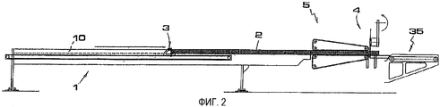
- на фиг.2 показано устройство по фиг.1 с колодой, захваченной зажимными средствами и подвергаемой операции резки;- figure 2 shows the device of figure 1 with a deck captured by clamping means and subjected to a cutting operation;
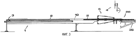
- на фиг.3 показано устройство по фиг.1 с другой колодой, загруженной в соответствующий канал платформы для скольжения колод;- figure 3 shows the device of figure 1 with another deck loaded in the corresponding channel of the platform for sliding decks;
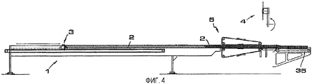
- на фиг.4 показано устройство по фиг.1 с двумя колодами, расположенными в линию одна за другой;- figure 4 shows the device of figure 1 with two decks arranged in a line one after another;
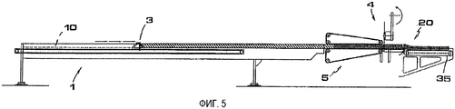
- на фиг.5 показано устройство по фиг.4 со второй колодой, головная часть которой помещена между зажимными средствами;- figure 5 shows the device of figure 4 with a second deck, the head of which is placed between the clamping means;
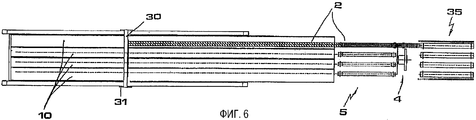
- на фиг.6 показан план устройства по фиг.5;- figure 6 shows a plan of the device of figure 5;
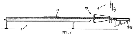
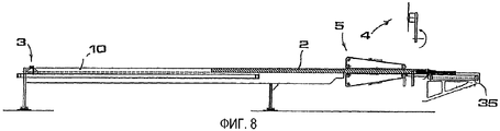
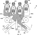
- на фиг.7 и 8 показано то же устройство в ходе двух рабочих операций, которые следуют за операцией, представленной на фиг.6;- in Figs. 7 and 8, the same device is shown during two working operations that follow the operation shown in Fig. 6;
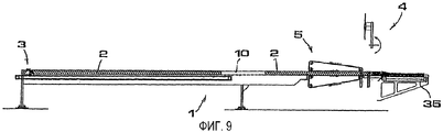
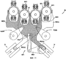
- на фиг.9 показано то же устройство в ходе следующей операции, с другой колодой, загруженной на платформу;- Fig.9 shows the same device during the next operation, with another deck loaded on the platform;
- на фиг.10 и 11 показаны схематические виды спереди конфигураций средств для временного удержания колод различного диаметра на участке резки соответственно;- figure 10 and 11 show schematic front views of configurations of means for temporarily holding decks of various diameters in the cutting area, respectively;
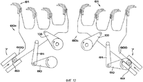
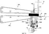
- на фиг.12 показан схематический вид средства удержания по фиг. 10 и 11 с разделением на детали;- FIG. 12 is a schematic view of the holding means of FIG. 10 and 11, divided into parts;
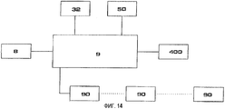
- на фиг.13 показана упрощенная блок-схема автоматического средства привода и контроля.- Fig.13 shows a simplified block diagram of an automatic means of drive and control.
Ограничиваясь этой базовой конструкцией, при ссылке на ссыльные позиции на прилагаемых чертежах, устройство согласно настоящему изобретению содержит:Limited to this basic structure, with reference to the reference position in the accompanying drawings, the device according to the present invention contains:
- платформу (1) с одним или несколькими продольными каналами (10), внутри которых располагаются предназначенные для резки колоды;- a platform (1) with one or more longitudinal channels (10), inside of which there are decks intended for cutting;
- толкательное средство (3), действующее совместно с указанной платформой (1) и предназначенное для воздействия на заднюю сторону колод (2) для того, чтобы толкать их по соответствующим направляющим каналам (10) в направлении режущих средств (4), расположенных далее;- pushing means (3), acting in conjunction with the specified platform (1) and designed to act on the rear side of the decks (2) in order to push them along the respective guide channels (10) in the direction of the cutting means (4) located next;
- зажимное средство (5), расположенное между указанным толкательным средством (3) и указанным режущим средством (4) и предназначенное для захвата колод (2), которые проталкиваются по каналам (10) платформы (1) толкателями, и продвижения их вплоть до указанного режущего средства (4).- clamping means (5) located between the indicated pusher means (3) and the specified cutting means (4) and designed to capture decks (2), which are pushed along the channels (10) of the platform (1) with pushers, and advance them up to the specified cutting means (4).
Преимущественно указанное толкательное средство (3) содержит штангу (30), расположенную поперек каналов (10) платформы (1) и перемещаемую к указанным зажимным средствам (5) и от них кареткой (31), связанной с соответствующим электродвигателем (32) (показанным только на блок-схеме на фиг.14), и установленную для скольжения по двум длинным сторонам платформы (1).Advantageously, said pushing means (3) comprises a rod (30) located across the channels (10) of the platform (1) and moved to and from said clamping means (5) by a carriage (31) connected to the corresponding electric motor (32) (shown only on the block diagram in Fig. 14), and installed for sliding along the two long sides of the platform (1).
Кроме того, преимущественно указанные зажимные средства (5) выполнены из двух замкнутых ремней (50) с приводом от двигателя, расположенных друг напротив друга относительно плоскости (2), по которой поступают колоды (2), скользящие по платформе, так что каждый ремень будет всегда обладать отрезком (51), параллельным такой плоскости, при этом обращенные друг к другу отрезки (51) указанных ремней (50) отделяются друг от друга расстоянием, по существу равным наружному диаметру колод (2).In addition, mainly said clamping means (5) are made of two closed belts (50) driven by an engine located opposite each other relative to the plane (2) along which the decks (2) are received, sliding on the platform, so that each belt will always have a segment (51) parallel to such a plane, while the segments (51) of said belts (50) facing each other are separated from each other by a distance substantially equal to the outer diameter of the decks (2).
Например, как показано на прилагаемых чертежах, указанное режущее средство (4) содержит полотно (40), установленное на несущем рычаге (41), который связан с соответствующим исполнительным механизмом (400) (см. блок-схему на фиг.14) для его перемещения к предназначенным для резки колодам (2) и от них.For example, as shown in the accompanying drawings, said cutting means (4) comprises a blade (40) mounted on a support arm (41) that is connected to a corresponding actuator (400) (see the block diagram of FIG. 14) for moving to and from cutting decks (2).
Работа описанного выше устройства происходит следующим образом.The operation of the above device is as follows.
Колоды (2) размещаются в каналах (10) платформы (1) автоматическими загрузочными устройствами (которые известны специалистам в данной области техники и поэтому не описываются здесь в деталях), а толкательное средство (3) применяется для проталкивания их в направлении ремней (50) вплоть до участка между параллельными отрезками (51) последних (фиг.1 и 2). В этой точке каждая колода (2), установленная таким образом, оказывается зажатой между этими ремнями (50), которые за счет вращения соответствующих тянущих роликов направляют колоду к режущему средству (4), как показано на фиг.3, и удерживают эту колоду с ее диаметрально противоположных поверхностных участков. Перемещение ремней (50) и соответственно колод (2) является прерывистым и синхронным с режущим средством (4): при каждой остановке средство (4) действует так, что происходит резка колод (2), в то время как при движении ремней (50) средство не работает и отведено от колод (2). Скорость и длительность работы ремней (50) устанавливаются заранее в зависимости от длины рулонов бумаги (20), которая должна быть получена при резке колод (2). После того, как колоды (2) оказываются зажаты между ремнями (50), каретка (31) перемещается назад, чтобы принять соответствующее исходное положение, так что при поступлении следующих колод (2) в каналы платформы (1) эти колоды могут перемещаться вновь тем же толкательным средством, вплоть до достижения контакта их соответствующих головных частей с хвостовыми участками колод (2), предварительно переданных к ремням (50), как показано на фиг.4. Этот процесс повторяется циклично, как показано также на фиг.5-9. Из указанного следует, что подача колод (2) к режущему средству происходит непрерывно, т.е. без перерывов или свободных участков между последовательно идущими колодами, что дает очевидные преимущества в отношении фактической производительности системы. Рулоны по мере их производства (20) проталкиваются теми же подвергаемыми обработке колодами (2) на расположенную после режущего средства (4) конвейерную ленту (35), которая обеспечивает их удаление. Между конвейерной лентой (35) и режущим средством (4) может находиться стационарная плоскость (350).The decks (2) are placed in the channels (10) of the platform (1) by automatic loading devices (which are known to specialists in this field of technology and therefore are not described in detail here), and the pushing means (3) is used to push them in the direction of the belts (50) up to the section between parallel segments (51) of the latter (Figs. 1 and 2). At this point, each deck (2), thus installed, is sandwiched between these belts (50), which, by rotating the corresponding pulling rollers, direct the deck to the cutting means (4), as shown in Fig. 3, and hold this deck with its diametrically opposite surface areas. The movement of the belts (50) and accordingly the decks (2) is intermittent and synchronous with the cutting means (4): at each stop, the means (4) acts so that the decks (2) are cut, while when the belts (50) move the product does not work and is diverted from the decks (2). The speed and duration of the belts (50) are set in advance depending on the length of the paper rolls (20), which should be obtained when cutting decks (2). After the decks (2) are sandwiched between the belts (50), the carriage (31) moves back to take the appropriate initial position, so that when the next decks (2) enter the channels of the platform (1), these decks can again move the same pusher, until the contact of their respective head parts with the tail sections of the decks (2) previously transferred to the belts (50), as shown in Fig.4. This process is repeated cyclically, as also shown in FIGS. 5-9. From the above it follows that the supply of decks (2) to the cutting means occurs continuously, i.e. without interruptions or free spaces between consecutive decks, which gives obvious advantages in relation to the actual system performance. The rolls as they are produced (20) are pushed by the same decks being processed (2) onto the conveyor belt (35) located after the cutting means (4), which ensures their removal. Between the conveyor belt (35) and the cutting means (4) there may be a stationary plane (350).
Производственный способ, являющийся предметом настоящего изобретения, включает в себя, таким образом, операцию продольного перемещения предназначенных к резке колод (2) с проталкиванием и последующую операцию продольного перемещения тех же колод (2) с протягиванием.The manufacturing method that is the subject of the present invention, therefore, includes the operation of longitudinal movement intended for cutting decks (2) with pushing and the subsequent operation of longitudinal movement of the same decks (2) with pulling.
Рассматриваемый способ может осуществляться, например, с помощью описанного выше устройства и позволяет добиться непрерывной подачи колод (2) за счет сочетания указанных операций проталкивания и протягивания колод (2).The considered method can be carried out, for example, using the device described above and allows to achieve a continuous supply of decks (2) by combining the indicated operations of pushing and pulling decks (2).
При загрузке на платформу (1) выровненных колод можно также добиться более однородного качества реза всех рулонов от первого до последнего, полученных из каждой колоды. Можно также двигать ремни (50) таким образом, чтобы удвоить последний шаг при прохождении хвостовой части колоды и головной части следующей колоды, согласуя его с работой режущего средства (4). В этом случае выравнивание колод не предусматривается (в то время как, наоборот, обычно это предусматривается для невыровненных колод). Использование выровненных колод способствует дальнейшему повышению производительности.When loading aligned decks onto the platform (1), it is also possible to achieve a more uniform cut quality for all rolls from the first to the last, obtained from each deck. You can also move the belts (50) in such a way as to double the last step when passing the tail of the deck and the head of the next deck, matching it with the work of the cutting means (4). In this case, alignment of decks is not provided (while, on the contrary, it is usually provided for unaligned decks). Using aligned decks further enhances productivity.
Преимущественно в сочетании с режущими средствами (4) может быть предусмотрено дополнительное средство (6) для временного удерживания колод (2) во время операции резки, т.е. в то время, когда режущие средства приведены в действие.Advantageously, in combination with cutting means (4), additional means (6) can be provided for temporarily holding the decks (2) during the cutting operation, i.e. at the time when the cutting means are actuated.
Указанное удерживающее средство (6) согласно типовому варианту реализации, показанному на фигурах прилагаемых чертежей, содержит две пластины (60а, 60b), каждая из которых имеет, с одной стороны, несколько жестких, по существу полукруглых крюков, которые далее именуются «лапами», а с противоположной стороны - выступ (600), установленный с возможностью скольжения в пазу (7), наклоненном под определенным углом относительно вертикали: указанные пластины (60а, 60b) связаны с исполнительным механизмом (8), приводящим их под управлением по существу в прямолинейное движение по соответствующим направляющим (7), причем эти пластины располагаются в параллельном и зеркальном относительно друг друга положении, т.е. ортогонально относительно предназначенных для обработки колод (2).The specified holding means (6) according to the typical embodiment shown in the figures of the accompanying drawings, contains two plates (60a, 60b), each of which has, on the one hand, several rigid, essentially semicircular hooks, which are hereinafter referred to as “paws”, and on the opposite side, a protrusion (600) that slides in a groove (7), inclined at a certain angle relative to the vertical: these plates (60a, 60b) are connected to the actuator (8), bringing them under control essentially straight frost movement along the respective guides (7), and these plates are located in a parallel and mirror position relative to each other, i.e. orthogonal to the decks intended for processing (2).
Выступы (600) указанных пластин (60а, 60b) снабжены небольшими роликами (63), способствующими их скольжению в соответствующих направляющих (7).The protrusions (600) of said plates (60a, 60b) are provided with small rollers (63), which facilitate their sliding in the respective guides (7).
Предпочтительно указанная направляющая (7) наклонена относительно вертикали под углом от 60° до 65°, чтобы обеспечить то, что считается оптимальным сочетанием вертикальных и горизонтальных составляющих смещения каждой лапы (61) и позволить устройству работать как можно лучше вне зависимости от диаметра колоды, подвергаемой обработке, что делает его чрезвычайно гибким в работе.Preferably, said guide (7) is inclined relative to the vertical at an angle of 60 ° to 65 ° to ensure what is considered the optimal combination of vertical and horizontal components of the displacement of each leg (61) and to allow the device to work as best as possible, regardless of the diameter of the deck being processing, which makes it extremely flexible in operation.
Например, указанный исполнительный механизм (8) может быть электрическим двигателем, соединенным с двумя пластинами (60а, 60b) передаточным устройством с кривошипом и соединительной тягой (80, 81), воздействующим на оси поворота (83), пропущенные через две пластины (60а, 60b); указанные пластины (60а, 60b) взаимодействуют с неподвижным корпусом (100) через соответствующие рычаги (108), каждый из которых, с одной стороны, шарнирно соединен с одним из двух неподвижных корпусов (100) и, с другой стороны, шарнирно соединен с одной из двух пластин (60а, 60b) над указанными осями поворота (83). Оси шарниров, соединяющих рычаги (108) с пластинами (60а, 60b), параллельны осям поворота (83).For example, the specified actuator (8) can be an electric motor connected to two plates (60a, 60b) with a crank gear and connecting rod (80, 81) acting on the pivot axes (83), passed through two plates (60a, 60b); these plates (60a, 60b) interact with the stationary body (100) through the corresponding levers (108), each of which, on the one hand, is pivotally connected to one of the two stationary bodies (100) and, on the other hand, is pivotally connected to one of two plates (60a, 60b) above the indicated rotation axes (83). The axis of the hinges connecting the levers (108) with the plates (60a, 60b) are parallel to the rotation axes (83).
Когда режущие средства (4) не работают и отведены от колод (2), пластины (60а, 60b) подняты (как показано пунктиром на фиг.12), так что колоды (2) могут свободно перемещаться вперед (под воздействием тягового усилия, которое прикладывают к ним указанные ремни (50). Непосредственно перед началом шага резки колод (2), т.е. когда колоды оказываются в положении резки, пластины (60а, 60b) опускаются (см. фиг.10 и 11 и изображение со сплошными линиями на фиг. 12), сжимая поверхность колод с помощью крюков (61), которые, будучи приблизительно полукруглыми и зеркально расположенными, охватывают колоды сбоку, а также сверху, удерживая их таким образом в заданном положении. Нижней своей стороной колоды (2) лежат на соответствующих ремнях (50) и частично на плоскости (350). Опускание и подъем пластин (60а, 60b) осуществляются исполнительным механизмом (8) с помощью упомянутой выше совокупности рычагов.When the cutting means (4) are not working and retracted from the decks (2), the plates (60a, 60b) are raised (as shown by the dotted line in FIG. 12), so that the decks (2) can freely move forward (under the influence of traction, which these belts (50) are applied to them. Immediately before the start of the cutting step of the decks (2), i.e. when the decks are in the cutting position, the plates (60a, 60b) are lowered (see Figs. 10 and 11 and the image with solid lines in Fig. 12), compressing the surface of the decks with hooks (61), which, being approximately semicircular and mirror-split married, they cover the decks from the side, as well as from above, holding them in this way in a predetermined position.The lower side of the deck (2) lies on the respective belts (50) and partially on the plane (350) .The lowering and raising of the plates (60a, 60b) are carried out an actuator (8) using the aforementioned set of levers.
Управление толкательным средством (3), зажимным средством (5), режущими средствами (4) и исполнительным механизмом (8), причем последний осуществляет перенос пластин (60а, 60b) полностью автоматизировано с использованием соответствующих программируемых электронных средств, с которыми соединены также оптические средства управления (90) от фотоэлементов, причем последние расположены вдоль технологической линии обработки колод (2) на известных и заранее установленных пунктах. Такие электронные средства известны специалистам в области промышленной автоматики и поэтому не будут описаны более подробно.The control of the pushing means (3), the clamping means (5), the cutting means (4) and the actuator (8), the latter carrying out the transfer of the plates (60a, 60b) is fully automated using appropriate programmable electronic means, to which optical means are also connected control (90) from the photocells, the latter being located along the processing line for processing decks (2) at known and predetermined points. Such electronic means are known to specialists in the field of industrial automation and therefore will not be described in more detail.
На практике детали конструкции могут варьироваться любым эквивалентным образом в отношении того, что касается формы, размеров, расположения элементов и характера используемых материалов, тем не менее без отступления от объема и принципа изобретения.In practice, the structural details can vary in any equivalent way with regard to the shape, size, arrangement of elements and the nature of the materials used, however, without departing from the scope and principle of the invention.
Claims (9)
Applications Claiming Priority (2)
| Application Number | Priority Date | Filing Date | Title |
|---|---|---|---|
| ITFI2003A000115 | 2003-04-24 | ||
| ITFI20030115 ITFI20030115A1 (en) | 2003-04-24 | 2003-04-24 | DEVICE AND METHOD FOR HANDLING LOGS IN CUTTING MACHINES |
Publications (2)
| Publication Number | Publication Date |
|---|---|
| RU2005136427A RU2005136427A (en) | 2006-06-10 |
| RU2307732C2 true RU2307732C2 (en) | 2007-10-10 |
Family
ID=33307119
Family Applications (1)
| Application Number | Title | Priority Date | Filing Date |
|---|---|---|---|
| RU2005136427A RU2307732C2 (en) | 2003-04-24 | 2004-03-22 | Method for moving logs in cutting-off machine tools and apparatus for performing the same |
Country Status (12)
| Country | Link |
|---|---|
| US (4) | US20060162517A1 (en) |
| EP (1) | EP1615753B1 (en) |
| JP (1) | JP4417376B2 (en) |
| CN (1) | CN100415466C (en) |
| AT (1) | ATE439959T1 (en) |
| BR (1) | BRPI0407634B1 (en) |
| DE (1) | DE602004022648D1 (en) |
| ES (1) | ES2330000T3 (en) |
| IL (1) | IL169924A (en) |
| IT (1) | ITFI20030115A1 (en) |
| RU (1) | RU2307732C2 (en) |
| WO (1) | WO2004094118A1 (en) |
Families Citing this family (12)
| Publication number | Priority date | Publication date | Assignee | Title |
|---|---|---|---|---|
| ITFI20060292A1 (en) * | 2006-11-24 | 2008-05-25 | Futura Spa | CUTTING-OFF MACHINE FOR LOGS OF PAPER MATERIAL. |
| JP5626208B2 (en) | 2009-06-11 | 2014-11-19 | 三菱瓦斯化学株式会社 | Ammoxidation catalyst and method for producing nitrile compound using the same |
| ITPI20120073A1 (en) * | 2012-06-22 | 2013-12-23 | Maflex S R L | PUSHING DEVICE FOR PAPER LOGS IN CUTTING MACHINES |
| DE102014106353A1 (en) | 2014-05-07 | 2015-11-12 | Inauen Group Ag | cutting machine |
| CH710403B1 (en) * | 2014-11-24 | 2019-06-14 | Multivac Haggenmueller Kg | Cuts cutting machine. |
| US11065776B2 (en) | 2016-12-09 | 2021-07-20 | The Procter & Gamble Company | Finished products formed from cutting convolutely wound logs of web materials |
| US20180162006A1 (en) * | 2016-12-09 | 2018-06-14 | The Procter & Gamble Company | Clamping device for machines used for transversally cutting convolutely wound logs of web materials |
| US11584033B2 (en) * | 2016-12-09 | 2023-02-21 | The Procter & Gamble Company | Device for transversally cutting convolutely wound logs of web materials |
| US11117283B2 (en) * | 2016-12-13 | 2021-09-14 | O.M.T. S.R.L. | Machine for cutting to size rolls of predefined length from logs with a greater length |
| CN109877655B (en) * | 2018-02-16 | 2021-05-28 | 南京幸庄科技创新产业园管理有限公司 | Directional conveying cutting and automatic chamfering method for section of rod-shaped building material |
| IT201900002851A1 (en) | 2019-02-27 | 2020-08-27 | Plusline S R L | SYSTEM AND OPERATING METHOD FOR THE PACKAGING OF PAPER ROLLS. |
| IT201900002855A1 (en) | 2019-02-27 | 2020-08-27 | Plusline S R L | SYSTEM AND OPERATING METHOD FOR THE PACKAGING OF PAPER ROLLS. |
Family Cites Families (38)
| Publication number | Priority date | Publication date | Assignee | Title |
|---|---|---|---|---|
| US2664927A (en) * | 1949-05-23 | 1954-01-05 | American Mfg Company Inc | Panel trim apparatus with orienting feed means |
| US2657784A (en) * | 1949-06-02 | 1953-11-03 | Stoker Lyman Paul | Automatic feeder |
| US2811183A (en) * | 1953-06-15 | 1957-10-29 | Int Paper Co | Wood defibering apparatus |
| US2842169A (en) * | 1957-03-15 | 1958-07-08 | Curt G Joa | Automatic feed for squaring work fed to the saw or saws of a tenoner |
| US3144893A (en) * | 1957-09-23 | 1964-08-18 | Emhart Mfg Co | Bacon slicer having automatic feed adjustment |
| US3133574A (en) * | 1957-10-14 | 1964-05-19 | Swift & Co | Control of group size in bacon slicing |
| US3045728A (en) * | 1959-04-07 | 1962-07-24 | Ibis Entpr Ltd | Conveying mechanism |
| US3133850A (en) * | 1960-11-17 | 1964-05-19 | Alenius Nils Robert | Continuous making of plywood |
| US3483780A (en) * | 1967-07-19 | 1969-12-16 | Nypel Inc | Cutter |
| US3783725A (en) * | 1972-04-26 | 1974-01-08 | Forano Ltd | Mechanical shears |
| US3844398A (en) * | 1973-01-15 | 1974-10-29 | G Pinat | Self-centering dual belt conveyor |
| US3880295A (en) * | 1973-11-08 | 1975-04-29 | Thermoplastic Engineering Inc | Vacuum gripper device for slicing machine |
| US4036270A (en) * | 1974-12-05 | 1977-07-19 | Robert L. Westbrook | Log peeling machine |
| US4041813A (en) * | 1976-02-17 | 1977-08-16 | Paper Converting Machine Company | Method and apparatus for transverse cutting |
| SE451554B (en) * | 1982-06-23 | 1987-10-19 | Waco Jonsereds Ab | SET AND PLANT FOR PROCESSING SEPARATE COLLECTION OF LONG-TERM FOREMALS LIKE WOODEN LENGTHS |
| DE3316857A1 (en) * | 1983-05-07 | 1984-11-08 | Kupfermühle Holztechnik GmbH, 6430 Bad Hersfeld | MULTI-SIDED PLANER |
| US4522241A (en) * | 1983-08-05 | 1985-06-11 | Gene West, Inc. | Log splitter |
| GB8605773D0 (en) * | 1986-03-08 | 1986-04-16 | Mechatherm Eng Ltd | Dividing logs of heated metal into billets |
| US4922773A (en) * | 1988-01-05 | 1990-05-08 | Itoh Iron Works Co., Ltd. | Three-side cutting apparatus |
| US4800937A (en) * | 1988-01-14 | 1989-01-31 | Mangus Sr Kenneth H | Log splitting apparatus |
| FR2627891B1 (en) * | 1988-02-29 | 1990-08-17 | Sgn Soc Gen Tech Nouvelle | PUSH BUTTON FOR IRRADIATED COMBUSTIBLE ELEMENTS STORE |
| US5109740A (en) * | 1990-11-21 | 1992-05-05 | Belco Industries, Inc. | Billet cut-off control |
| IT1247330B (en) * | 1991-04-03 | 1994-12-12 | Perini Fabio Spa | CUTTING MACHINE FOR CUTTING ROLLS OF TAPE MATERIAL. |
| US5373878A (en) * | 1993-09-02 | 1994-12-20 | Cm Machinery Corporation | Log conveyor for a scragg mill |
| US6089135A (en) * | 1994-09-20 | 2000-07-18 | Murray; Robert J. | Method and apparatus for bucksawing logs |
| CA2131056C (en) * | 1994-08-29 | 2000-07-18 | Robert James Murray | Method and apparatus for bucksawing logs |
| US5544557A (en) * | 1995-01-13 | 1996-08-13 | Paper Converting Machine Company | Method and apparatus for cutting superposed webs |
| WO1996039040A1 (en) * | 1995-06-05 | 1996-12-12 | The Pillsbury Company | An indexer for moving food along a processing line in a precise manner |
| GB2328398A (en) * | 1997-08-19 | 1999-02-24 | Jali Ltd | Cutting Machine. |
| US6042864A (en) * | 1998-06-19 | 2000-03-28 | United Bakery Equipment Co. | Method and apparatus for cutting bread bowl bakery products |
| MXPA02005573A (en) * | 1999-12-03 | 2004-09-10 | Bretting C G Mfg Co Inc | Log saw clamp apparatus and method. |
| IT1317794B1 (en) * | 2000-06-01 | 2003-07-15 | Giovanni Gambini | CUTTING HEAD OF MULTIPLE ROLLS OF DRY AND / OR HYGIENIC PAPER |
| US6532851B2 (en) * | 2000-12-21 | 2003-03-18 | Paper Converting Machine Company | Apparatus for supporting product during cutting |
| EP1238763A1 (en) * | 2001-03-09 | 2002-09-11 | N.V. Techno-Food | Method and apparatus for slicing a number of articles, in particular tomatoes into a plurality of uniform thin slices in a single operation |
| CA2377198A1 (en) * | 2001-03-23 | 2002-09-23 | Kraft Foods Holdings, Inc. | Automated system and method for placing sliced food stacks in packages |
| US7213493B2 (en) * | 2001-10-26 | 2007-05-08 | Goss International Americas, Inc. | Infeed apparatus for a sheet material article trimmer |
| US6763748B2 (en) * | 2002-07-26 | 2004-07-20 | Formax, Inc. | Automatic draft length compensation for slicing machine system |
| US6935215B2 (en) * | 2002-08-14 | 2005-08-30 | Formax, Inc. | Slicing machine and conveyor system with automatic product width compensation |
-
2003
- 2003-04-24 IT ITFI20030115 patent/ITFI20030115A1/en unknown
-
2004
- 2004-03-22 AT AT04722379T patent/ATE439959T1/en not_active IP Right Cessation
- 2004-03-22 US US10/547,435 patent/US20060162517A1/en not_active Abandoned
- 2004-03-22 CN CNB2004800064258A patent/CN100415466C/en not_active Expired - Fee Related
- 2004-03-22 BR BRPI0407634-6A patent/BRPI0407634B1/en not_active IP Right Cessation
- 2004-03-22 ES ES04722379T patent/ES2330000T3/en not_active Expired - Lifetime
- 2004-03-22 RU RU2005136427A patent/RU2307732C2/en active
- 2004-03-22 WO PCT/IT2004/000139 patent/WO2004094118A1/en active Application Filing
- 2004-03-22 DE DE200460022648 patent/DE602004022648D1/en not_active Expired - Lifetime
- 2004-03-22 EP EP04722379A patent/EP1615753B1/en not_active Expired - Lifetime
- 2004-03-22 JP JP2006507641A patent/JP4417376B2/en not_active Expired - Lifetime
-
2005
- 2005-07-27 IL IL16992405A patent/IL169924A/en not_active IP Right Cessation
-
2008
- 2008-03-25 US US12/054,670 patent/US20080163732A1/en not_active Abandoned
-
2012
- 2012-05-08 US US13/466,494 patent/US10682781B2/en not_active Expired - Lifetime
-
2013
- 2013-12-23 US US14/138,579 patent/US10695931B2/en not_active Expired - Lifetime
Also Published As
| Publication number | Publication date |
|---|---|
| EP1615753A1 (en) | 2006-01-18 |
| US20080163732A1 (en) | 2008-07-10 |
| RU2005136427A (en) | 2006-06-10 |
| US10682781B2 (en) | 2020-06-16 |
| JP2006524141A (en) | 2006-10-26 |
| BRPI0407634B1 (en) | 2022-09-20 |
| ITFI20030115A1 (en) | 2004-10-25 |
| CN1777493A (en) | 2006-05-24 |
| US20140102272A1 (en) | 2014-04-17 |
| BRPI0407634A (en) | 2006-02-21 |
| ATE439959T1 (en) | 2009-09-15 |
| US20120216661A1 (en) | 2012-08-30 |
| CN100415466C (en) | 2008-09-03 |
| IL169924A (en) | 2009-09-01 |
| ES2330000T3 (en) | 2009-12-03 |
| EP1615753B1 (en) | 2009-08-19 |
| US20060162517A1 (en) | 2006-07-27 |
| US10695931B2 (en) | 2020-06-30 |
| WO2004094118A1 (en) | 2004-11-04 |
| JP4417376B2 (en) | 2010-02-17 |
| DE602004022648D1 (en) | 2009-10-01 |
Similar Documents
| Publication | Publication Date | Title |
|---|---|---|
| RU2307732C2 (en) | Method for moving logs in cutting-off machine tools and apparatus for performing the same | |
| US7325764B2 (en) | Method and apparatus for winding field coils for dynamo-electric machines | |
| US20140113791A1 (en) | Apparatus for trimming paper rolls or logs and an operating method for treating the logs | |
| IL170122A (en) | Apparatus for temporarily holding logs within cutting-off machines | |
| JP2008221426A (en) | Cutting method and device for rice cake | |
| US20030167887A1 (en) | Product separation apparatus and method | |
| CN115365574A (en) | Double-station pipe cutting machine | |
| JP3948780B2 (en) | Waste material processing method and waste material processing apparatus for long material cutting device | |
| GB1334563A (en) | Apparatus and method for covering cylindrical articles | |
| EP1506068A1 (en) | Log saw apparatus and method | |
| JPH1043931A (en) | Scrap borer and method for winding scrap | |
| EP3838854A1 (en) | Method for cutting a glass sheet | |
| SU1666351A1 (en) | Device for laying cord layers on assembling drum | |
| CN117381900A (en) | Cutting device | |
| JPH06329307A (en) | Core cutting device | |
| JPH08108314A (en) | Material feeding method in angle setting-and cutting machine and device thereof | |
| JPH0250831B2 (en) | ||
| JP2000024893A (en) | Round steel product end face deburring device |