RU2298103C1 - Loading-transporting machine - Google Patents
Loading-transporting machine Download PDFInfo
- Publication number
- RU2298103C1 RU2298103C1 RU2005135807/03A RU2005135807A RU2298103C1 RU 2298103 C1 RU2298103 C1 RU 2298103C1 RU 2005135807/03 A RU2005135807/03 A RU 2005135807/03A RU 2005135807 A RU2005135807 A RU 2005135807A RU 2298103 C1 RU2298103 C1 RU 2298103C1
- Authority
- RU
- Russia
- Prior art keywords
- bucket
- loading
- front wall
- teeth
- impact
- Prior art date
Links
Images
Landscapes
- Shovels (AREA)
Abstract
Description
Техническое решение относится к горному делу, а именно к большегрузным (грузоподъемностью более 40 т) погрузочно-транспортным машинам для подземных и открытых горных работ.The technical solution relates to mining, namely to heavy-duty (with a carrying capacity of more than 40 tons) material handling machines for underground and opencast mining.
Известна погрузочно-транспортная машина такого класса (см. Тихонов Н.В., Рысев Г.С. Шахтные погрузочно-транспортные машины. - М.: Недра, 1976, стр.122), которая состоит из силовой установки, ходовой части на пневмошинных колесах, погрузочного органа, состоящего из ковша, стрелы и гидропривода управления. Передняя часть шасси занята погрузочным органом, сзади установлены дизельный привод с нейтрализатором выхлопных газов. Ковши этих мощных машин, оснащенные статическими зубьями, в процессе погрузки крупнокусковой горной массы испытывают значительные сопротивления, препятствующие внедрению ковша в штабель. Решение этой проблемы путем увеличения мощности и соответственно массы машины приводит к повышению энергозатрат на погрузку горной породы и снижению удельных показателей машины.A loading and transport machine of this class is known (see Tikhonov N.V., Rysev G.S. Mine silo loading and transport machines. - M .: Nedra, 1976, p. 122), which consists of a power plant, a pneumatic tire undercarriage wheels, loading organ, consisting of a bucket, boom and hydraulic control. The front of the chassis is occupied by a loading unit, and a diesel drive with an exhaust gas neutralizer is installed at the rear. The buckets of these powerful machines, equipped with static teeth, experience significant resistance during the loading of lumpy rock mass, which impede the introduction of the bucket into the stack. The solution to this problem by increasing the power and, accordingly, the mass of the machine leads to an increase in energy consumption for loading rock and a decrease in the specific performance of the machine.
Наиболее близкой к предлагаемому техническому решению по технической сущности и совокупности существенных признаков является погрузочно-транспортная машина (см. патент Франции №2323825, Е 02 F 5/30, 3/36, приоритет от 9.09.1975), которая состоит из силовой установки, ходовой части, погрузочного ковша, передняя стенка которого с целью уменьшения сопротивления внедрению рабочего органа в трудноразрушаемый, в том числе и крупнокусковый материал, оснащена ударными зубьями, расположенными по всей рабочей кромке, имеющей прямолинейную форму. В качестве источников ударных импульсов служат пневматические или гидравлические ударные устройства, смонтированные на передней стенке ковша и функционирующие независимо друг от друга. Задняя стенка ковша расположена под углом к передней стенке, близким к прямому. Согласно данному изобретению ковш производит одновременно дробление и погрузку скальной породы за короткий промежуток времени одной и той же машиной.Closest to the proposed technical solution for the technical nature and the totality of the essential features is a loading and transport machine (see French patent No. 2323225, E 02 F 5/30, 3/36, priority from 09.09.1975), which consists of a power plant, chassis, loading bucket, the front wall of which is in order to reduce resistance to the introduction of the working body into hard-to-break, including lumpy material, equipped with impact teeth located along the entire working edge, having a straight shape. As sources of shock pulses are pneumatic or hydraulic shock devices mounted on the front wall of the bucket and functioning independently of each other. The rear wall of the bucket is located at an angle to the front wall, close to straight. According to this invention, the bucket simultaneously crushes and loads the rock in a short period of time with the same machine.
К недостаткам известной конструкции следует отнести следующее. Процесс черпания горной породы ковшом погрузочной машины включает: внедрение ковша в штабель горной породы на максимально возможную глубину и наполнение его поворотом стрелы погрузочной машины. Поэтому эффективность наполнения ковша, а следовательно, и полнота использования его полезной вместимости во многом зависят от глубины внедрения ковша в штабель.The disadvantages of the known design include the following. The process of scooping rock with the loader bucket includes: introducing the bucket into the rock pile to the maximum possible depth and filling it with the turn of the loader boom. Therefore, the efficiency of filling the bucket, and therefore the completeness of using its useful capacity, largely depends on the depth of introduction of the bucket into the stack.
Расположение задней стенки ковша известной погрузочной машины под углом к передней стенке, близким к прямому, позволяет более или менее свободно заглублять ковш только на длину передней стенки, дальнейшее внедрение связано с резким повышением сопротивления, вызванным процессом прессования горной породы задней стенкой ковша. Ковш с прямолинейной формой рабочей кромки, как показывает практика, испытывает большое сопротивление при внедрении в штабель горной породы.The location of the back wall of the bucket of the known loading machine at an angle to the front wall close to a straight line allows the bucket to be more or less freely buried only by the length of the front wall, further implementation is associated with a sharp increase in resistance caused by the process of pressing the rock with the back wall of the bucket. A bucket with a rectilinear shape of the working edge, as practice shows, experiences great resistance when introduced into a pile of rock.
Ударные зубья в ковше этой машины расположены по всей его рабочей кромке. Чем больше ширина ковшей погрузочных машин, а она у большегрузных машин достигает 4÷5 м, тем большее число зубьев у рабочей кромки и ударных устройств на передней стенке ковша необходимо установить, а следовательно, требуются дополнительные мощности на их привод. Это ведет к увеличению габаритов и массы машины, при этом снижается удельная ее масса - отношение количества массы горной породы в ковше к массе машины - показатель, характеризующий совершенство конструкции погрузочно-транспортной машины.Impact teeth in the bucket of this machine are located along its entire working edge. The greater the width of the buckets of the loading machines, and it reaches 4 ÷ 5 m in heavy vehicles, the greater the number of teeth at the working edge and impact devices on the front wall of the bucket must be installed, and therefore, additional power is required to drive them. This leads to an increase in the dimensions and mass of the machine, while its specific mass decreases - the ratio of the amount of rock mass in the bucket to the mass of the machine is an indicator that characterizes the perfection of the design of the loading and transport machine.
Таким образом, конструктивные особенности ковша известной погрузочной машины: прямолинейная форма рабочей кромки ковша и задняя стенка, расположенная к передней стенке под углом, близким к прямому, вызывающая дополнительные силы сопротивления внедрению ковша, а также нерациональное расположение ударных зубьев по рабочей кромке передней стенки снижают эффективность работы погрузочно-транспортной машины.Thus, the structural features of the bucket of the famous loading machine: the rectilinear shape of the working edge of the bucket and the rear wall located at an angle close to the front wall, causing additional forces of resistance to the introduction of the bucket, as well as irrational arrangement of the impact teeth on the working edge of the front wall reduce the efficiency work of a loading and transport machine.
Техническая задача - повышение эффективности работы погрузочно-транспортной машины за счет снижения сопротивления внедрению ковша в штабель горной породы и, как следствие этого, увеличения глубины внедрения и улучшения использования полезной вместимости ковша.The technical task is to increase the efficiency of the loading and transporting machine by reducing the resistance to the introduction of the bucket into the rock pile and, as a result, increasing the depth of introduction and improving the use of the useful capacity of the bucket.
Поставленная задача решается тем, что в погрузочно-транспортной машине, включающей погрузочный орган, состоящий из ковша с ударными зубьями, стрелы и гидроцилиндров управления, ходовой механизм и силовую установку, согласно техническому решению передняя стенка ковша выполнена с выступающей за боковые его стенки частью в форме равнобедренного треугольника или близкой к нему формы на расстояние не менее 1/3 общей ее длины, причем рабочую кромку передней стенки ковша образуют равные стороны треугольника, ударные зубья установлены по оси передней стенки, у боковых стенок и с шагом 3÷5 ширины ударного зуба, при этом задняя стенка ковша выполнена с наклоном относительно передней стенки под углом более 90°.The problem is solved in that in a loading and transport machine, including a loading body, consisting of a bucket with impact teeth, a boom and control hydraulic cylinders, a running gear and a power plant, according to the technical solution, the front wall of the bucket is made with a part protruding beyond its side walls in the form an isosceles triangle or a shape close to it at a distance of at least 1/3 of its total length, moreover, the working edge of the front wall of the bucket is formed by equal sides of the triangle, the impact teeth are installed along the axis the middle wall, at the side walls and with a step of 3 ÷ 5 the width of the impact tooth, while the back wall of the bucket is made with an inclination relative to the front wall at an angle of more than 90 °.
Одним из важных показателей погрузочно-транспортных машин является удельная масса машины - отношение массы горной породы в ковше к общей массе этой машины. Чем больше это отношение, тем эффективнее используется полезная вместимость ковша, тем совершеннее конструкция указанной машины. Такая машина за один цикл достигает максимального наполнения ковша, которое находится в пропорциональной зависимости от глубины внедрения.One of the important indicators of material handling machines is the specific gravity of the machine - the ratio of the mass of rock in the bucket to the total mass of this machine. The larger this ratio, the more efficiently the useful capacity of the bucket is used, the more perfect the design of this machine. Such a machine in one cycle reaches the maximum filling of the bucket, which is proportional to the depth of penetration.
Для увеличения глубины внедрения в предлагаемом техническом решении передняя стенка ковша выполнена с выступающей за боковые его стенки частью в форме равнобедренного треугольника или близкой к нему формы на расстояние не менее 1/3 общей ее длины. Такая форма выступающей части передней стенки ковша позволяет повысить удельное усилие внедрения по ее оси, а также на первом этапе заглубления исключить контакт боковых стенок со штабелем, что способствует снижению лобового сопротивления и увеличению глубины внедрения, а следовательно, улучшению наполнения ковша, то есть более эффективному использованию его вместимости.To increase the penetration depth in the proposed technical solution, the front wall of the bucket is made with a part protruding beyond its side walls in the form of an isosceles triangle or a shape close to it at a distance of at least 1/3 of its total length. This shape of the protruding part of the front wall of the bucket allows you to increase the specific force of introduction along its axis, and also at the first stage of deepening to exclude contact of the side walls with the stack, which helps to reduce drag and increase the depth of penetration, and therefore, improve the filling of the bucket, that is, more efficient use of its capacity.
Установка ударных зубьев по оси передней стенки, у боковых стенок и с шагом 3÷5 ширины ударного зуба, по сравнению с прототипом, позволяет, во-первых, уменьшить число ударных зубьев в ковше, во-вторых, сосредоточить их в частях ковша, испытывающих наибольшие сопротивления при его внедрении, т.е. тем самым более эффективно использовать подводимую к ковшу энергию. Кроме того, ударные зубья, установленные в местах сопряжения передней стенки ковша с боковыми стенками, возбуждая в них колебания, уменьшают силы трения горной породы на боковых стенках, снижают их сопротивление внедрению.The installation of impact teeth along the axis of the front wall, at the side walls and with a step of 3 ÷ 5 width of the impact tooth, in comparison with the prototype, allows, firstly, to reduce the number of impact teeth in the bucket, and secondly, to concentrate them in parts of the bucket experiencing greatest resistance during its implementation, i.e. thereby making more efficient use of the energy supplied to the bucket. In addition, the impact teeth installed at the junctions of the front wall of the bucket with the side walls, causing vibrations in them, reduce the friction forces of the rock on the side walls and reduce their resistance to penetration.
Шаг между ударными зубьями выбирается в зависимости от размеров кусков горной породы в пределах 3÷5 ширины ударного зуба. Такое расположение ударных зубьев на передней стенке ковша снижает установленную мощность их привода, общую массу указанной машины, повышая тем самым такой важный показатель эффективности работы машины как удельная масса машины.The step between the impact teeth is selected depending on the size of the pieces of rock within 3 ÷ 5 of the width of the impact tooth. This arrangement of the impact teeth on the front wall of the bucket reduces the installed power of their drive, the total mass of the specified machine, thereby increasing such an important indicator of machine performance as the specific gravity of the machine.
Расположение задней стенки ковша к передней под углом более 90° снижает, в сравнении с прототипом, сопротивление перемещению горной породы в ковше, способствуют лучшему наполнению последнего, повышая тем самым эффективность использования полезной вместимости ковша.The location of the rear wall of the bucket to the front at an angle of more than 90 ° reduces, in comparison with the prototype, the resistance to movement of rock in the bucket, contribute to a better filling of the latter, thereby increasing the efficiency of using the useful capacity of the bucket.
Таким образом, применение предлагаемого технического решения снижает сопротивление внедрению ковша в штабель горной породы и, как следствие этого, увеличивает глубину внедрения, улучшает использование полезной вместимости ковша, повышает производительность погрузочно-транспортной машины.Thus, the application of the proposed technical solution reduces the resistance to the introduction of the bucket into the rock pile and, as a result, increases the depth of introduction, improves the use of the useful capacity of the bucket, increases the productivity of the loading and transport machine.
Целесообразно на передней стенке ковша погрузочно-транспортной машины между ударными зубьями закрепить статические зубья. В процессе работы ковша ударные зубья, взаимодействуя между собой, создают вокруг себя нарушенную зону, превышающую габариты зуба. Поэтому ударные зубья следует устанавливать на передней стенке ковша, как было отмечено выше, в зависимости от размеров кусков породы с определенным шагом, а между ними закреплять статические зубья, которые хорошо работают в нарушенной ударными зубьями зоне, повышая эффективность работы машины.It is advisable to fix static teeth between the impact teeth on the front wall of the bucket of the material handling machine. During the operation of the bucket, the impact teeth, interacting with each other, create around them a disturbed zone that exceeds the dimensions of the tooth. Therefore, percussion teeth should be installed on the front wall of the bucket, as noted above, depending on the size of the pieces of rock with a certain pitch, and between them to fix static teeth that work well in the area violated by the percussion teeth, increasing the efficiency of the machine.
Целесообразно оснастить заднюю стенку ковша вибратором. Вынужденные колебания, создаваемые вибратором в задней стенке, снижают сопротивление перемещению горной породы в ковше, способствуют улучшению его наполнения.It is advisable to equip the rear wall of the bucket with a vibrator. Forced vibrations created by the vibrator in the rear wall, reduce the resistance to movement of rock in the bucket, contribute to the improvement of its filling.
Целесообразно, чтобы в положении загрузки ковша угол между задней стенкой и горизонтальной плоскостью не превышал угол внутреннего трения горной породы. Это снижает силы трения в процессе перемещения горной породы в ковше, уменьшает усилие внедрения в штабель, улучшает наполнение ковша, повышает эффективность использования его полезной вместимости.It is advisable that in the loading position of the bucket, the angle between the rear wall and the horizontal plane does not exceed the angle of internal friction of the rock. This reduces the friction forces in the process of moving the rock in the bucket, reduces the force of introduction into the stack, improves the filling of the bucket, increases the efficiency of using its useful capacity.
Целесообразно снабдить погрузочно-транспортную машину аккумулятором энергоносителя привода ударных зубьев ковша. Время внедрения ковша за цикл черпания, в течение которого должны непрерывно работать ударные зубья, колеблется в пределах 3÷5 с, что составляет не более 10% от общей продолжительности погрузочно-транспортного цикла указанной машины при длине откатки 100 м. Аккумулятор заполняется энергоносителем - воздухом или жидкостью (в зависимости от типа привода ударных зубьев) во время транспортирования горной породы, когда привод погрузочно-транспортной машины менее загружен. Наличие аккумулятора (воздушных или жидкостных ресиверов) для накопления энергоносителя позволяет применить компрессор или маслостанцию меньшей производительности и соответственно снизить потребляемую мощность не менее чем в 10 раз, что, в свою очередь, снижает общую массу указанной машины.It is advisable to equip the loader with an accumulator energy source for the drive of the shock teeth of the bucket. The bucket introduction time for the scooping cycle, during which the impact teeth must work continuously, ranges from 3 to 5 s, which is no more than 10% of the total duration of the loading and transport cycle of this machine with a haul length of 100 m. The battery is filled with energy - air or liquid (depending on the type of drive of the impact teeth) during rock transportation, when the drive of the material handling machine is less loaded. The presence of a battery (air or liquid receivers) for energy storage allows you to use a compressor or oil station of lower productivity and, accordingly, reduce power consumption by at least 10 times, which, in turn, reduces the total weight of the specified machine.
Целесообразно при этом на выходе указанного аккумулятора установить регулятор параметров энергоносителя привода ударных зубьев, который позволяет обеспечивать стабильную работу этого привода.At the same time, it is advisable to install a regulator of the parameters of the energy source of the drive of the impact teeth, which allows for the stable operation of this drive.
Снижение установленной мощности и повышение удельной массы погрузочно-транспортной машины достигается, с одной стороны, за счет уменьшения количества ударных зубьев, установленных на передней стенке ковша, с другой стороны, за счет использования аккумулятора энергоносителя, снижающих в несколько раз мощность привода ударных зубьев. Уменьшение установленной мощности снижает общую массу предлагаемой машины.A reduction in installed power and an increase in the specific gravity of the transporting machine is achieved, on the one hand, by reducing the number of impact teeth mounted on the front wall of the bucket, and on the other hand, by using an energy storage battery that reduces the drive power of impact teeth several times. A decrease in installed power reduces the total weight of the proposed machine.
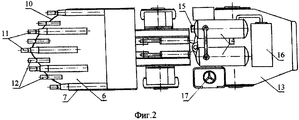
Сущность технического решения поясняется примером конкретного выполнения и чертежами, где на фиг.1 изображена погрузочно-транспортная машина, вид сбоку; на фиг.2 - то же, вид сверху.The essence of the technical solution is illustrated by an example of a specific implementation and drawings, where Fig. 1 shows a material handling machine, side view; figure 2 is the same, a top view.
Погрузочно-транспортная машина (далее - машина) состоит из силовой установки 1 (фиг.1), ходового механизма 2 на пневмошинных колесах 3, погрузочного органа, включающего стрелу 4, гидроцилиндры 5 управления и ковш, состоящий из передней 6 (фиг.2), боковых 7 и задней 8 (фиг.1) с вибратором 9 стенок. Передняя стенка 6 ковша выполнена с выступающей за боковые его стенки 7 частью в форме равнобедренного треугольника или близкой к нему формы на расстояние не менее 1/3 общей ее длины. Задняя стенка 8 наклонена к передней стенке 6 под углом более 90°. Рабочую кромку 10 передней стенки 6 ковша образуют равные стороны треугольника. Ударные зубья 11 установлены по оси передней стенки 6, у боковых стенок 7 и с шагом 3÷5 ширины ударного зуба, между ударными зубьями 11 закреплены статические зубья 12. На раме 13 машины установлен аккумулятор 14 энергоносителя привода ударных зубьев 11 с регулятором 15 параметров энергоносителя и источник 16 энергоносителя (компрессор или маслостанция), место 17 машиниста.The loading and transporting machine (hereinafter referred to as the machine) consists of a power plant 1 (Fig. 1), a running gear 2 on the pneumatic tire wheels 3, a loading member including an arrow 4, control hydraulic cylinders 5 and a bucket consisting of a front 6 (Fig. 2) ,
Работа предлагаемой машины осуществляется следующим образом. Машина подъезжает к штабелю горной породы, ковш с помощью стрелы 4 и гидроцилиндров 5 управления опускается к почве таким образом, чтобы угол между осями зубьев 11, 12 и плоскостью почвы (угол атаки) находился в пределах его оптимального значения 25÷30°, а задняя стенка 8 наклонена к плоскости почвы под углом, не превышающим угол внутреннего трения горной породы. Усилием ходового механизма 2 ковш рабочей кромкой 10 своей передней стенки 6, оснащенной ударными 11 и статическими 12 зубьями, упирается в основание штабеля, под действием реактивных сил ударные зубья 11 включаются в работу, начинается процесс внедрения ковша в штабель и его наполнения горной породой. После наполнения ковша с помощью гидроцилиндров 5 управления стрела 4 поднимает ковш до транспортного положения, включается ходовой механизм 2 и машина следует к месту разгрузки. После разгрузки машина возвращается к штабелю, ковш снова занимает исходное для зачерпывания положение. Далее цикл повторяется.The work of the proposed machine is as follows. The machine drives up to the rock pile, the bucket with the help of the boom 4 and control hydraulic cylinders 5 is lowered to the soil so that the angle between the axes of the
Время внедрения ковша в штабель составляет, как было отмечено выше, не более 3÷5 с. Время транспортирования зависит от скорости передвижения машины и расстояния до места выгрузки, которое колеблется в пределах 50÷300 м. За это время, а оно составляет в среднем до 80÷90% продолжительности всего погрузочно-транспортного цикла, происходит зарядка аккумулятора 14 энергоносителем. Накопленная энергия должна обеспечить непрерывную работу ударных зубьев 11, как минимум, в течение одного внедрения ковша в штабель горной породы.The time of introducing the bucket into the stack is, as noted above, no more than 3–5 s. The transportation time depends on the speed of the machine and the distance to the place of unloading, which varies between 50 ÷ 300 m. During this time, and it averages up to 80 ÷ 90% of the duration of the entire loading and transport cycle, the battery 14 is charged with energy. The accumulated energy must ensure the continuous operation of the
Claims (6)
Priority Applications (1)
| Application Number | Priority Date | Filing Date | Title |
|---|---|---|---|
| RU2005135807/03A RU2298103C1 (en) | 2005-11-17 | 2005-11-17 | Loading-transporting machine |
Applications Claiming Priority (1)
| Application Number | Priority Date | Filing Date | Title |
|---|---|---|---|
| RU2005135807/03A RU2298103C1 (en) | 2005-11-17 | 2005-11-17 | Loading-transporting machine |
Publications (1)
| Publication Number | Publication Date |
|---|---|
| RU2298103C1 true RU2298103C1 (en) | 2007-04-27 |
Family
ID=38106964
Family Applications (1)
| Application Number | Title | Priority Date | Filing Date |
|---|---|---|---|
| RU2005135807/03A RU2298103C1 (en) | 2005-11-17 | 2005-11-17 | Loading-transporting machine |
Country Status (1)
| Country | Link |
|---|---|
| RU (1) | RU2298103C1 (en) |
Cited By (2)
| Publication number | Priority date | Publication date | Assignee | Title |
|---|---|---|---|---|
| RU2344239C1 (en) * | 2007-06-22 | 2009-01-20 | Институт горного дела Сибирского отделения Российской академии наук | Working body of quarry excavator |
| CN101660414B (en) * | 2008-08-29 | 2011-07-20 | 中煤国际工程集团沈阳设计研究院 | Method for conveying coal in end slope laneway in open pit coal mine |
Citations (2)
| Publication number | Priority date | Publication date | Assignee | Title |
|---|---|---|---|---|
| SU1661288A1 (en) * | 1988-06-14 | 1991-07-07 | Специальное конструкторско-технологическое бюро Института геотехнической механики АН УССР | Excavator bucket |
| SU1724817A2 (en) * | 1988-12-19 | 1992-04-07 | А.М.Селезнев, В.М.Усаченко, В.В.Прохоренко, С.Г.Нестеровский, С.М.Калыт к и И.Н.Микитюк | Excavator bucket |
-
2005
- 2005-11-17 RU RU2005135807/03A patent/RU2298103C1/en not_active IP Right Cessation
Patent Citations (2)
| Publication number | Priority date | Publication date | Assignee | Title |
|---|---|---|---|---|
| SU1661288A1 (en) * | 1988-06-14 | 1991-07-07 | Специальное конструкторско-технологическое бюро Института геотехнической механики АН УССР | Excavator bucket |
| SU1724817A2 (en) * | 1988-12-19 | 1992-04-07 | А.М.Селезнев, В.М.Усаченко, В.В.Прохоренко, С.Г.Нестеровский, С.М.Калыт к и И.Н.Микитюк | Excavator bucket |
Cited By (2)
| Publication number | Priority date | Publication date | Assignee | Title |
|---|---|---|---|---|
| RU2344239C1 (en) * | 2007-06-22 | 2009-01-20 | Институт горного дела Сибирского отделения Российской академии наук | Working body of quarry excavator |
| CN101660414B (en) * | 2008-08-29 | 2011-07-20 | 中煤国际工程集团沈阳设计研究院 | Method for conveying coal in end slope laneway in open pit coal mine |
Similar Documents
| Publication | Publication Date | Title |
|---|---|---|
| RU2298103C1 (en) | Loading-transporting machine | |
| CN201753453U (en) | Hydraulic loader-digger | |
| CN203158840U (en) | Movable crushing truck loader | |
| RU189466U1 (en) | BUCKET WORKING ORGAN | |
| CN203393758U (en) | Mining excavating and loading integrated machine | |
| CN201202474Y (en) | Multifunctional full hydraulic chain groove type shoveling rock drill | |
| CN115949397A (en) | A double-drum continuous miner | |
| CN211340902U (en) | Practical coal mine mining loader | |
| CN206015770U (en) | Machine dug by a kind of hook | |
| CN201420274Y (en) | A digging conveyor | |
| CN201140937Y (en) | Bucket type association loading shovel | |
| CN212359775U (en) | Intelligent full-hydraulic drilling, anchoring and protecting four-arm integrated machine for coal mine | |
| WO2002032798A1 (en) | Scoop wheel excavator | |
| RU2729766C1 (en) | Extraction-and-loading machine | |
| CN119711568B (en) | Underground scraper power take-off structure based on dual energy | |
| Levenson et al. | New technology and equipment for non-explosive formation of free face in deep open pit mines | |
| CN223344023U (en) | Bottom breaking roller shovel plate and bottom breaking coal cleaner | |
| CN1583534A (en) | Loader for digging, feeding and loading materials | |
| CN203420708U (en) | Conveying mechanism dedicated to mine mining and loading integrated machine | |
| US20260110155A1 (en) | High Volume Excavating, ripping and Loading Apparatus and Methods | |
| CN200946080Y (en) | Small-sized fork type loading machine | |
| CN215804568U (en) | Multifunctional tunnel undermining machine for coal mine | |
| CN216339749U (en) | Multifunctional engineering excavator | |
| Levenson et al. | Vibratory feeders with elongated conveying surface in rehandling of mined rock in open pit mines | |
| CN200948980Y (en) | Pedrail hydraulic vertical pawl rock mine loader |
Legal Events
| Date | Code | Title | Description |
|---|---|---|---|
| MM4A | The patent is invalid due to non-payment of fees |
Effective date: 20091118 |