RU2297610C2 - Method of sealing branch pipes and bench for testing valving systems - Google Patents
Method of sealing branch pipes and bench for testing valving systems Download PDFInfo
- Publication number
- RU2297610C2 RU2297610C2 RU2005105089/28A RU2005105089A RU2297610C2 RU 2297610 C2 RU2297610 C2 RU 2297610C2 RU 2005105089/28 A RU2005105089/28 A RU 2005105089/28A RU 2005105089 A RU2005105089 A RU 2005105089A RU 2297610 C2 RU2297610 C2 RU 2297610C2
- Authority
- RU
- Russia
- Prior art keywords
- test
- plugs
- pipe
- plug
- sealing
- Prior art date
Links
Images
Abstract
Description
Изобретение относится к испытательной технике для трубопроводной арматуры /ТПА/, в частности шаровых кранов бесфланцевого исполнения.The invention relates to testing equipment for pipe fittings / TPA /, in particular ball valves, wafer version.
Известно устройство для герметизации полых изделий при их испытании на герметичность по а.с. SU 1422041 А1, опубл. 07.09.1998, в котором обеспечена герметизация патрубков бесфланцевого исполнения путем использования гидроцилиндра с упругодеформируемым уплотнительным элементом. Деформация кольцевого уплотнительного элемента обеспечивается его сжатием между выступом полого стержня и втулкой, перемещаемой поршнем гидроцилиндра, в который подается давление от отдельной гидросистемы.A device for sealing hollow products when tested for tightness by AS SU 1422041 A1, publ. 09/07/1998, in which the sealing of nozzles of a flangeless design by using a hydraulic cylinder with an elastically deformable sealing element is provided. The deformation of the annular sealing element is ensured by its compression between the protrusion of the hollow rod and the sleeve, which is moved by the piston of the hydraulic cylinder, into which pressure is supplied from a separate hydraulic system.
Известный способ содержит следующие операции:The known method contains the following operations:
- соосное совмещение и ввод внутрь патрубка выступа стержня гидроцилиндра с уплотнительным кольцом;- coaxial alignment and input into the nozzle of the protrusion of the rod of the hydraulic cylinder with a sealing ring;
- подача избыточного давления в полость гидроцилиндра для обеспечения упругой деформации уплотнительного кольца и поддержание этого давления на все время проведения испытания;- supplying excess pressure to the cavity of the hydraulic cylinder to ensure elastic deformation of the sealing ring and maintaining this pressure for the entire duration of the test;
- подача в полость испытуемого изделия /например, трубопроводной арматуры/ испытательной жидкости под избыточным давлением;- supply to the cavity of the test product / for example, pipe fittings / test fluid under excess pressure;
- контроль параметров испытуемого изделия /например, на стойкость к воздействию испытательной жидкости или негерметичность/;- control of the parameters of the test product / for example, resistance to the effects of the test fluid or leaks /;
- снятие избыточного давления и слив испытательной среды из полости испытуемого изделия;- removing excess pressure and draining the test medium from the cavity of the test product;
- снижение давления в полости гидроцилиндра до атмосферного.- pressure reduction in the cavity of the hydraulic cylinder to atmospheric.
Существенный недостаток этого способа герметизации патрубков бесфланцевого исполнения в необходимости отдельной гидросистемы для создания давления в гидроцилиндре, обеспечивающем деформацию кольцевого уплотнительного элемента. Применительно к ТПА, имеющей два соосно размещенных патрубка, на каждый патрубок потребуется по гидроцилиндру с обеспечением их соосного совмещения без перекосов с патрубками испытуемой ТПА. При диаметрах условного прохода испытуемой ТПА до 800 мм эта операция трудно реализуема.A significant disadvantage of this method of sealing flangeless nozzles in the need for a separate hydraulic system to create pressure in the hydraulic cylinder, which ensures the deformation of the annular sealing element. In relation to a TPA having two coaxially placed nozzles, each nozzle will need a hydraulic cylinder to ensure their coaxial alignment without distortions with the nozzles of the tested TPA. With the diameters of the conditional test TPA up to 800 mm, this operation is difficult to implement.
Техническим результатом изобретения является упрощение способа и стенда для испытания трубопроводной арматуры бесфланцевого исполнения путем использования для герметизации патрубков испытательного давления, создаваемого в полости испытуемой ТПА.The technical result of the invention is to simplify the method and bench for testing pipe fittings of a flangeless design by using the test pressure created in the cavity of the tested injection molding machine to seal the nozzles.
Для достижения технического результата в способе производят поджатие торца второго патрубка ТПА к уплотнительному кольцу второй заглушки, устанавливают ТПА с заглушками через проставочные элементы в стенд, поджимают торцы патрубков к заглушкам через уплотнительные кольца нормированным усилием, достаточным для заполнения внутренней полости ТПА испытательной жидкостью без утечек, после чего осуществляют заполнение внутренней полости ТПА испытательной жидкостью и подают туда испытательное давление, осуществляя при этом сжатие и деформацию уплотнительных колец заглушек и исключая тем самым зазор между внутренней стенкой испытуемой ТПА и уплотнительными кольцами заглушек. В испытательном стенде каждая заглушка содержит корпус с цилиндрической выточкой, в которой размещен поршень с упруго деформируемым кольцами, одно из которых размещено в кольцевом углублении корпуса заглушки и предназначено для поджатия к торцу патрубка испытуемого изделия, второе размещено между торцевыми поверхностями корпуса и поршня заглушки и предназначено для уплотнения зазора между заглушками в внутренней поверхности патрубка, а третий и четвертый размещены между поршнем и цилиндрической выточкой корпуса и служат для ограничения деформации второго кольца заглушки, причем корпус каждой заглушки снабжен штуцером и клапанами для подачи и слива испытательной жидкости через поршень в полость испытуемого изделия, кроме того, одна из заглушек дополнительно снабжена штуцером и каналами для дренажа воздуха через поршень из полости испытуемого изделия в атмосферу и обратно.To achieve a technical result in the method, the end face of the second TPA nozzle is pressed to the sealing ring of the second plug, the TPA with plugs is installed through the spacers in the stand, the ends of the nozzles are pressed to the plugs through the sealing rings with a normalized force sufficient to fill the TPA inner cavity with test fluid without leaks, then fill the inner cavity of the injection molding machine with test liquid and apply test pressure there, while compressing and defo the formation of the sealing rings of the plugs and thereby eliminating the gap between the inner wall of the test TPA and the sealing rings of the plugs. In the test bench, each plug contains a housing with a cylindrical recess, in which a piston with elastically deformable rings is placed, one of which is placed in the annular recess of the plug housing and is designed to press the end of the pipe of the test product, the second is located between the end surfaces of the housing and the piston of the plug to seal the gap between the plugs in the inner surface of the pipe, and the third and fourth are placed between the piston and the cylindrical undercut of the housing and serve to limit deformation of the second ring of the plug, and the housing of each plug is equipped with a fitting and valves for supplying and draining the test fluid through the piston into the cavity of the test product, in addition, one of the plugs is additionally equipped with a fitting and channels for draining air through the piston from the cavity of the tested product into the atmosphere and back.
Кроме того, в устройство введен тройник и соединен со щтуцером для подачи и слива испытательной жидкости одной из заглушек, к первому входу тройника подключен через вентиль источник испытательной жидкости, а ко второму входу тройника подключен через вентиль источник испытательного давления.In addition, a tee is inserted into the device and connected to a fitting for supplying and draining the test fluid of one of the plugs, a source of test fluid is connected to the first input of the tee, and a source of test pressure is connected to the second input of the tee through the valve.
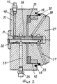
Структура испытательного стенда для ТПА бесфланцевого исполнения приведена на фиг.1. На фиг.2 показан разрез одной из заглушек для герметизации патрубков ТПА бесфланцевого исполнения.The structure of the test bench for TPA wafer version shown in figure 1. Figure 2 shows a section of one of the plugs for sealing nozzles TPA wafer version.
Стенд фиг.1 содержит неподвижную 1 и подвижную 2 планшайбы с присоединительными кольцами 3 и 4, в которые входят выступы проставочных элементов 5 и 6, закрепленных к планшайбам 1 и 2 кронштейнами 7 и 8 соответственно. В углубления 9 и 10 элементов 5 и 6 входят выступы 11 и 12 заглушек 13 и 14 соответственно. Заглушки 13 и 14 присоединены элементами 15 и 16 к патрубкам 17 и 18 испытуемой ТПА и поджаты к торцу патрубков 17 и 18 через упругие уплотнительные кольца 19 и 20 нормированным усилием от планшайбы 2. Заглушка 13 снабжена тройником 21 для подачи и сброса испытуемой жидкости через патрубок 22 и создания испытательного давления в полости испытуемой ТПА через патрубок 23. Кроме того, в верхней части заглушки 13 размещен вентиль со штуцером 24 для дренажа воздуха при заполнении внутренней полости испытуемой ТПА. Правая заглушка 14 оснащена вентилем со штуцером 25 для подачи испытательного давления через патрубок 26 в правую часть испытуемой ТПА, при закрытом состоянии пробки шарового крана, например.The stand of figure 1 contains a fixed 1 and a movable 2 faceplates with connecting rings 3 and 4, which include the protrusions of the spacer elements 5 and 6, fixed to the faceplates 1 and 2 with brackets 7 and 8, respectively. The recesses 9 and 10 of the elements 5 and 6 include the
Процесс испытания состоит из следующих операций:The test process consists of the following operations:
- закрепляют заглушки 13 и 14 к патрубкам 17 и 18 испытуемой ТПА с помощью элементов 15 и 16;- fix the plugs 13 and 14 to the nozzles 17 and 18 of the test TPA using elements 15 and 16;
- устанавливают ТПА с заглушками в стенд через проставочные элементы 5 и 6;- install TPA with plugs in the stand through spacers 5 and 6;
- поджимают нормированным усилием от планшайбы 2 торцы патрубков 17 и 18 к заглушкам 13 и 14 через уплотнительные кольца 19 и 20;- tighten the normalized force from the faceplate 2 to the ends of the nozzles 17 and 18 to the plugs 13 and 14 through the
- заполняют внутреннюю полость испытуемой ТПА испытательной через патрубок 22; после чего вентиль 24 и патрубок 22 перекрывают;- fill the internal cavity of the test TPA test through the pipe 22; after which the valve 24 and the pipe 22 are closed;
- подают испытательное давление через патрубки 23 и 26 в полость ТПА и проводят испытание при различных положениях рабочего органа ТПА /например, пробки шарового крана/.- submit the test pressure through the nozzles 23 and 26 into the cavity of the TPA and conduct the test at various positions of the working body of the TPA / for example, ball plugs /.
По мере роста давления в полости изделия поршни 27 и 28 деформируют уплотнительные кольца 29 и 30 соответственно, чем обеспечена надежная герметизация полости испытуемой ТПА давлением испытательной жидкости без применения отдельной гидросистемы для герметизации и без значительных усилий сжатия корпуса испытываемого изделия.As the pressure in the cavity of the product increases, the
На фиг.2. показан разрез левой заглушки 13 стенда. Поршень 27 может перемещаться в корпусе 31 заглушки под действием давления испытательной жидкости, при этом он деформирует эластичные кольца 32 и 33 и уплотнительное кольцо 29. Испытательное давление подается через штуцер 34 по каналам 35, 36, 37, каналы 38, 39, 40 и штуцер 41 необходимы для дренажа воздуха из полости изделия во время ее заполнения испытательной жидкостью. Кольца 32 и 33 ограничивают деформацию уплотнительного кольца 29 в пределах упругости материала.In figure 2. shows a section of the left stub 13 of the stand. The
Для слива испытательной жидкости из полости испытуемой ТПА перекрывают патрубки 23 и 26, затем открывают сток в патрубках 22, после чего открывают вентиль 24 для доступа воздуха в полость изделия.To drain the test fluid from the cavity of the test TPA, the nozzles 23 and 26 are closed, then the drain in the nozzles 22 is opened, and then the valve 24 is opened for air to enter the cavity of the product.
Новым в предлагаемом способе герметизации патрубков является использование давления испытательной жидкости для самогерметизации внутренней полости испытуемой ТПА. Как следствие, существенно упрощен как процесс герметизации, так и испытательный стенд для ТПА. При этом исключено большое усилие сжатия корпуса испытуемой ТПА.New in the proposed method of sealing the nozzles is the use of pressure of the test fluid for self-sealing of the internal cavity of the tested TPA. As a result, both the sealing process and the test bench for injection molding machines are greatly simplified. In this case, a large compression force of the body of the tested TPA is excluded.
Claims (3)
Priority Applications (1)
| Application Number | Priority Date | Filing Date | Title |
|---|---|---|---|
| RU2005105089/28A RU2297610C2 (en) | 2005-02-24 | 2005-02-24 | Method of sealing branch pipes and bench for testing valving systems |
Applications Claiming Priority (1)
| Application Number | Priority Date | Filing Date | Title |
|---|---|---|---|
| RU2005105089/28A RU2297610C2 (en) | 2005-02-24 | 2005-02-24 | Method of sealing branch pipes and bench for testing valving systems |
Publications (2)
| Publication Number | Publication Date |
|---|---|
| RU2005105089A RU2005105089A (en) | 2006-08-10 |
| RU2297610C2 true RU2297610C2 (en) | 2007-04-20 |
Family
ID=37059055
Family Applications (1)
| Application Number | Title | Priority Date | Filing Date |
|---|---|---|---|
| RU2005105089/28A RU2297610C2 (en) | 2005-02-24 | 2005-02-24 | Method of sealing branch pipes and bench for testing valving systems |
Country Status (1)
| Country | Link |
|---|---|
| RU (1) | RU2297610C2 (en) |
Cited By (5)
| Publication number | Priority date | Publication date | Assignee | Title |
|---|---|---|---|---|
| RU2597672C1 (en) * | 2015-05-27 | 2016-09-20 | Общество с ограниченной ответственностью "Газпром добыча Уренгой" | Test bench for pipeline valves of wafer design |
| RU174493U1 (en) * | 2017-04-26 | 2017-10-17 | Юрий Анатольевич Ануфриев | Device for hydraulic testing of bends |
| RU184191U1 (en) * | 2018-03-06 | 2018-10-18 | Публичное акционерное общество "Татнефть" имени В.Д. Шашина | STAND FOR REPAIR OF OIL AND GAS EQUIPMENT |
| RU2670675C1 (en) * | 2018-01-09 | 2018-10-24 | Общество с ограниченной ответственностью "Научно-производственное объединение "ГАКС-Армсервис" | Tests stand for pipeline fittings, its elements and couplers for strength and trim impermeability |
| RU2722969C1 (en) * | 2019-09-17 | 2020-06-05 | Общество с ограниченной ответственностью "ГАКС-РЕМ-АРМ" | Device for measurement of axial loads acting on pipeline valves during hydraulic tests for strength, density of material and tightness of gate valve |
-
2005
- 2005-02-24 RU RU2005105089/28A patent/RU2297610C2/en not_active IP Right Cessation
Cited By (6)
| Publication number | Priority date | Publication date | Assignee | Title |
|---|---|---|---|---|
| RU2597672C1 (en) * | 2015-05-27 | 2016-09-20 | Общество с ограниченной ответственностью "Газпром добыча Уренгой" | Test bench for pipeline valves of wafer design |
| RU174493U1 (en) * | 2017-04-26 | 2017-10-17 | Юрий Анатольевич Ануфриев | Device for hydraulic testing of bends |
| RU2670675C1 (en) * | 2018-01-09 | 2018-10-24 | Общество с ограниченной ответственностью "Научно-производственное объединение "ГАКС-Армсервис" | Tests stand for pipeline fittings, its elements and couplers for strength and trim impermeability |
| RU2670675C9 (en) * | 2018-01-09 | 2018-12-12 | Общество с ограниченной ответственностью "Научно-производственное объединение "ГАКС-Армсервис" | Tests stand for pipeline fittings, its elements and couplers for strength and trim impermeability |
| RU184191U1 (en) * | 2018-03-06 | 2018-10-18 | Публичное акционерное общество "Татнефть" имени В.Д. Шашина | STAND FOR REPAIR OF OIL AND GAS EQUIPMENT |
| RU2722969C1 (en) * | 2019-09-17 | 2020-06-05 | Общество с ограниченной ответственностью "ГАКС-РЕМ-АРМ" | Device for measurement of axial loads acting on pipeline valves during hydraulic tests for strength, density of material and tightness of gate valve |
Also Published As
| Publication number | Publication date |
|---|---|
| RU2005105089A (en) | 2006-08-10 |
Similar Documents
| Publication | Publication Date | Title |
|---|---|---|
| CN103697284B (en) | A kind of pipe pressure test device | |
| RU2297610C2 (en) | Method of sealing branch pipes and bench for testing valving systems | |
| CN202676556U (en) | Hydrostatic test sealing device | |
| FI80793B (en) | ANORDNING FOER LAECKAGEDETEKTERING. | |
| JP2008045943A (en) | Pressure testing device | |
| CN202852326U (en) | Isolated seal fixture with pressure | |
| RU2364701C1 (en) | Method of preventer crimping on well | |
| CN203628136U (en) | Pipe fitting pressure testing device | |
| CN109630774A (en) | A kind of high intensity nipple | |
| CN105784283A (en) | Gate valve body water pressure testing method and gate valve body water pressure testing tool | |
| JP2020159689A (en) | Watertight testing apparatus | |
| RU2393447C1 (en) | Method of controlling clamping force when testing pipeline fittings | |
| US5515885A (en) | Plug assembly | |
| RU2256824C2 (en) | Stand for testing strength of pipeline valves and fittings | |
| CN108386629A (en) | The method of pipe jointer secondary seal | |
| CN103115191B (en) | Non-glue-injection high-pressure leak point under-pressure plug device | |
| RU2597672C1 (en) | Test bench for pipeline valves of wafer design | |
| CN209945630U (en) | Hydraulic sealing test device | |
| US20070176415A1 (en) | Quick-connect fitting | |
| CN201330905Y (en) | Conveying tube joint | |
| CN208703405U (en) | A kind of fastening of double ring type and injecting combined pipe fixture | |
| CN205938334U (en) | Valve leakage prosthetic devices | |
| CN219914769U (en) | Welding-free water pressure device for floor drain leakage detection | |
| CN219445449U (en) | Ceramic body grouting and high-pressure forming system | |
| RU2297555C2 (en) | Stand for strength testing of pipeline valves |
Legal Events
| Date | Code | Title | Description |
|---|---|---|---|
| MM4A | The patent is invalid due to non-payment of fees |
Effective date: 20080225 |