RU2296373C1 - Device of a set of measuring devices - Google Patents
Device of a set of measuring devices Download PDFInfo
- Publication number
- RU2296373C1 RU2296373C1 RU2005123710/11A RU2005123710A RU2296373C1 RU 2296373 C1 RU2296373 C1 RU 2296373C1 RU 2005123710/11 A RU2005123710/11 A RU 2005123710/11A RU 2005123710 A RU2005123710 A RU 2005123710A RU 2296373 C1 RU2296373 C1 RU 2296373C1
- Authority
- RU
- Russia
- Prior art keywords
- recesses
- length
- recess
- side walls
- cover
- Prior art date
Links
- 238000005192 partition Methods 0.000 claims description 6
- 239000000523 sample Substances 0.000 claims description 5
- 239000000126 substance Substances 0.000 abstract description 4
- 238000004519 manufacturing process Methods 0.000 description 5
- 206010011878 Deafness Diseases 0.000 description 3
- 238000005259 measurement Methods 0.000 description 3
- 230000003993 interaction Effects 0.000 description 2
- 238000013016 damping Methods 0.000 description 1
Images
Landscapes
- Sampling And Sample Adjustment (AREA)
Abstract
Description
Изобретение относится к устройствам комплекта для измерения различных физических и химических параметров при проведении индивидуальных лабораторных работ учащимися общеобразовательных учреждений по таким дисциплинам как физика, химия, биология. Предлагаемое техническое решение может быть использовано и в других областях, например на производстве, где необходимо производить точное и качественное измерение физических и химических параметров.The invention relates to a set of devices for measuring various physical and chemical parameters during individual laboratory work by students of educational institutions in such disciplines as physics, chemistry, biology. The proposed technical solution can be used in other areas, for example, in production, where it is necessary to make an accurate and high-quality measurement of physical and chemical parameters.
Известно техническое решение по патенту РФ №2205457, кл. G 09 В 23/18, 2002 г., в котором корпус включает переднюю, заднюю, скошенные боковые стенки и днище, внутренность которого разделена на секции, снабженные ложементами, для размещения оборудования, а крышка выполнена прозрачной. Однако такое техническое решение корпуса сложно по конструкции и технологически неудобно в изготовлении.Known technical solution according to the patent of the Russian Federation No. 2205457, class. G 09 In 23/18, 2002, in which the case includes a front, rear, beveled side walls and a bottom, the inside of which is divided into sections equipped with lodgements, for accommodating equipment, and the cover is made transparent. However, such a technical solution of the housing is difficult in design and technologically inconvenient to manufacture.
Известно техническое решение по патенту РФ №2205455, кл. G 09 В 23/18, 2002 г., в котором корпус содержит заднюю, боковые, переднюю стенки и днище. Боковые стенки выполнены со скошенным передним углом, а внутренняя поверхность их снабжена пазами. Внутреннее пространство разделено на секции, куда вставлена панель с ложементами для размещения оборудования. Корпус снабжен прозрачной крышкой, вставляемой в пазы боковых сторон и опирается на переднюю стенку. Однако это техническое решение также не технологично в изготовлении и сложно по конструктивному выполнению.Known technical solution according to the patent of the Russian Federation No. 2205455, class. G 09
Наиболее близким техническим решением является решение по патенту РФ №2205456, кл. G 09 В 23/18, 2002 г., в котором корпус содержит заднюю, боковые, переднюю стенки и днище. Боковые стенки выполнены со скошенным передним углом, в результате чего передняя стенка ниже задней. Внутри корпуса выполнены ложементы различной конфигурации для укладки и фиксации приборов и оборудования. Боковые стенки снабжены продольными пазами. Крышка выполнена прозрачной и съемной со скошенной передней частью. Однако такое выполнение устройства не всегда удобно в эксплуатации, не технологично в изготовлении.The closest technical solution is the solution according to the patent of the Russian Federation No. 2205456, class. G 09
Технической задачей настоящего изобретения является создание такого устройство, которое обеспечило бы размещение любого измерительного оборудования для проведения точных замеров параметров в процессе проведения всего комплекса индивидуальных лабораторных работ по изучению дисциплин, включенных в образовательную область «Естествознание» - физика, химия, биология.The technical task of the present invention is the creation of such a device that would ensure the placement of any measuring equipment for accurate measurement of parameters during the entire complex of individual laboratory work on the study of disciplines included in the educational field "Natural Sciences" - physics, chemistry, biology.
Поставленная задача достигается тем что, в устройстве комплекта измерительных приборов, включающего корпус, состоящий из задней стенки, боковых стенок со скошенными передними углами и продольным верхним пазом на их внутренних боковых поверхностях, выполненным параллельно верхним торцам, передней стенки и днища, ложементов для размещения и фиксации приборов, а также съемную прозрачную крышку, корпус снабжен съемной панелью, в которой выполнены разделенные перегородками ложементы, в виде углублений, при этом часть углублений выполнена глухими прямоугольной формы для закрепления амперметров, вольтметра и секундомера, термометра, часть - в виде соединенных двух прямоугольников, различных по ширине и длине, для размещения мультиметра с комплектом соединительных проводов, часть выполнена в виде сквозного углубления для размещения элементов питания, часть - в виде прямоугольника с симметричными ступенчатыми боковыми сторонами для размещения мерного цилиндра с подставкой, при этом углубление первой ступени выполнено сквозным, а остальные ступени углубления - глухими, часть - в виде прямоугольников с закругленными либо одним торцом для размещения динамометра, весов, щупа термометра, либо двумя скругленными торцами для размещения ленты измерительной, а часть углублений - в виде продольного щелевого глухого углубления с боковыми выемками, выполненными по радиусу и разнесенными по длине щели, причем в перегородке, разделяющей углубления для термометра и его щупа, выполнена желобчатая выемка для размещения соединяющего их спиралевидного провода, при этом высота панели выполнена меньшей, чем высота передней стенки корпуса, а передний торец боковых стенок корпуса выполнен высотой большей, чем высота передней стенки корпуса, длина которой выполнена в размер, соответствующий расстоянию между внешними боковыми поверхностями боковых стенок корпуса, а крышка выполнена с двумя перегибами и состоит из горизонтального, наклонного и вертикального участков, при этом свободный торец горизонтального участка крышки входит в паз, выполненный на внутренней поверхности задней стенки корпуса, а длина горизонтального участка равна длине пазов на внутренних поверхностях боковых стенок корпуса, а длина вертикального участка крышки равна длине выступающих частей передних торцов боковых стенок корпуса над верхним торцом передней стенки корпуса, на который опирается крышка своим нижним свободным торцом вертикального участка, а наклонный участок крышки взаимодействует со скошенным углом боковых стенок корпуса.The problem is achieved in that, in the device of a set of measuring instruments, including a housing consisting of a rear wall, side walls with beveled front corners and a longitudinal upper groove on their inner side surfaces, made parallel to the upper ends, front wall and bottom, lodges for placement and instrument fixation, as well as a removable transparent cover, the housing is equipped with a removable panel, in which the lodgements are divided by partitions, in the form of recesses, while part of the recesses are made square-shaped bullets for fixing ammeters, a voltmeter and a stopwatch, a thermometer, part - in the form of two connected rectangles, different in width and length, for placing a multimeter with a set of connecting wires, part is made in the form of a through recess for accommodating batteries, part - in the form a rectangle with symmetrical stepped sides to accommodate a graduated cylinder with a stand, while the recess of the first stage is made through, and the remaining stages of the recess are blind, often - in the form of rectangles with rounded or one end to accommodate a dynamometer, scales, probe thermometer, or two rounded ends to accommodate the measuring tape, and some of the recesses - in the form of a longitudinal slotted blind recess with side recesses made along the radius and spaced along the length of the slit, moreover, in the partition dividing the recesses for the thermometer and its probe, a grooved groove is made to accommodate the spiral wire connecting them, while the height of the panel is made smaller than the height of the front housing, and the front end of the side walls of the body is made higher than the height of the front wall of the body, the length of which is made in a size corresponding to the distance between the outer side surfaces of the side walls of the body, and the cover is made with two bends and consists of horizontal, inclined and vertical sections while the free end of the horizontal portion of the cover enters the groove made on the inner surface of the rear wall of the housing, and the length of the horizontal portion is equal to the length of the grooves on the inside overhnostyah side walls of the housing, and the length of the vertical portion of the lid is equal to the length of the protruding portions of the front ends of the side walls of the casing above the upper end of the front wall of the housing, which supports the cover with its lower free end of the vertical portion and an inclined lid portion cooperates with the chamfered corner of the side walls of the housing.
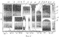
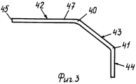
На фиг.1 изображено устройство комплекта измерительных приборов, на фиг.2 - вид сверху, с измерительными приборами, на фиг.3 - съемная крышка.Figure 1 shows the device of a set of measuring instruments, figure 2 is a top view, with measuring instruments, figure 3 is a removable cover.
Устройство состоит из корпуса 1, выполненного в виде короба с открытым верхом и содержащего заднюю стенку 2, боковые стенки 3, переднюю стенку 4, днище 5. Внешняя сторона днища 5 снабжена фиксаторами 6, выполненными в виде продольных полос, расположенных вдоль боковых стенок. Такое выполнение и расположение фиксаторов 6 обеспечивает надежную фиксацию одного устройства относительно другого при установке их друг на друга, что обеспечивает компактность транспортировки и складирования устройства при хранении.The device consists of a housing 1, made in the form of a box with an open top and containing a rear wall 2,
Внутри корпуса 1 размещают съемную панель 7, в которой выполнены разделенные перегородками ложементы в виде углублений. Часть углублений выполнена глухими прямоугольной формы 8, 9, 10 для закрепления амперметров 11, вольтметра 12, секундометра 13, термометра 14. Углубление 15 выполнено также глухим в виде соединенных двух прямоугольников 16, 17, различных по ширине и длине, т.е. боковые стенки углублений имеют ступенку, выполнено ступенчатым для размещения мультиметра с комплексом соединительных проводов 18. Углубление 19 выполнено сквозным и предназначено для размещения элементов питания 20. Углубление 21 выполнено с симметричными ступенчатыми боковыми сторонами 22 для размещения мерного цилиндра с подставкой 23, причем часть углубления, а именно первая ступень 24, выполнена сквозной, а остальные ступени глухими. Углубления 25, 26 и 27 выполнены глухими с одним скругленным торцом и предназначены для размещения динамометра 28, весов 29 и щупа 30 термометра 14. Углубление 31 выполнено глухим с двумя скругленными торцами для размещения измерительной ленты 32. Углубление 33 выполнено в виде продольного щелевого глухого углубления с боковыми выемками 34, выполненными по радиусу и разнесенными по длине щели. В перегородке между углублениями 10 и 27 выполнена желобчатая выемка 35 для размещения спирального провода 36. Высота панели 7 выполнена меньшей, чем высота передней стенки 4. Такое выполнение панели 7 надежно ее фиксирует внутри корпуса и исключает выпадение приборов, размещенных в углублениях. Передний торец 37 боковых стенок 3 корпуса 1 выполнен высотой большей, чем высота передней 4 стенки корпуса, а сама передняя стенка 4 выполнена в размер, соответствующий расстоянию между внешними боковыми поверхностями 38 боковых стенок 3, таким образом образуется площадка, верхний торец передней стенки, для опоры торца крышки 39. Крышка 39 выполнена с двумя перегибами 40 и 41, так что образуется горизонтальный 42, наклонный 43 и вертикальный 44 участки. Свободный торец 45 горизонтального участка 42 входит в паз 46, выполненный на внутренней поверхности задней стенки 2, боковые торцы 47 крышки входят в пазы 48, выполненные на внутренней поверхности боковых стенок 3, а наклонный участок 43 взаимодействует со скошенным углом, т.е. скошенной поверхностью 49 боковых стенок 3. Таким образом, длина горизонтального участка 42 крышки равна длине пазов 48 боковых стенок 3, а длина вертикального участка крышки равна длине выступающих частей 50 передних торцов 37 боковых стенок 3 над верхним торцом 51 передней стенки 4, на этот торец 51 опирается своим нижним свободным торцом 52 крышка 39. Такое выполнение изогнутости крышки 39 и ее взаимодействие с корпусом 1 обеспечивает слегка демпфирующее ее расположение, что способствует ее надежному закреплению в пазах корпуса 1.Inside the housing 1, a removable panel 7 is placed, in which the lodgements in the form of recesses are made separated by partitions. Part of the recesses is made of blind
Перед началом проведения лабораторных работ учащиеся получают устройство комплекта измерительных приборов, располагают его удобно на учебном столе, открывают крышку, слегка выдвигая ее вперед за боковые ее торцы, при этом она сдемпфирует, а ее свободный нижний торец выйдет из взаимодействия с верхним торцом передней стенки. Учащиеся используют необходимые измерительные элементы в конкретном лабораторном задании. Данное устройство позволяет производить свыше тридцати различных измерений по таким курсам как различные разделы физики, химии и биологии.Before starting laboratory work, students receive a device of a set of measuring instruments, place it conveniently on the training table, open the lid, slightly pushing it forward beyond its lateral ends, while it damps, and its free lower end comes out of interaction with the upper end of the front wall. Students use the necessary measuring elements in a specific laboratory task. This device allows you to make over thirty different measurements in such courses as various sections of physics, chemistry and biology.
Предложенное устройство комплекта измерительных приборов позволяет учащимся иметь в наличии все необходимые измерительные приборы при проведении лабораторных работ, быстрый и удобный доступ к необходимому измерительному прибору, надежное закрепление всех приборов в корпусе как при транспортировке, так и при хранении. Устройство собрано в удобный компактный корпус, а выполнение съемной панели делает устройство универсальным. Устройство легко в изготовлении, просто в эксплуатации и компактно в хранении.The proposed device of a set of measuring instruments allows students to have all the necessary measuring instruments available during laboratory work, quick and convenient access to the necessary measuring instrument, and reliable fixing of all instruments in the case both during transportation and during storage. The device is assembled in a convenient compact housing, and the implementation of a removable panel makes the device universal. The device is easy to manufacture, easy to operate and compact in storage.
Claims (1)
Priority Applications (1)
| Application Number | Priority Date | Filing Date | Title |
|---|---|---|---|
| RU2005123710/11A RU2296373C1 (en) | 2005-07-26 | 2005-07-26 | Device of a set of measuring devices |
Applications Claiming Priority (1)
| Application Number | Priority Date | Filing Date | Title |
|---|---|---|---|
| RU2005123710/11A RU2296373C1 (en) | 2005-07-26 | 2005-07-26 | Device of a set of measuring devices |
Publications (1)
| Publication Number | Publication Date |
|---|---|
| RU2296373C1 true RU2296373C1 (en) | 2007-03-27 |
Family
ID=37999275
Family Applications (1)
| Application Number | Title | Priority Date | Filing Date |
|---|---|---|---|
| RU2005123710/11A RU2296373C1 (en) | 2005-07-26 | 2005-07-26 | Device of a set of measuring devices |
Country Status (1)
| Country | Link |
|---|---|
| RU (1) | RU2296373C1 (en) |
Cited By (1)
| Publication number | Priority date | Publication date | Assignee | Title |
|---|---|---|---|---|
| RU201493U1 (en) * | 2020-08-20 | 2020-12-17 | Акционерное общество "Елатомский приборный завод" | Thermometer storage container insert |
Citations (2)
| Publication number | Priority date | Publication date | Assignee | Title |
|---|---|---|---|---|
| FR2601799A3 (en) * | 1986-07-18 | 1988-01-22 | Peuziat Jean Jacques | Multi-role device for individual experiments in basic physical sciences |
| RU2205456C1 (en) * | 2002-06-05 | 2003-05-27 | Федеральное государственное унитарное предприятие "Координационно-аналитический центр по научно-техническим программам Министерства образования Российской Федерации" | Stand for laboratory instruments designed for investigating laws of molecular physics and thermodynamics |
-
2005
- 2005-07-26 RU RU2005123710/11A patent/RU2296373C1/en not_active IP Right Cessation
Patent Citations (2)
| Publication number | Priority date | Publication date | Assignee | Title |
|---|---|---|---|---|
| FR2601799A3 (en) * | 1986-07-18 | 1988-01-22 | Peuziat Jean Jacques | Multi-role device for individual experiments in basic physical sciences |
| RU2205456C1 (en) * | 2002-06-05 | 2003-05-27 | Федеральное государственное унитарное предприятие "Координационно-аналитический центр по научно-техническим программам Министерства образования Российской Федерации" | Stand for laboratory instruments designed for investigating laws of molecular physics and thermodynamics |
Cited By (1)
| Publication number | Priority date | Publication date | Assignee | Title |
|---|---|---|---|---|
| RU201493U1 (en) * | 2020-08-20 | 2020-12-17 | Акционерное общество "Елатомский приборный завод" | Thermometer storage container insert |
Similar Documents
| Publication | Publication Date | Title |
|---|---|---|
| Wiegelmann et al. | Comparing magnetic field extrapolations with measurements of magnetic loops | |
| Teixeira et al. | Experimental determination of the nature of diffusive motions of water molecules at low temperatures | |
| Verde et al. | Early cosmology constrained | |
| IT1141521B (en) | MEASUREMENT PROBE FOR DETERMINING EFFLUENT GAS COMPONENTS | |
| CN108507705A (en) | A kind of chip temperature measuring equipment | |
| Gasparini | Markov chain Monte Carlo in practice | |
| Poznanski et al. | Type II-P supernovae as standard candles: the SDSS-II sample revisited | |
| Wasserstein | Monte Carlo: Concepts, algorithms, and applications | |
| Xi et al. | A direct quantitative Raman method for the measurement of dissolved bisulfate in acid-Sulfate fluids | |
| RU2227329C1 (en) | Device for experimental study of the laws of optics | |
| 張德勝 | The validity and reliability of student ratings: Comparison between paper-pencil and online survey | |
| CN208313474U (en) | A kind of chip temperature measuring equipment | |
| RU2291495C1 (en) | Educational device for studying quantum phenomena | |
| JP2007255896A (en) | Arrangement case and arrangement method | |
| RU2205456C1 (en) | Stand for laboratory instruments designed for investigating laws of molecular physics and thermodynamics | |
| RU101903U1 (en) | X-ray Phantom Phantom | |
| KR101705716B1 (en) | Scale apparatus for surveying | |
| CN205175725U (en) | Visual safety device against wind of dismantlement formula suitable for in grassland resources investigation biomass | |
| CN206504729U (en) | A kind of teaching object staff base and the matched levelling rod used | |
| CN206253151U (en) | A kind of Experiment of Inorganic Chemstry tool box | |
| CN215182669U (en) | An Ultrasound Examination Model Simulating Human Tissue | |
| CN214029734U (en) | Reagent storage device of Karl Fischer coulometry moisture tester | |
| CN202604849U (en) | Nine-hole balance tester | |
| CN205396994U (en) | Surveying instrument portable box | |
| RU176876U1 (en) | Device for assessing the toxicity of water and water extracts of various environments |
Legal Events
| Date | Code | Title | Description |
|---|---|---|---|
| MM4A | The patent is invalid due to non-payment of fees |
Effective date: 20090727 |