RU2294867C2 - Sheet material for making packs for food products and packs made of such material - Google Patents
Sheet material for making packs for food products and packs made of such material Download PDFInfo
- Publication number
- RU2294867C2 RU2294867C2 RU2004116685/12A RU2004116685A RU2294867C2 RU 2294867 C2 RU2294867 C2 RU 2294867C2 RU 2004116685/12 A RU2004116685/12 A RU 2004116685/12A RU 2004116685 A RU2004116685 A RU 2004116685A RU 2294867 C2 RU2294867 C2 RU 2294867C2
- Authority
- RU
- Russia
- Prior art keywords
- mark
- lines
- packaging
- decorative design
- pressing
- Prior art date
Links
Images


Classifications
-
- B—PERFORMING OPERATIONS; TRANSPORTING
- B65—CONVEYING; PACKING; STORING; HANDLING THIN OR FILAMENTARY MATERIAL
- B65D—CONTAINERS FOR STORAGE OR TRANSPORT OF ARTICLES OR MATERIALS, e.g. BAGS, BARRELS, BOTTLES, BOXES, CANS, CARTONS, CRATES, DRUMS, JARS, TANKS, HOPPERS, FORWARDING CONTAINERS; ACCESSORIES, CLOSURES, OR FITTINGS THEREFOR; PACKAGING ELEMENTS; PACKAGES
- B65D65/00—Wrappers or flexible covers; Packaging materials of special type or form
- B65D65/38—Packaging materials of special type or form
-
- B—PERFORMING OPERATIONS; TRANSPORTING
- B65—CONVEYING; PACKING; STORING; HANDLING THIN OR FILAMENTARY MATERIAL
- B65B—MACHINES, APPARATUS OR DEVICES FOR, OR METHODS OF, PACKAGING ARTICLES OR MATERIALS; UNPACKING
- B65B41/00—Supplying or feeding container-forming sheets or wrapping material
- B65B41/18—Registering sheets, blanks, or webs
Abstract
Description
Область техникиTechnical field
Настоящее изобретение относится к листовому материалу для упаковывания пищевых продуктов.The present invention relates to a sheet material for packaging food products.
Предшествующий уровень техникиState of the art
Известны материалы для упаковывания льющихся пищевых продуктов, как например фруктового сока, вина, томатного соуса, пастеризованного молока или молока длительного хранения (молока ультравысокотемпературной обработки (УВТО)).Known materials for packaging pouring food products, such as fruit juice, wine, tomato sauce, pasteurized milk or milk long-term storage (milk ultra-high temperature processing (UHTO)).
Упаковки формируются из непрерывного полотна упаковочного материала. Согласно одному известному способу полотно запечатывают в продольном направлении для образования непрерывной трубы.Packages are formed from a continuous web of packaging material. According to one known method, the web is sealed in the longitudinal direction to form a continuous tube.
Упаковочный материал имеет многослойную структуру, состоящую из слоя бумажного материала, покрытого с обеих сторон слоями термосвариваемого материала, например, полиэтилена, а в случае асептических упаковок для продуктов длительного хранения, как например молока УВТО, также содержит слой барьерного материала, которым является, например, алюминиевая фольга и который наложен на слой термосвариваемой пластмассы и, в свою очередь, покрыт другим слоем термосвариваемой пластмассы, в конце концов, образующим внутреннюю поверхности упаковки, соприкасающуюся с пищевым продуктом.The packaging material has a multilayer structure consisting of a layer of paper material coated on both sides with layers of heat-sealable material, for example, polyethylene, and in the case of aseptic packaging for long-term storage products, such as UVTO milk, also contains a layer of barrier material, which, for example, aluminum foil and which is superimposed on a layer of heat sealable plastic and, in turn, is coated with another layer of heat sealable plastic, finally forming the inner surface of the package, in contact with food.
Для изготовления асептических упаковок полотно упаковочного материала сматывают с рулона и подают через асептическую камеру, в которой его стерилизуют, например, посредством нанесения стерилизующего вещества, как например перекиси водорода, которую затем испаряют, нагревая и/или подвергая упаковочный материал облучению с соответствующей длиной волны и интенсивностью.For the manufacture of aseptic packages, the web of packaging material is wound from a roll and fed through an aseptic chamber in which it is sterilized, for example, by applying a sterilizing substance, such as hydrogen peroxide, which is then vaporized by heating and / or exposing the packaging material to radiation with an appropriate wavelength and intensity.
Затем стерилизованное полотно свертывают в цилиндр и запечатывают в продольном направлении для образования известным способом непрерывной, вертикальной, продольно запечатанной трубы. Иначе говоря, труба из упаковочного материала образует продолжение асептической камеры и непрерывно наполняется льющимся пищевым продуктом и затем подается к устройству для формования и запечатывания отдельных упаковок, на котором парами зажимов поперечно зажимают и запечатывают трубу для формования пакетов в виде подушек.Then the sterilized web is rolled up into a cylinder and sealed in the longitudinal direction to form a continuous, vertical, longitudinally sealed tube in a known manner. In other words, the tube made of packaging material forms a continuation of the aseptic chamber and is continuously filled with pouring food product and then fed to the device for forming and sealing individual packages, on which the tube for forming bags in the form of pillows is transversely clamped and sealed with pairs of clamps.
Затем пакеты в виде подушек разделяют, разрезая участок запечатывания между пакетами, и подают в пункт окончательного формования, где их механически складывают для придания формы готовых упаковок.Then the pillow bags are separated, cutting the sealing area between the bags, and fed to the final molding station, where they are mechanically folded to shape the finished packages.
В процессе изготовления упаковочного материала различные операции выполняют, используя в качестве указателя метку или метки, напечатанные на материала на первой стадии печатания.In the manufacturing process of the packaging material, various operations are performed using as a pointer a mark or marks printed on the material in the first printing step.
Метка или метки включают в себя напечатанный код, который обычно используют также на формовочной машине для контроля подачи материала через различные производственные пункты. Конкретнее, как известно, так называемое устройство «для коррекции декоративного оформления» действует на формуемые упаковки для различной «тяги» материала в направлении подачи и обеспечения выполнения механических операций формования в соответствии с декоративным оформлением на упаковках.The tag or tags include a printed code, which is also commonly used on a molding machine to control the flow of material through various production points. More specifically, as you know, the so-called device for the correction of decorative design "acts on molded packaging for various" traction "of the material in the direction of supply and ensure the execution of mechanical molding operations in accordance with the decorative design on the packaging.
На известных упаковочных машинах до продольного запечатывания полотна для образования трубы обычно необходимо также контролировать поперечное положение полотна, например, для выполнения вспомогательных операций, как например разрезания и нанесения съемных этикеток или устройств для открывания.On known packaging machines, before longitudinally sealing the web to form a pipe, it is usually also necessary to control the lateral position of the web, for example, to perform auxiliary operations, such as cutting and applying removable labels or opening devices.
Кроме того, необходимо контролировать угловое положение трубы на устройстве для запечатывания, которое при использовании этого устройства может изменяться относительно заданного положения вследствие того, что боковые края ленты не являются совершенно прямыми, а также из-за воздействий, вызываемых последовательным ударением пар зажимов о трубку и изменениями в натяжении полотна.In addition, it is necessary to control the angular position of the pipe on the sealing device, which, when using this device, can change relative to the set position due to the fact that the side edges of the tape are not completely straight, and also due to the effects caused by the successive impact of the pair of clamps on the pipe and changes in web tension.
Так как это может отрицательно повлиять на качество продольных и поперечных швов и на точность, с которой формуются упаковки, известные машины снабжены устройствами для регулирования вручную углового положения трубы. Однако такие устройства отнимают сравнительно много времени и могут потребовать остановки машины, сопровождаемой потерей продукции. Кроме того, предложены системы для автоматического регулирования углового положения трубки из упаковочного материала, но они предусматривают использование специальных датчиков для определения положения наложенных друг на друга слоев материала в продольном шве.Since this can adversely affect the quality of longitudinal and transverse welds and the accuracy with which the packages are formed, known machines are equipped with devices for manually adjusting the angular position of the pipe. However, such devices are relatively time-consuming and may require the machine to stop, accompanied by loss of production. In addition, systems have been proposed for automatically controlling the angular position of a tube of packaging material, but they involve the use of special sensors to determine the position of layers of material superimposed on one another in a longitudinal seam.
Описание изобретенияDescription of the invention
Технической задачей настоящего изобретения является создание листового упаковочного материала для изготовления упаковок с пищевыми продуктами, который содержит зрительно обнаруживаемые метки для определения положения материала на машине как в направлении подачи, так и в поперечном направлении.An object of the present invention is to provide a sheet of packaging material for the manufacture of food packaging, which contains visually detectable marks for determining the position of the material on the machine both in the feed direction and in the transverse direction.
Согласно настоящему изобретению предлагается листовой материал для изготовления упаковок с пищевыми продуктами, который содержит ряд линий сгиба и непрерывный ряд зрительно обнаруживаемых меток и отличается тем, что каждая метка содержит, по меньшей мере, два параллельных отрезка, перпендикулярных направлению подачи указанного материала, и наклонный отрезок, расположенный между параллельными отрезками.The present invention proposes a sheet material for the manufacture of food packaging, which contains a series of fold lines and a continuous series of visually detectable marks and is characterized in that each mark contains at least two parallel sections perpendicular to the feed direction of said material and an inclined section located between parallel segments.
Согласно изобретению при подаче материала через машину метки могут быть обнаружены одним или большим числом оптических датчиков для контроля положения ленты на соответствующем производственном участке, которые соединены с устройством обработки сигналов и контроля для управления устройствами, регулирующими положение ленты. Наклонный отрезок вместе с двумя отрезками, поперечными направлению подачи, показывают поперечное положение материала и могут быть использованы для автоматической коррекции как поперечного положения плоской ленты, так и углового положения трубы.According to the invention, when the material is fed through the machine, the tags can be detected by one or more optical sensors for monitoring the position of the tape in the corresponding production area, which are connected to a signal processing and monitoring device for controlling devices that control the position of the tape. The inclined segment along with two segments transverse to the feed direction show the transverse position of the material and can be used to automatically correct both the transverse position of the flat tape and the angular position of the pipe.
Другой проблемой, обычно связанной с известными упаковочными материалами, является следующая проблема.Another problem commonly associated with known packaging materials is the following problem.
Упаковку формуют, сгибая упаковочный материал по линиям сгиба, «выдавленным» в материале. Хотя формование упаковок должно проводиться в соответствии с линиями сгиба, подачу упаковочного материала в формовочную машину обычно контролируют по меткам, напечатанным на материале.The package is formed by bending the packaging material along the fold lines "squeezed out" in the material. Although the packaging must be molded according to the folding lines, the supply of packaging material to the molding machine is usually controlled by the marks printed on the material.
Причина этого заключается в том, что обычное непосредственное оптическое обнаружение линий сгиба по-прежнему создает проблемы, для которых еще не найдено удовлетворительного решения.The reason for this is that conventional direct optical detection of fold lines still creates problems for which a satisfactory solution has not yet been found.
Образование линий сгиба и печатание осуществляют на разных стадиях процесса изготовления материала, так что неизбежны допуски на точное совпадение размеров между этими двумя операциями. Следовательно, использование напечатанных меток в качестве указателей положения для операций, которые должны проводиться в соответствии с линиями сгиба, неизбежно приводит к ошибкам.The formation of folding lines and printing is carried out at different stages of the manufacturing process of the material, so that tolerances for the exact coincidence of sizes between these two operations are inevitable. Consequently, the use of printed marks as position indicators for operations to be carried out in accordance with fold lines inevitably leads to errors.
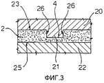
Согласно предпочтительному варианту осуществления изобретения оптически обнаруживаемые метки образованы линиями сгиба, выполненными прессованием и имеющими углубленный профиль на первой поверхности материала и невыпуклый профиль на второй поверхности материала.According to a preferred embodiment of the invention, optically detectable marks are formed by folding lines made by pressing and having a recessed profile on the first surface of the material and a non-convex profile on the second surface of the material.
По сравнению с известными способами образования линий сгиба прессование обеспечивает получение намного более четких линий прессования, которые являются оптически обнаруживаемыми и, следовательно, могут быть использованы в качестве меток.Compared to known methods for forming folding lines, pressing provides much sharper pressing lines that are optically detectable and therefore can be used as marks.
Согласно предпочтительному варианту осуществления изобретения материал, кроме того, содержит декоративное оформление с областью печати, которая, по меньшей мере, частично захватывает одну или большее число образованных прессованием линий сгиба, так что линии сгиба в области печати образуют оптически обнаруживаемые, «негативно-напечатанные» метки.According to a preferred embodiment of the invention, the material further comprises a decoration with a print area that at least partially captures one or more extruded fold lines so that the fold lines in the print area form optically detectable “negatively printed” tags.
При использовании любого известного способа печатания упаковочный материал сдавливают между печатным цилиндром и противоцилиндром. В случае использования обычного способа образования линий сгиба выпуклый профиль линии сгиба со стороны противоцилиндра создает нажим, приводящий к случайному, нежелательному контакту между упаковочным материалом и печатным цилиндром на вогнутой стороне линии сгиба, в результате чего линии сгиба имеют нечеткие профили, которые по существу являются оптически необнаруживаемыми.Using any known printing method, the packaging material is squeezed between the printing cylinder and the counter cylinder. In the case of using the conventional method of forming fold lines, the convex profile of the fold line from the side of the counter cylinder creates a pressure resulting in accidental, undesirable contact between the packaging material and the printing cylinder on the concave side of the fold line, resulting in fold lines having fuzzy profiles that are essentially optically undetectable.
С другой стороны, при образовании линий сгиба прессованием создается плоский или слегка вогнутый профиль линии сгиба на поверхности упаковочного материала, соприкасающейся с противоцилиндром, что, таким образом, исключает создание нажима, и углубленная противоположная сторона линии сгиба определенно является свободной от типографской краски, в результате чего получают сильно контрастную метку, отлично обнаруживаемую оптическим датчиком.On the other hand, when the folding lines are formed by pressing, a flat or slightly concave profile of the folding line is created on the surface of the packaging material in contact with the counter cylinder, which thus eliminates the generation of pressure, and the recessed opposite side of the folding line is definitely free of printing ink, as a result which gives a highly contrasting mark, perfectly detectable by the optical sensor.
Краткое описание чертежейBrief Description of the Drawings
Ряд неограничивающих вариантов осуществления изобретения будет описан в качестве примера со ссылкой на сопровождающие чертежи, на которых:A number of non-limiting embodiments of the invention will be described by way of example with reference to the accompanying drawings, in which:
фиг.1 - схематический вид машины для изготовления асептических упаковок из полотна листового материала согласно настоящему изобретению,figure 1 is a schematic view of a machine for the manufacture of aseptic packaging from a sheet of sheet material according to the present invention,
фиг.2 - часть листового упаковочного материала согласно настоящему изобретению,figure 2 - part of the packaging sheet material according to the present invention,
фиг.3 и 4 - схематический вид соответствующих стадий способа изготовления материала с фиг.2,figure 3 and 4 is a schematic view of the corresponding stages of the method of manufacturing the material of figure 2,
фиг.5 - часть упаковочного материала согласно другому варианту осуществления изобретения.5 is a part of a packaging material according to another embodiment of the invention.
Наилучший вариант осуществления изобретенияBest Mode for Carrying Out the Invention
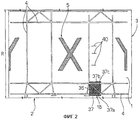
На фиг.2 позицией 1 обозначена часть листового упаковочного материала 2, подаваемого в виде непрерывного полотна 3.2, reference numeral 1 denotes a portion of the
Полотно 3 материала 2 содержит ряд линий сгиба 4 и напечатанное декоративное оформление 5, которые повторяются с интервалами R, равными длине материала, необходимой для изготовления одной упаковки.The
Полотно 3 может быть использовано на машине 6 для изготовления асептических упаковок, которая схематически показана на фиг.1 и на которой полотно 3 сматывают с рулона 7 и подают через асептическую камеру (не показана), где его стерилизуют, и через устройство 8, посредством которого полотно сгибают в продольном направлении и запечатывают для образования известным способом непрерывной вертикальной трубы 9.Canvas 3 can be used on an aseptic packaging machine 6, which is shown schematically in FIG. 1 and on which the
Трубу 9 из упаковочного материала непрерывно наполняют льющимся пищевым продуктом посредством известного наполнительного устройства 10 и затем подают к пункту 14 формования и поперечного запечатывания, где ее зажимают между парами зажимов (не показаны), которые поперечно запечатывают трубу для образования пакетов 15 в форме подушек.A tube 9 of packaging material is continuously filled with a pouring food product by means of a known filling device 10 and then fed to the molding and transverse sealing station 14, where it is clamped between pairs of clamps (not shown) that transverse seal the tube to form pillow-shaped bags 15.
Затем пакеты 15 в форме подушек разделяют, разрезая участок запечатывания между пакетами, и подают на пункт окончательного формования 16, где их механически складывают для придания формы готовых пакетов 17.Then, the pillow-shaped bags 15 are separated, cutting the sealing portion between the bags, and fed to the final molding station 16, where they are mechanically folded to shape the finished bags 17.
Пакеты формуют, сгибая материал по линиям сгиба 4 и контролируя подачу материала посредством оптического датчика 16 для «считывания» меток 18, расположенных на материале с интервалами R.The bags are formed by bending the material along the
Согласно настоящему изобретению каждая метка 18 содержит ломаную, по существу Z-образную линию отметки 37, образованную первым и вторым отрезками 37а, 37b, параллельными друг другу и перпендикулярными направлению подачи полотна 3 в машине 6, и отрезком 37с, наклоненным относительно отрезков 37а, 37b.According to the present invention, each
Следовательно, при подаче полотна 3 через машину 6 метка 18 может быть обнаружена одним или большим числом оптических датчиков 16, которые контролируют положение полотна 3 на соответствующем производственном участке и соединены с устройством обработки сигналов и контроля 41 для управления известными устройствами (не показаны), регулирующими положение полотна 3.Therefore, when the
Используя Z-образную линию отметки 37, можно контролировать положение полотна 3 как в направлении подачи, так и в поперечном направлении, например, для коррекции поперечного положения еще плоского полотна при выполнении вспомогательных операций, как например разрезания и нанесения съемных этикеток и устройств для открывания или для коррекции углового положения трубы 9.Using the Z-shaped line of the
Кроме того, возможен контроль за поперечным выравниванием во время процесса нанесения липкой полоски на один край полотна для продольного запечатывания полотна и образования трубы, а также контроль за выравниванием наложенных один на другой краев полотна в случае сращивания полотен.In addition, it is possible to control lateral alignment during the process of applying an adhesive strip to one edge of the web for longitudinal sealing of the web and the formation of the pipe, as well as to control the alignment of the superimposed web edges in the case of jointing the web.
Оптический датчик 16 фактически успешно обнаруживает первый отрезок 37а, наклонный отрезок 37с и второй отрезок 37b линии; устройство контроля 41 вычисляет первое время Т1 между моментами обнаружения первого отрезка 37а и наклонного отрезка 37с и второе время Т2 между моментами обнаружения наклонного отрезка 37с и второго отрезка 37b; и на основе отношения Т1 и Т2 может быть вычислена и исправлена ошибка в поперечном положении полотна 3. Конкретнее, если датчик 16 расположен в средней плоскости меток 18, то при правильном или стандартном положении полотна 3 правильное поперечное положение полотна соответствует отношению Т1/Т2, равному 1. Если это отношение меньше или больше, чем 1, то полотно может быть известным способом поперечно передвинуто в соответствующем направлении для уменьшения ошибки в положении.The optical sensor 16 actually successfully detects the
Подобным же образом ошибку в поперечном положении полотна 3 можно вычислить по отношению между Т1 или Т2 и суммарным временем Т1+Т2. В этом случае величина 0,5 обозначает центр, в то время как другие величины обозначают поперечные смещения.Similarly, the error in the lateral position of the
Линии сгиба 4 желательно выполнять в виде линий прессования, образованных посредством процесса образования линий сгиба прессованием (фиг.3).The
Конкретнее, материал 2 прессуют между формовочным валиком 20, профиль которого частично показан в плане на фиг.3 и который имеет ряд выступов 21, соответствующих линиям прессования 4, и гладким опорным валиком 22, т.е. не имеющим никаких углублений, соответствующих выступам 21. Желательно, чтобы валик 20 воздействовал на поверхность 23 материала, которая образует наружную поверхность упаковки, т.е. на которой печатают декоративное оформление 5, а валик 22 - на противоположную поверхность 25.More specifically, the
Высота выступов 21 составляет от 50% до 90% и предпочтительно около 80% толщины материала 2. Во время прессования толщина материала уменьшается на аналогичную процентную величину, после чего материал частично восстанавливается, но сохраняет остаточную деформацию прессования. Остаточная глубина линий прессования составляет от 30% до 60% толщины материала 2 и равна около 50% толщины, когда во время образования линий сгиба создается деформация приблизительно в 80%.The height of the
Как ясно показано на фиг.4, линии прессования 4 на поверхности 23 материала имеют углубленный профиль, ограниченный по бокам стенками 26, а на противоположной поверхности 25 по существу плоский или слегка вогнутый профиль.As clearly shown in FIG. 4, the
Кроме того, на фиг.4 схематически показаны в плане профили печатного валика 30 и противовалика 31, соответственно соприкасающиеся с поверхностями 23 и 25 материала 2 у линии прессования 4.In addition, figure 4 schematically shows in plan a profile of the
Как ясно показано на фиг.4, по существу плоский или слегка вогнутый профиль линии прессования 4 на стороне, обращенной к противовалику 31, исключает нажим на материал 2, который может привести к соприкосновению более тонкой части материала с печатным валиком 30.As clearly shown in FIG. 4, a substantially flat or slightly concave profile of the
Следовательно, печатный валик 30 соприкасается только с поверхностью материала 2 снаружи линии прессования 4, которая, таким образом, выглядит на материале как «негативно-напечатанная» линия.Therefore, the
В предпочтительном варианте осуществления настоящего изобретения эта особенность образования линий сгиба прессованием может быть использована для получения меток 18, совершенно соответствующих линиям прессования 4. Например, как показано на фиг.2, метка 18 может быть образована прямоугольным участком 36, напечатанным на части материала 2, в конце концов образующей дно готовой упаковки 17. Участок 36 заключает в себе часть линий прессования 4, в частности, Z-образную линию 37, образованную отрезками 37а, 37b, 37с линий прессования 4, так чтобы создавать метку 18 с линией 37 и в контрасте с ней.In a preferred embodiment of the present invention, this feature of forming press folding lines can be used to produce
Таким образом, Z-образная линия 37 является «негативно-напечатанной» на участке 36, образующим часть декоративного оформления 5.Thus, the Z-shaped
Материал 2 (фиг.2) с пользой снабжен оптически обнаруживаемыми знаками 40 для их считывания оптическим датчиком 16 для того, чтобы нельзя было «спутать» метку 18 (которая дает три переменно разнесенных отсчета) с другими знаками, образованными декоративным оформлением 5, линиями 4 или их сочетаниями.Material 2 (FIG. 2) is advantageously equipped with optically
Знаки 40, которые могут быть напечатаны или выдавлены, могут быть образованы штрих-кодом или двумя или большим числом линий, перпендикулярных к направлению подачи и расположенных на заранее установленном расстоянии друг от друга. Штрих-код может быть расположен в любом удобном месте на ленте.The
Устройство 41 для обработки сигналов может быть запрограммировано на открывание считывающего окна (выполненного с такими размерами, чтобы полностью считывать метку 18) только после заранее установленного интервала времени и/или расстояния с того времени, как считана известная последовательность знаков 40 с заданным шагом между ними.The signal processing device 41 can be programmed to open a reading window (configured to read the
В варианте на фиг.5 метка 18 образована линиями прессования 4, выполненными лишь с этой целью, т.е. не играющими никакой роли в формовании упаковки, и с пользой представляет собой квадратный напечатанный участок 36, который содержит четыре линии прессования 37d, образующими квадрат, и линию прессования 37е по диагонали квадрата.In the embodiment of FIG. 5, the
Таким образом, метку можно «считывать» точно таким же самым способом, как Z-образную линию 37, но, будучи квадратной, она может быть считана в двух перпендикулярных направлениях подачи материала Х, У относительно оптического датчика 16.Thus, the mark can be “read” in exactly the same way as the Z-shaped
Например, может оказаться полезным применение метки 18 в качестве базы отсчета на устройстве по нанесению устройств для открывания на готовые упаковки 17, в котором упаковки подаются вперед при их разной ориентации.For example, it may be useful to use the
Ясно, что могут быть сделаны изменения в вышеописанном материале, при этом, однако, не выходя за пределы, определенные в сопровождающей формуле изобретения.It is clear that changes can be made to the above material, however, without going beyond the limits defined in the accompanying claims.
В частности, если контраст, получаемый вследствие образования линий сгиба прессованием, является достаточным, то напечатанный участок 36 может отсутствовать и линии сгиба считываются непосредственно.In particular, if the contrast obtained due to the formation of the folding lines by pressing is sufficient, then the printed
Кроме того, в противоположность образованию линий сгиба прессованием материал может быть снабжен метками Z-образной формы или в форме квадрата с диагональю, позитивно или негативно напечатанными обычным способом.In addition, in contrast to the formation of fold lines by compression, the material can be provided with Z-shaped or square-shaped labels with a diagonal positively or negatively printed in the usual way.
Claims (15)
Applications Claiming Priority (2)
| Application Number | Priority Date | Filing Date | Title |
|---|---|---|---|
| ITTO2001A001045 | 2001-11-02 | ||
| IT2001TO001045A ITTO20011045A1 (en) | 2001-11-02 | 2001-11-02 | SHEET MATERIAL FOR THE PRODUCTION OF PACKAGES OF FOOD PRODUCTS, AND PACKAGES MADE WITH SUCH MATERIAL. |
Publications (2)
| Publication Number | Publication Date |
|---|---|
| RU2004116685A RU2004116685A (en) | 2005-03-27 |
| RU2294867C2 true RU2294867C2 (en) | 2007-03-10 |
Family
ID=11459285
Family Applications (1)
| Application Number | Title | Priority Date | Filing Date |
|---|---|---|---|
| RU2004116685/12A RU2294867C2 (en) | 2001-11-02 | 2002-10-31 | Sheet material for making packs for food products and packs made of such material |
Country Status (16)
| Country | Link |
|---|---|
| US (1) | US7521075B2 (en) |
| EP (1) | EP1441954B1 (en) |
| JP (1) | JP2005510414A (en) |
| KR (1) | KR100944612B1 (en) |
| CN (1) | CN1241788C (en) |
| AT (1) | ATE301074T1 (en) |
| BR (1) | BR0212240A (en) |
| DE (1) | DE60205399T2 (en) |
| ES (1) | ES2246417T3 (en) |
| HK (1) | HK1074193A1 (en) |
| HU (1) | HUP0401288A3 (en) |
| IT (1) | ITTO20011045A1 (en) |
| MX (1) | MXPA04002061A (en) |
| RU (1) | RU2294867C2 (en) |
| UA (1) | UA77016C2 (en) |
| WO (1) | WO2003037722A1 (en) |
Families Citing this family (18)
| Publication number | Priority date | Publication date | Assignee | Title |
|---|---|---|---|---|
| EP1785358B1 (en) | 2005-11-15 | 2010-05-12 | Tetra Laval Holdings & Finance SA | Sheet packaging material with register mark |
| EP2115543B1 (en) * | 2007-01-11 | 2012-10-31 | 3M Innovative Properties Company | Web longitudinal position sensor |
| JP2010530544A (en) * | 2007-06-19 | 2010-09-09 | スリーエム イノベイティブ プロパティズ カンパニー | Total reflection displacement scale |
| JP2010532466A (en) * | 2007-06-19 | 2010-10-07 | スリーエム イノベイティブ プロパティズ カンパニー | System and method for displaying web position |
| EP2162705A4 (en) * | 2007-06-19 | 2014-02-19 | 3M Innovative Properties Co | Systems and methods for fabricating displacement scales |
| JP4853440B2 (en) * | 2007-09-26 | 2012-01-11 | 富士ゼロックス株式会社 | Printing system |
| US8185036B2 (en) | 2008-03-21 | 2012-05-22 | Fuji Xerox Co., Ltd. | Medium transport apparatus, image forming apparatus and medium transport method |
| JP4650507B2 (en) * | 2008-03-21 | 2011-03-16 | 富士ゼロックス株式会社 | Medium conveying apparatus and image forming apparatus |
| US8847185B2 (en) | 2008-12-29 | 2014-09-30 | 3M Innovative Properties Company | Phase-locked web position signal using web fiducials |
| KR101578259B1 (en) | 2008-12-30 | 2015-12-16 | 쓰리엠 이노베이티브 프로퍼티즈 컴파니 | Apparatus and method for making fiducials on a substrate |
| EP2658724A4 (en) * | 2010-12-29 | 2016-12-21 | Tetra Laval Holdings & Finance | A method of producing a packaging material provided with a recurring pattern of print ink |
| AU2012264931A1 (en) * | 2011-05-31 | 2013-12-12 | Tetra Laval Holdings & Finance S.A. | A packaging material having a detectable mark for manufactoring of carton or paperboard based packaging containers |
| CN102633053A (en) * | 2012-04-24 | 2012-08-15 | 温剑 | Method for producing moon cake filling packaging bag without adhering adhesive label |
| JP6352698B2 (en) * | 2014-06-30 | 2018-07-04 | 日本テトラパック株式会社 | Packaging materials and packaging filling equipment |
| EP3081497B1 (en) * | 2015-04-14 | 2018-03-14 | Tetra Laval Holdings & Finance SA | Packaging machine and method for producing packages from a packaging material |
| EP3141488B1 (en) * | 2015-09-09 | 2020-04-22 | Tetra Laval Holdings & Finance S.A. | Packaging machine for producing packages from a sheet of packaging material |
| RU2762878C1 (en) * | 2017-12-15 | 2021-12-23 | Тетра Лаваль Холдингз Энд Файнэнс С.А. | Packaging material for liquid food products, system and method for application of opening to packaging material |
| WO2020127018A1 (en) * | 2018-12-21 | 2020-06-25 | Tetra Laval Holdings & Finance S.A. | A method for printing a web of packaging material and an apparatus thereof |
Family Cites Families (28)
| Publication number | Priority date | Publication date | Assignee | Title |
|---|---|---|---|---|
| US2483155A (en) * | 1946-01-16 | 1949-09-27 | Ivers Lee Co | Alignment controlling packaging machine |
| US3028064A (en) * | 1959-08-19 | 1962-04-03 | Hansella Werke Albert Henkel A | Control device for web feeding mechanism |
| US3220320A (en) * | 1962-07-24 | 1965-11-30 | Continental Can Co | Apparatus for manufacturing spirally wound containers |
| US3276183A (en) * | 1963-03-22 | 1966-10-04 | Diamond Crystal Salt Co | Register control device for packaging apparatus |
| US3453799A (en) * | 1965-09-01 | 1969-07-08 | Cloud Machine Corp | Manufacture of sealed packages from strip stock |
| US3497576A (en) * | 1969-03-17 | 1970-02-24 | Bausch & Lomb | Method for permanently imprinting an identification mark in the surface of a heat-softenable material |
| SE362824B (en) * | 1971-11-25 | 1973-12-27 | Tetra Pak Int | |
| US4184700A (en) * | 1975-11-17 | 1980-01-22 | Lgz Landis & Gyr Zug Ag | Documents embossed with optical markings representing genuineness information |
| SE400523B (en) * | 1975-12-19 | 1978-04-03 | Ziristor Ab | SEE THAT AT A PACKAGING MACHINE READ PHOTO CELL MARKINGS ON THE DECORAGE SIDE OF A MATERIAL PATH AND A DEVICE FOR PERFORMING THE KIT |
| FR2377661A1 (en) * | 1977-01-14 | 1978-08-11 | Roland Emballages | Adjusting lateral position of moving supports - utilising opto-electronic elements providing correction signal from zones of different luminosity |
| US4329573A (en) * | 1980-04-18 | 1982-05-11 | Greene Leonard B | Coded optical identification system |
| US4545780A (en) * | 1982-05-12 | 1985-10-08 | Martin William E | Apparatus and method of making cartons |
| SE454168B (en) * | 1982-09-27 | 1988-04-11 | Tetra Pak Ab | SET AND DEVICE FOR DOSING OF FILLED GOODS IN THE MANUFACTURE OF PACKAGING CONTAINERS |
| US4625101A (en) * | 1984-02-27 | 1986-11-25 | The Goodyear Tire & Rubber Company | Bar code configuration and method of molding |
| US4775169A (en) * | 1986-10-06 | 1988-10-04 | Barth Thomas M | Pre-lined art sheet member |
| ATE98795T1 (en) * | 1988-09-30 | 1994-01-15 | Landis & Gyr Business Support | DIFFRACTION ELEMENT. |
| ATE125967T1 (en) * | 1988-09-30 | 1995-08-15 | Landis & Gry Tech Innovat Ag | BAR CODE PANEL AND BAR CODE READER. |
| IT1240311B (en) * | 1989-12-29 | 1993-12-07 | Cavanna Spa | PROCEDURE TO CHECK THE ADVANCE OF THE WINDING FILM IN WRAPPING MACHINES AND RELATED WRAPPING MACHINE |
| SE468841B (en) * | 1991-08-08 | 1993-03-29 | Tetra Alfa Holdings | EQUIPMENT WITH ELASTIC MATERIAL IN THE HON PART |
| US5393967A (en) * | 1993-07-21 | 1995-02-28 | Sensis Corporation | Method and apparatus for non-contact reading of a relief pattern |
| ITBO940153A1 (en) * | 1994-04-12 | 1995-10-12 | Gd Spa | METHOD FOR OPTICAL CONTROL OF PRODUCTS. |
| JP4096112B2 (en) * | 1995-09-11 | 2008-06-04 | 四国化工機株式会社 | Web alignment device |
| JPH09188357A (en) * | 1995-12-29 | 1997-07-22 | Nippon Tetrapack Kk | Packaging material and packaging container including invisible information and charging and packaging method thereof |
| JPH09236487A (en) * | 1996-02-29 | 1997-09-09 | New Japan Radio Co Ltd | Method for inspecting cover tape of embossed tape |
| DE19646720C2 (en) * | 1996-11-12 | 1999-02-18 | Ina Matallana Kielmann | Method for comparing peak representations, especially Western blot or dot blot strips |
| TW466203B (en) * | 1999-07-07 | 2001-12-01 | Tetra Laval Holdings & Amp Fin | Filling machine |
| EP1116659A1 (en) * | 2000-01-17 | 2001-07-18 | Tetra Laval Holdings & Finance Sa | Packaging machine for producing sealed packages of pourable food products |
| ITTO20011043A1 (en) | 2001-11-02 | 2003-05-02 | Tetra Laval Holdings E Finance | SHEET PACKAGING MATERIAL FOR THE PACKAGING OF VERSABLE FOOD PRODUCTS. |
-
2001
- 2001-11-02 IT IT2001TO001045A patent/ITTO20011045A1/en unknown
-
2002
- 2002-10-31 WO PCT/EP2002/012209 patent/WO2003037722A1/en active IP Right Grant
- 2002-10-31 CN CNB028216547A patent/CN1241788C/en not_active Expired - Fee Related
- 2002-10-31 AT AT02785352T patent/ATE301074T1/en not_active IP Right Cessation
- 2002-10-31 MX MXPA04002061A patent/MXPA04002061A/en active IP Right Grant
- 2002-10-31 ES ES02785352T patent/ES2246417T3/en not_active Expired - Lifetime
- 2002-10-31 DE DE60205399T patent/DE60205399T2/en not_active Expired - Lifetime
- 2002-10-31 RU RU2004116685/12A patent/RU2294867C2/en not_active IP Right Cessation
- 2002-10-31 UA UA20040403253A patent/UA77016C2/en unknown
- 2002-10-31 EP EP02785352A patent/EP1441954B1/en not_active Expired - Lifetime
- 2002-10-31 US US10/488,768 patent/US7521075B2/en not_active Expired - Fee Related
- 2002-10-31 BR BR0212240-5A patent/BR0212240A/en active Search and Examination
- 2002-10-31 JP JP2003540022A patent/JP2005510414A/en active Pending
- 2002-10-31 KR KR1020047004962A patent/KR100944612B1/en not_active IP Right Cessation
- 2002-10-31 HU HU0401288A patent/HUP0401288A3/en unknown
-
2005
- 2005-08-04 HK HK05106723A patent/HK1074193A1/en not_active IP Right Cessation
Also Published As
| Publication number | Publication date |
|---|---|
| DE60205399T2 (en) | 2006-04-20 |
| HK1074193A1 (en) | 2005-11-04 |
| CN1241788C (en) | 2006-02-15 |
| EP1441954A1 (en) | 2004-08-04 |
| US20040197443A1 (en) | 2004-10-07 |
| HUP0401288A3 (en) | 2005-11-28 |
| ITTO20011045A1 (en) | 2003-05-02 |
| KR100944612B1 (en) | 2010-02-26 |
| UA77016C2 (en) | 2006-10-16 |
| ES2246417T3 (en) | 2006-02-16 |
| RU2004116685A (en) | 2005-03-27 |
| WO2003037722A1 (en) | 2003-05-08 |
| US7521075B2 (en) | 2009-04-21 |
| ATE301074T1 (en) | 2005-08-15 |
| BR0212240A (en) | 2004-10-05 |
| MXPA04002061A (en) | 2004-07-08 |
| JP2005510414A (en) | 2005-04-21 |
| CN1578744A (en) | 2005-02-09 |
| HUP0401288A2 (en) | 2004-11-29 |
| EP1441954B1 (en) | 2005-08-03 |
| DE60205399D1 (en) | 2005-09-08 |
| KR20050041998A (en) | 2005-05-04 |
Similar Documents
| Publication | Publication Date | Title |
|---|---|---|
| RU2294867C2 (en) | Sheet material for making packs for food products and packs made of such material | |
| RU2445244C2 (en) | Method of producing sealed packages of fluid food products and packing equipment to this end | |
| JP2594793B2 (en) | Manufacturing method of packaging container | |
| RU2608688C2 (en) | Packaging material having detectable mark for manufacturing carton or paperboard based packaging containers | |
| RU2167765C2 (en) | Method of and device for making foil bags | |
| JP4181993B2 (en) | Packaging sheet material for packaging pourable food | |
| CN102216054B (en) | Equipment and the method for the position in the web of packaging material for food is applied to for detecting sealing strip | |
| JP4965792B2 (en) | Machine for packaging fluid food | |
| EP0936150B1 (en) | Pre-creased packaging sheet material for packaging pourable food products, and packages obtained thereby | |
| ITTO20011044A1 (en) | TAPE MATERIAL FOR THE PACKAGING OF FOOD PRODUCTS. | |
| CN1675056B (en) | Packaging, blank therefor and method for the production thereof | |
| JPH0558965B2 (en) | ||
| JP2012035467A (en) | Apparatus and method for making bag |
Legal Events
| Date | Code | Title | Description |
|---|---|---|---|
| MM4A | The patent is invalid due to non-payment of fees |
Effective date: 20111101 |