RU2291742C2 - Method and the device for transportation of the solid products in the form of particles between the areas with the different pressure - Google Patents
Method and the device for transportation of the solid products in the form of particles between the areas with the different pressure Download PDFInfo
- Publication number
- RU2291742C2 RU2291742C2 RU2004107132/15A RU2004107132A RU2291742C2 RU 2291742 C2 RU2291742 C2 RU 2291742C2 RU 2004107132/15 A RU2004107132/15 A RU 2004107132/15A RU 2004107132 A RU2004107132 A RU 2004107132A RU 2291742 C2 RU2291742 C2 RU 2291742C2
- Authority
- RU
- Russia
- Prior art keywords
- product
- pressure
- lock chamber
- zone
- pneumatic
- Prior art date
Links
Images


Classifications
-
- C—CHEMISTRY; METALLURGY
- C10—PETROLEUM, GAS OR COKE INDUSTRIES; TECHNICAL GASES CONTAINING CARBON MONOXIDE; FUELS; LUBRICANTS; PEAT
- C10J—PRODUCTION OF PRODUCER GAS, WATER-GAS, SYNTHESIS GAS FROM SOLID CARBONACEOUS MATERIAL, OR MIXTURES CONTAINING THESE GASES; CARBURETTING AIR OR OTHER GASES
- C10J3/00—Production of combustible gases containing carbon monoxide from solid carbonaceous fuels
- C10J3/46—Gasification of granular or pulverulent flues in suspension
- C10J3/48—Apparatus; Plants
- C10J3/50—Fuel charging devices
- C10J3/503—Fuel charging devices for gasifiers with stationary fluidised bed
-
- B—PERFORMING OPERATIONS; TRANSPORTING
- B65—CONVEYING; PACKING; STORING; HANDLING THIN OR FILAMENTARY MATERIAL
- B65G—TRANSPORT OR STORAGE DEVICES, e.g. CONVEYORS FOR LOADING OR TIPPING, SHOP CONVEYOR SYSTEMS OR PNEUMATIC TUBE CONVEYORS
- B65G53/00—Conveying materials in bulk through troughs, pipes or tubes by floating the materials or by flow of gas, liquid or foam
- B65G53/34—Details
- B65G53/40—Feeding or discharging devices
- B65G53/48—Screws or like rotary conveyors
-
- C—CHEMISTRY; METALLURGY
- C10—PETROLEUM, GAS OR COKE INDUSTRIES; TECHNICAL GASES CONTAINING CARBON MONOXIDE; FUELS; LUBRICANTS; PEAT
- C10J—PRODUCTION OF PRODUCER GAS, WATER-GAS, SYNTHESIS GAS FROM SOLID CARBONACEOUS MATERIAL, OR MIXTURES CONTAINING THESE GASES; CARBURETTING AIR OR OTHER GASES
- C10J2200/00—Details of gasification apparatus
- C10J2200/15—Details of feeding means
- C10J2200/154—Pushing devices, e.g. pistons
-
- C—CHEMISTRY; METALLURGY
- C10—PETROLEUM, GAS OR COKE INDUSTRIES; TECHNICAL GASES CONTAINING CARBON MONOXIDE; FUELS; LUBRICANTS; PEAT
- C10J—PRODUCTION OF PRODUCER GAS, WATER-GAS, SYNTHESIS GAS FROM SOLID CARBONACEOUS MATERIAL, OR MIXTURES CONTAINING THESE GASES; CARBURETTING AIR OR OTHER GASES
- C10J2200/00—Details of gasification apparatus
- C10J2200/15—Details of feeding means
- C10J2200/156—Sluices, e.g. mechanical sluices for preventing escape of gas through the feed inlet
-
- C—CHEMISTRY; METALLURGY
- C10—PETROLEUM, GAS OR COKE INDUSTRIES; TECHNICAL GASES CONTAINING CARBON MONOXIDE; FUELS; LUBRICANTS; PEAT
- C10J—PRODUCTION OF PRODUCER GAS, WATER-GAS, SYNTHESIS GAS FROM SOLID CARBONACEOUS MATERIAL, OR MIXTURES CONTAINING THESE GASES; CARBURETTING AIR OR OTHER GASES
- C10J2200/00—Details of gasification apparatus
- C10J2200/15—Details of feeding means
- C10J2200/158—Screws
Landscapes
- Chemical & Material Sciences (AREA)
- Engineering & Computer Science (AREA)
- Mechanical Engineering (AREA)
- Combustion & Propulsion (AREA)
- Oil, Petroleum & Natural Gas (AREA)
- Organic Chemistry (AREA)
- Filling Or Emptying Of Bunkers, Hoppers, And Tanks (AREA)
- Feeding, Discharge, Calcimining, Fusing, And Gas-Generation Devices (AREA)
- Physical Or Chemical Processes And Apparatus (AREA)
- Screw Conveyors (AREA)
- Medical Preparation Storing Or Oral Administration Devices (AREA)
- Medicinal Preparation (AREA)
- Branching, Merging, And Special Transfer Between Conveyors (AREA)
- Control And Other Processes For Unpacking Of Materials (AREA)
- Transition And Organic Metals Composition Catalysts For Addition Polymerization (AREA)
Abstract
Description
Изобретение относится к способу и устройству для транспортировки продуктов в форме частиц между зонами с различным давлением.The invention relates to a method and apparatus for transporting particles in the form of particles between zones with different pressures.
Настоящее изобретение является особенно пригодным для транспортировки биомассы с низкой плотностью, такой как солома, но не ограничивается этим.The present invention is particularly suitable for transporting, but is not limited to, low density biomass such as straw.
Способ согласно настоящему изобретению основывается на использовании шлюзовой системы, в соответствии с которой продукт сначала переносится через порционирующее устройство, которое обеспечивает последовательность однородных порций продукта, разделенных однородными, не содержащими частиц областями пространства, а затем порции продукта переносятся по отдельности через шлюзовое устройство, которое содержит, по меньшей мере, одну шлюзовую камеру и два пневматических затвора, из которых, по меньшей мере, один, в любой момент времени, обеспечивает герметичный барьер между двумя зонами с различным давлением, и порции продукта принудительно загружаются из первой зоны в шлюзовую камеру посредством прессующего шнека, ось которого находится по существу на одной линии с осью шлюзовой камеры, и порции продукта принудительно выгружаются из шлюзовой камеры во вторую зону с заданным давлением посредством прессующего шнека или поршня, или посредством газа, пара или жидкости, подаваемой под давлением, более высоким, чем давление во второй зоне.The method according to the present invention is based on the use of a gateway system, in which the product is first transferred through a portioning device that provides a sequence of homogeneous portions of the product separated by homogeneous, particle-free areas of space, and then portions of the product are transferred separately through the gateway device, which contains at least one lock chamber and two pneumatic shutters, of which at least one, at any time, both seals a tight barrier between two zones with different pressures, and portions of the product are forcibly loaded from the first zone into the lock chamber by means of a press screw, the axis of which is essentially in line with the axis of the lock chamber, and portions of the product are forcibly unloaded from the lock chamber into the second zone with a predetermined pressure by means of a pressing screw or piston, or by means of a gas, steam or liquid supplied under pressure higher than the pressure in the second zone.
Прессующий шнек в этом контексте означает шнековый конвейер, который дополнительно может совершать возвратно-поступательное движение по оси, независимое от вращения. Пример прессующего шнека описан в патенте Швеции SE 469536.Compression screw in this context means a screw conveyor, which can optionally reciprocate along the axis, independent of rotation. An example of a pressing screw is described in Swedish patent SE 469536.
Шлюзовая система в этом контексте означает порционирующее устройство, соединенное со шлюзовым устройством. Шлюзовое устройство означает шлюзовая камера, соединенная с пневматическими затворами.A gateway system in this context means a portioning device connected to a gateway device. Airlock means a lock chamber connected to pneumatic valves.
Шлюзовая камера согласно настоящему изобретению представляет собой камеру, которая попеременно может быть соединена с одной из двух зон с различным давлением, при этом камера является герметичной, отделенной от другой зоны под давлением. Устройства, которые в замкнутых условиях обеспечивают герметичное разделение, в дальнейшем будут называться пневматическими затворами.The lock chamber according to the present invention is a chamber that can alternately be connected to one of two zones with different pressures, the chamber being hermetic, separated from the other zone under pressure. Devices that provide tight separation in closed conditions will hereinafter be called pneumatic valves.
Средства для принудительной загрузки/выгрузки загружаются/разгружаются путем положительного переноса продукта, что означает, что прилагаются другие силы для переноса, чем сила тяжести.Means for forced loading / unloading are loaded / unloaded by positive transfer of the product, which means that other forces are applied for the transfer than gravity.
Предпосылки изобретенияBACKGROUND OF THE INVENTION
Существует повышенный интерес к получению энергии из целлюлозы, этанола и других продуктов из биологической массы. Это означает, в том числе, что биомасса подвергается воздействию процессов, осуществляемых при повышенном давлении, таких как обработка паром, гидролиз, экстракция растворителями, варка целлюлозы, термомеханическое получение древесной массы, газификация, сушка с помощью перегретого пара. Биомасса может содержать сухие или влажные частицы, или частицы, суспендированные в жидкости.There is an increased interest in obtaining energy from cellulose, ethanol and other products from biological mass. This means, inter alia, that biomass is exposed to processes carried out at elevated pressure, such as steam treatment, hydrolysis, solvent extraction, pulping, thermomechanical pulping, gasification, and drying using superheated steam. Biomass may contain dry or wet particles, or particles suspended in a liquid.
Для достижения наименьших возможных затрат на производство, является критичным создание надежных непрерывных процессов и непрерывного производства в течение всего года.To achieve the lowest possible costs of production, it is critical to create reliable continuous processes and continuous production throughout the year.
Солома представляет собой большой ресурс биомассы, которая еще не использовалась интенсивно, поскольку ее свойства делают очень сложной ее транспортировку в оборудование, находящееся под давлением, через него и из него. Основными препятствиями являются следующие:Straw is a large biomass resource that has not yet been used intensively, because its properties make it very difficult to transport it to equipment under pressure through and out of it. The main obstacles are the following:
Солома имеет низкую плотность (произвольно измельченная солома имеет плотность примерно 50 кг/м3).The straw has a low density (randomly chopped straw has a density of about 50 kg / m 3 ).
Солома представляет собой несыпучий продукт и имеет очень сильные свойства образования связей.Straw is a loose product and has very strong bonding properties.
Солома имеет высокое содержание абразивного кремния.Straw has a high abrasive silicon content.
Эти препятствия означают, что способ и устройства, имеющие дело с соломой, в связи с герметичным оборудованием будут иметь дело со всем остальным, например древесной стружкой, углем, бытовым мусором, субпродуктами от скотобоен и тому подобное.These obstacles mean that the method and devices dealing with straw, in connection with pressurized equipment, will deal with everything else, such as wood shavings, coal, household waste, by-products from slaughterhouses and the like.
Чтобы быть надежным, устройство должно удовлетворять следующим требованиям:To be reliable, the device must meet the following requirements:
- движущиеся детали должны только до очень ограниченной степени "врезаться" в продукт для предотвращения износа и заеданий.- Moving parts should only “crash” into the product to a very limited extent to prevent wear and jam.
- риск образования связей должен быть устранен путем принудительного перемещения продукта через критические зоны. Это означает, что принудительная загрузка и разгрузка шлюзовых камер являются абсолютно необходимыми.- the risk of forming bonds must be eliminated by forcibly moving the product through critical zones. This means that forced loading and unloading of the gateway cameras are absolutely necessary.
- должна обеспечиваться возможность для сжатия продуктов низкой плотности до более высокой плотности для получения соответствующей производительности при разумных размерах.- it should be possible to compress low-density products to a higher density to obtain appropriate performance at reasonable sizes.
Ни один из известных способов и устройств, основанных на шлюзовых устройствах, не удовлетворяют этим требованиям.None of the known methods and devices based on gateway devices satisfy these requirements.
В патенте Швеции SE 469536 описана камера, в которую продукт переносится с помощью прессующего шнека. На входе цилиндрический нож скользит вперед и врезается в продукт, чтобы закрыть вход, но его функция заключается в том, чтобы закрывать продукт, а не создавать пневматический затвор. На выходе существует пневматический затвор, но поскольку он только один, все это не является шлюзовым устройством, как определено ранее. Устройство представляет собой прессующее проточное устройство для подачи, основанное на способности сильного сжатого слоя продукта понижать утечку газа, когда пневматический затвор открыт.Swedish Patent SE 469536 describes a chamber into which a product is transferred using a compression screw. At the inlet, a cylindrical knife slides forward and cuts into the product to close the inlet, but its function is to close the product, rather than create a pneumatic shutter. There is a pneumatic shutter at the output, but since it is only one, all this is not a gateway device, as previously defined. The device is a flow-through pressing feed device based on the ability of a strong compressed product layer to reduce gas leakage when the pneumatic shutter is open.
Вращающиеся затворы описаны, например, в патенте США №5114053, где ротор, содержащий несколько карманов, вращается непрерывно в цилиндрическом корпусе, причем продукт требуется с очень хорошими свойствами сыпучести. Движущиеся детали должны "врезаться" в продукт, что является проблематичным, в особенности, на входе. Продукт не может быть сжат, и принудительная загрузка/выгрузка является невозможной.Rotary locks are described, for example, in US Pat. No. 5,114,053, where a rotor containing several pockets rotates continuously in a cylindrical housing, the product being required with very good flow properties. Moving parts must “crash” into the product, which is problematic, especially at the inlet. The product cannot be compressed, and forced loading / unloading is not possible.
В патенте Дании 2426035 описан ротор с одной шлюзовой камерой, который вращается попеременно, обеспечивая возможность для поочередного соединения отверстия с зонами высокого и низкого давления. Поршень в шлюзовой камере обеспечивает принудительную выгрузку из шлюзовой камеры и предотвращает выброс из зоны высокого давления. Продукт не загружается в шлюзовую камеру принудительно, поэтому он не может сжиматься, и движущиеся детали должны "врезаться" в продукт.Danish patent 2426035 describes a rotor with a single lock chamber, which rotates alternately, making it possible to alternately connect the bore to high and low pressure zones. The piston in the lock chamber provides for unloading from the lock chamber and prevents the release from the high-pressure zone. The product is not forced into the airlock, so it cannot be compressed, and moving parts must "crash" into the product.
В патенте США 5095825 описан способ, в котором используется ротор, имеющий две шлюзовые камеры, которые принудительно разгружаются с помощью поршней, размещенных в шлюзовых камерах. Отверстия шлюзовых камер расположены на одном конце ротора, так что каждое из них будет соединяться с одной из двух зон с различным давлением, когда ротор останавливается. Согласно этому способу уменьшается риск образования связей во время загрузки шлюзовой камеры путем создания вакуума с помощью поршня. Это означает, что риск образования связей уменьшается только частично, если продукт является проницаемым для воздуха. Движущиеся детали должны "врезаться" в продукт, и с помощью этого способа сжатие продукта является невозможным.US Pat. No. 5,095,825 describes a method in which a rotor is used having two lock chambers, which are forcibly unloaded by pistons located in the lock chambers. The openings of the lock chambers are located at one end of the rotor, so that each of them will be connected to one of two zones with different pressures when the rotor stops. According to this method, the risk of forming bonds during loading of the lock chamber by creating a vacuum using a piston is reduced. This means that the risk of bonding is only partially reduced if the product is permeable to air. Moving parts must "crash" into the product, and using this method, compressing the product is not possible.
В патенте США №5819992 описан ротор с несколькими параллельными шлюзовыми камерами. Шлюзовые камеры имеют вход на одном конце и выход на другом конце. Когда ротор останавливается для загрузки одной шлюзовой камеры и разгрузки другой, герметичная изоляция обеспечивается путем расширения динамических уплотнительных колец. Когда операция загрузки/разгрузки заканчивается, динамические уплотнительные кольца сжимаются, после чего ротор может перемещаться на следующую позицию с меньшим трением, но с неполной герметизацией. Способ не включает в себя порционирование, так что движущиеся детали должны "врезаться" в продукт. Кроме того, данный способ не включает принудительную загрузку, возможность для сжатия или принудительной выгрузки.US Pat. No. 5819992 describes a rotor with several parallel lock chambers. The gateway cameras have an input at one end and an output at the other end. When the rotor stops to load one lock chamber and unload the other, tight insulation is ensured by expanding the dynamic o-rings. When the loading / unloading operation is completed, the dynamic O-rings are compressed, after which the rotor can move to the next position with less friction, but with incomplete sealing. The method does not include portioning, so that moving parts must "crash" into the product. In addition, this method does not include forced loading, the ability to compress or force unload.
В заявке на патент Швеции SE 456645 описана шлюзовая камера T-образной формы, которая обеспечивает продукту совершать перпендикулярное движение от горизонтального направления к вертикальному направлению. Продукт переносится мимо входного пневматического затвора в шлюзовую камеру посредством поршня или прессующего шнека, и затем продукт должен падать под действием одной лишь силы тяжести через вертикальное ответвление до тех пор, пока он не окажется на выходном пневматическом затворе. Отдельный поршень обеспечивает принудительную выгрузку из шлюзовой камеры. Тот факт, что продукт во время загрузки шлюзовой камеры должен совершить поворот на 90° под действием одной лишь силы тяжести, увеличивает риск образования связей и делает невозможным сжатие продукта в шлюзовой камере, увеличивающее производительность.Swedish patent application SE 456645 describes a T-shaped airlock which allows the product to move perpendicularly from a horizontal direction to a vertical direction. The product is transported past the pneumatic inlet gate into the airlock by means of a piston or compression screw, and then the product must fall under the influence of gravity only through a vertical branch until it is on the pneumatic outlet gate. A separate piston provides forced unloading from the lock chamber. The fact that the product, during loading of the lock chamber, must rotate 90 ° under the influence of gravity alone, increases the risk of forming bonds and makes it impossible to compress the product in the lock chamber, increasing productivity.
Согласно патенту США №5192188 продукт загружается в шлюзовую камеру под действием одной лишь силы тяжести, что обеспечивает очень плохое наполнение. Разгрузочный поршень должен "врезаться" в продукт во входном отверстии, и сжатие, увеличивающее производительность, является невозможным.According to US Patent No. 5192188, the product is loaded into the airlock under the influence of gravity alone, which provides very poor filling. The unloading piston must "crash" into the product at the inlet, and compression to increase productivity is not possible.
Преимуществом способа согласно настоящему изобретению является то, что он удовлетворяет всем требованиям для транспортировки продуктов в форме частиц, абразивных, с низкой плотностью, и нетекучих, между зонами с различным давлением.An advantage of the method according to the present invention is that it meets all the requirements for transporting products in the form of particles, abrasive, low density, and non-flowing, between zones with different pressures.
Чтобы предотвратить "врезание" в продукт, в способе согласно настоящему изобретению используется порционирующее устройство, расположенное перед шлюзовым устройством. Порционирующее устройство обеспечивает одну или несколько последовательностей из однородных порций продукта, разделенных однородными, не содержащими частиц областями пространства. Не содержащие частиц области пространства обеспечивают то, что никаких частиц продукта не оказывается в рабочем пространстве пневматических затворов, когда они закрываются.To prevent "bumping" into the product, the portioning device located in front of the lock device is used in the method according to the present invention. The portioning device provides one or more sequences of homogeneous portions of the product, separated by homogeneous, particle-free regions of space. Particle-free regions of the space ensure that no particles of the product appear in the working space of the pneumatic valves when they close.
Для достижения принудительной загрузки порции продукта переносятся в шлюзовое устройство посредством прессующего шнека. Вращательное и осевое перемещение поршня шнека может контролироваться независимо, что делает возможным обеспечение любой степени сжатия, от небольшого сжатия до преобразования порций продукта в твердые слои.To achieve forced loading, portions of the product are transferred to the airlock via a press screw. Rotational and axial movement of the screw piston can be controlled independently, which makes it possible to provide any degree of compression, from slight compression to converting portions of the product into solid layers.
Принудительная загрузка и возможность достижения регулируемого сжатия продукта представляют собой очень важные особенности настоящего изобретения, благодаря улучшенной надежности и повышенной производительности, которые будут достигаться устройством в соответствии с настоящим изобретением, по сравнению с известными устройствами. Известное устройство выполнено для транспортировки частицы угля и дерева с относительными плотностями от 0,4 до 0,8, по сравнению с 0,05 для измельченной соломы. Это значит, что производительность на соломе упадет приблизительно до 10%, если объем шлюзовой камеры остается неизменным.Forced loading and the ability to achieve controlled compression of the product are very important features of the present invention, due to the improved reliability and increased productivity that will be achieved by the device in accordance with the present invention, compared with known devices. The known device is made for transporting particles of coal and wood with relative densities from 0.4 to 0.8, compared with 0.05 for chopped straw. This means that straw performance will drop to approximately 10% if the volume of the lock chamber remains unchanged.
Для достижения принудительной разгрузки шлюзовой камеры согласно настоящему изобретению могут быть выбраны различные варианты настоящего изобретения в зависимости от того, является ли приемлемым выброс из зоны высокого давления во время транспортировки продукта из шлюзовой камеры в зону высокого давления или нет.To achieve forced discharge of the lock chamber according to the present invention, various embodiments of the present invention can be selected depending on whether it is acceptable to discharge from the high pressure zone during product transportation from the lock chamber to the high pressure zone or not.
Если выброс является приемлемым, например, когда выброс состоит из пара, из которого энергия может быть извлечена путем конденсации, прессующий шнек, который осуществляет принудительную загрузку, может осуществлять также и принудительную разгрузку шлюзовой камеры. Это предполагает, что для каждой порции продукта, транспортируемой в зону высокого давления, некоторый объем пара будет транспортироваться в шлюзовую камеру и далее до места конденсации. Для такой ситуации устройства пневматических затворов могут быть выбраны среди хорошо известных клапанов, таких как ползунковые клапаны, шаровые клапаны или поршневые клапаны. Внутренний диаметр клапанов должен быть, по меньшей мере, такого же размера, как и диаметр шлюзовой камеры. Перед открыванием пневматических затворов давление шлюзовой камеры должно регулироваться для установления по существу одинакового давления на обеих сторонах пневматического затвора для уменьшения мощности, необходимой для открывания пневматического затвора.If the ejection is acceptable, for example, when the ejection consists of steam from which energy can be extracted by condensation, the compression screw, which carries out forced loading, can also force discharge the airlock. This implies that for each portion of the product transported to the high pressure zone, a certain amount of steam will be transported to the lock chamber and further to the place of condensation. For this situation, pneumatic shutter devices can be selected from well-known valves, such as slide valves, ball valves or piston valves. The internal diameter of the valves must be at least the same size as the diameter of the lock chamber. Before opening the pneumatic shutters, the pressure of the airlock must be adjusted to establish essentially the same pressure on both sides of the pneumatic shutter to reduce the power required to open the pneumatic shutter.
В частных ситуациях, таких как термомеханическое получение древесной массы, где продукт должен быть выгружен с высокой скоростью из дигестера высокого давления, давление шлюзовой камеры должно поддерживаться или даже повышаться для ускорения продукта до очень высокой скорости, когда открывается пневматический затвор. Для этой частной ситуации диаметр клапана может быть гораздо меньшим, чем диаметр шлюзовой камеры, благодаря высокой скорости продукта во время выпуска. Шаровой клапан является хорошим выбором, поскольку он может быть полностью открыт за очень короткое время.In private situations, such as thermomechanical pulping, where the product must be unloaded at high speed from a high pressure digester, the pressure of the airlock must be maintained or even increased to accelerate the product to a very high speed when the pneumatic shutter opens. For this particular situation, the valve diameter can be much smaller than the diameter of the airlock, due to the high speed of the product at the time of release. A ball valve is a good choice as it can be fully open in a very short time.
Если выброс является неприемлемым, например, когда имеются ядовитые, взрывоопасные или обладающие неприятным запахом газы, предпочтительный вариант настоящего изобретения включает ротор с двумя шлюзовыми камерами, размещенными по существу параллельно оси прессующего шнека и, либо перпендикулярно или параллельно оси ротора, и снабженными поршнями для принудительной разгрузки.If the discharge is unacceptable, for example, when there are toxic, explosive or odorless gases, a preferred embodiment of the present invention includes a rotor with two lock chambers arranged substantially parallel to the axis of the compression screw and either perpendicular or parallel to the axis of the rotor and provided with pistons for forced unloading.
В этом предпочтительном варианте настоящего изобретения система герметизации, предотвращающая утечку газов, паров или жидкости, когда продукт транспортируется из шлюзовой камеры в зону высокого давления, должна быть устойчива к воздействию химикалиев и температур, преобладающих в зоне высокого давления. При газификации, например, значения температуры могут находиться в пределах 700-1100°C, и газы процесса могут содержать значительные количества смолы, которая может конденсироваться при гораздо более низкой температуре шлюзовой камеры. Для предотвращения попадания горячего газа процесса в шлюзовую камеру во время разгрузки является известным, например, из патента США №5095825 и патента Дании 2426035 A1, повышение давления шлюзовой камеры перед разгрузкой посредством инертного газа под давлением. Однако подача инертного газа представляет собой значительные дополнительные затраты, поэтому для настоящего изобретения разработана специальная система герметизации, которая вообще практически исключает утечку газа процесса без использования инертного газа под давлением.In this preferred embodiment of the present invention, a sealing system that prevents leakage of gases, vapors or liquids when the product is transported from the airlock to the high-pressure zone should be resistant to chemicals and temperatures prevailing in the high-pressure zone. During gasification, for example, temperatures can range between 700-1100 ° C, and process gases can contain significant amounts of tar, which can condense at a much lower temperature in the lock chamber. To prevent hot process gas from entering the airlock during unloading, it is known, for example, from US Pat. No. 5,095,825 and Danish Patent 2426035 A1, to increase the pressure of the airlock before unloading by means of an inert gas under pressure. However, the supply of inert gas is a significant additional cost, therefore, for the present invention, a special sealing system is developed that generally eliminates the leakage of process gas without the use of inert gas under pressure.
Специальная система герметизации включает три герметизирующих устройства, которые должны действовать в трех различных местах.A special sealing system includes three sealing devices, which must operate in three different places.
Первое герметизирующее устройство содержит два герметизирующих кольца, которые должны действовать между открытыми концами шлюзовых камер и выходом из зоны низкого давления и входом зоны высокого давления во время загрузки и разгрузки. Это первое герметизирующее устройство представляет собой известный тип уплотнения, которое может расширяться для обеспечения герметичности во время загрузки и разгрузки, соответственно, и сжиматься во время движения ротора для предотвращения трения.The first sealing device comprises two sealing rings which must act between the open ends of the lock chambers and the exit from the low pressure zone and the inlet of the high pressure zone during loading and unloading. This first sealing device is a known type of seal that can expand to provide tightness during loading and unloading, respectively, and be compressed during movement of the rotor to prevent friction.
Второе герметизирующее устройство должно предотвращать утечку газа, пара или жидкости из зоны высокого давления в часть шлюзовой камеры, находящуюся за поршнем. Выброс может происходить, когда герметизированные края поршня изнашиваются, что является неизбежным, особенно когда в продукте присутствует окись кремния. Второе герметизирующее устройство использует газ, пар или жидкость за поршнем, сжатые по существу до такого же давления, как и давление в зоне низкого давления во время загрузки и находящееся при таком же давлении или давлении, более высоком, чем давление в зоне высокого давления во время разгрузки. Газ, пар или жидкость, находящиеся под давлением, могут также использоваться для перемещения поршня во время выгрузки.The second sealing device should prevent the leakage of gas, steam or liquid from the high pressure zone to the part of the lock chamber located behind the piston. Emission may occur when the sealed piston edges wear out, which is unavoidable, especially when silicon oxide is present in the product. The second sealing device uses gas, steam or liquid behind the piston, compressed to substantially the same pressure as the pressure in the low pressure zone during loading and at the same pressure or pressure higher than the pressure in the high pressure zone during unloading. Gas, steam or liquid under pressure can also be used to move the piston during unloading.
Третье герметизирующее устройство содержит емкость, окружающую ротор и обеспечивающую герметичное соединение между двумя зонами с различным давлением. Это третье герметизирующее устройство должно контролировать любой выброс из зоны высокого давления, вызванный износом или отказами двух других герметизирующих устройств. Любой выброс в данную емкость будет детектироваться и направляться в то место, где он не повредит. Данное детектирование может обеспечивать действие, необходимое для предотвращения дальнейших выбросов.The third sealing device comprises a container surrounding the rotor and providing a tight connection between two zones with different pressures. This third sealing device should control any discharge from the high pressure zone caused by wear or failure of the other two sealing devices. Any discharge into this tank will be detected and sent to the place where it does not harm. This detection may provide the action necessary to prevent further emissions.
Подробное описание изобретенияDETAILED DESCRIPTION OF THE INVENTION
В способе согласно настоящему изобретению используется шлюзовая система, включающая порционирующее устройство и шлюзовое устройство. В дальнейшем изобретение будет описано подробно посредством двух примеров воплощений порционирующего устройства и трех примеров воплощений шлюзового устройства.The method according to the present invention uses a gateway system comprising a portioning device and a gateway device. Hereinafter the invention will be described in detail by means of two examples of embodiments of the portioning device and three examples of embodiments of the gateway device.
В примере 1 описано порционирующее устройство, соответствующее атмосферным условиям и с хорошей накопительной производительностью по отношению к продукту, который должен транспортироваться. На Фиг.1a и 1b показан пример 1.Example 1 describes a portioning device that is suitable for atmospheric conditions and with good storage performance in relation to the product to be transported. 1a and 1b show example 1.
Входной конвейер 1.2 перемещает продукт под выравнивающий вращающийся барабан 1.3, создающий поток продукта с однородным поперечным сечением. Толщина слоя 1.4 продукта может регулироваться путем изменения расстояния между 1.3 и 1.2. На верхнем конце 1.2 продукт падает в лоток 1.5 со створчатой дверью-ловушкой 1.6, расположенной в нижней части. Когда необходимое количество продукта транспортируется в лоток 1.5, створчатая дверь-ловушка 1.6 открывается, и порция продукта падает на ленточный конвейер 1.7, который перемещает данную порцию в шлюзовое устройство (не показано). Когда лоток 1.5 разгружается, створчатая дверь-ловушка 1.6 закрывается, и начинается накопление новой порции продукта.The inlet conveyor 1.2 moves the product under the leveling rotating drum 1.3, creating a product stream with a uniform cross section. The layer thickness 1.4 of the product can be adjusted by changing the distance between 1.3 and 1.2. At the upper end 1.2, the product falls into tray 1.5 with a flap door-trap 1.6 located at the bottom. When the required quantity of product is transported to tray 1.5, the hinged door-trap 1.6 opens, and a portion of the product falls onto the conveyor belt 1.7, which moves this portion to the gateway device (not shown). When tray 1.5 is unloaded, the hinged door-trap 1.6 closes and the accumulation of a new portion of the product begins.
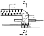
В примере 2 описано порционирующее устройство, соответствующее условиям высокого давления, и с возможностью обслуживания двух шлюзовых устройств. На Фиг.2a и 2b показан пример 2.Example 2 describes a portioning device corresponding to high pressure conditions and with the possibility of servicing two gateway devices. 2a and 2b show example 2.
Фиг.2aFiga
Продукт переносится из зоны высокого давления с помощью шнекового конвейера 2.1 в корпусе 2.2. Поперечный шнековый конвейер в корпусе 2.4 может вращаться в обоих направлениях и переносить продукт переменно через пневматические затворы 2.5.1 и 2.5.2, и в шлюзовые камеры 2.6.1 и 2.6.2. Когда поперечный шнековый конвейер загружает, например, шлюзовую камеру 2.6.1, область пространства, не содержащая частиц продукта, образуется вокруг пневматического затвора 2.5.2. Когда шлюзовая камера 2.6.2 загружается, область пространства, не содержащая частиц продукта, образуется вокруг пневматического затвора 2.5.1.The product is transported from the high pressure zone using a screw conveyor 2.1 in the housing 2.2. The transverse screw conveyor in housing 2.4 can rotate in both directions and carry the product alternately through pneumatic valves 2.5.1 and 2.5.2, and into the lock chambers 2.6.1 and 2.6.2. When the cross auger conveyor loads, for example, a lock chamber 2.6.1, a region of space not containing product particles is formed around the pneumatic shutter 2.5.2. When the lock chamber 2.6.2 is loaded, a region of space free of product particles forms around the pneumatic shutter 2.5.1.
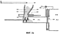
В примере 3 описано шлюзовое устройство, пригодное для использования, когда является приемлемым контролируемый выброс во время транспортировки продукта из зоны низкого давления в зону высокого давления. На Фиг.3a-3f показан пример 3.Example 3 describes a lock device suitable for use when a controlled release during transport of a product from a low pressure zone to a high pressure zone is acceptable. 3a-3f show example 3.
Фиг.3aFiga
Конвейер 3.1 перемещает порцию продукта в приемный лоток 3.3, снабженный 2 ленточными конвейерами 3.2, обеспечивающими сочетание сжатия и транспортировки. Порция продукта под давлением P1 принудительно вводится в шлюзовую камеру 3.6. через открытый пневматический затвор 3.4. Шнековый поршень 3.5., в своем положении под приемным лотком 3.3, переносит порцию продукта по направлению к закрытому выходному пневматическому затвору 3.8 под действием одного лишь его вращательного движения до тех пор, пока вся порция продукта не пройдет через входной пневматический затвор 3.4.Conveyor 3.1 transfers a portion of the product to the receiving tray 3.3, equipped with 2 belt conveyors 3.2, providing a combination of compression and transportation. A portion of the product under pressure P1 is forced into the airlock 3.6. through the open pneumatic shutter 3.4. The screw piston 3.5., In its position under the receiving tray 3.3, transfers a portion of the product towards the closed outlet pneumatic shutter 3.8 under the action of only its rotational movement until the entire portion of the product passes through the inlet pneumatic shutter 3.4.
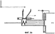
Фиг.3bFig.3b
Входной пневматический затвор закрыт.Air inlet shutter closed.
Фиг.3cFig. 3c
Давление в шлюзовой камере изменяется до нового давления P2 посредством выравнивающего клапана 3.9.The pressure in the lock chamber is changed to a new pressure P2 by means of an equalizing valve 3.9.
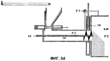
Фиг.3dFig.3d
Выходной пневматический затвор открыт, и поступательное аксиальное перемещение прессующего шнека 3.5 добавляется к вращению с аксиальным перемещением, которое принудительно выгружает порции продукта из шлюзовой камеры 3.6, через выходной пневматический затвор, и в новую зону с заданным давлением 3.10.The output pneumatic shutter is open, and the translational axial movement of the pressing screw 3.5 is added to the rotation with axial movement, which forcibly unloads portions of the product from the lock chamber 3.6, through the output pneumatic shutter, and into a new zone with a given pressure of 3.10.
Фиг.3eFig. 3e
Выходной пневматический затвор 3.8 закрыт, когда прессующий шнек 3.5 втягивается назад в шлюзовую камеру 3.6, под действием его поступательного аксиального перемещения.The output pneumatic shutter 3.8 is closed when the pressing screw 3.5 is retracted back into the lock chamber 3.6, under the action of its translational axial movement.
Фиг.3fFig.3f
Давление изменяется до давления P1 первой зоны под давлением посредством выравнивающего клапана 3.9, после чего входной пневматический затвор 3.4 открывается, и следующая порция продукта может загружаться в шлюзовую камеру.The pressure is changed to the pressure P1 of the first pressure zone by means of an equalizing valve 3.9, after which the pneumatic inlet valve 3.4 opens, and the next portion of the product can be loaded into the lock chamber.
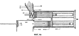
В примере 4 описан вариант шлюзового устройства, пригодный для использования, когда выброс во время транспортировки продукта из зоны низкого давления в зону высокого давления является неприемлемым. Поток продукта поворачивается на 180°, проходя через шлюзовое устройство. На Фиг.4a-4e показан пример 4.Example 4 describes a variant of a lock device suitable for use when the release during transport of a product from a low pressure zone to a high pressure zone is unacceptable. Product flow is rotated 180 ° through a gateway device. 4a-4e show example 4.
Фиг.4aFiga
Порция продукта переносится в приемный лоток 4.1, снабженный двумя ленточными конвейерами 4.2. В это время пневматический затвор 4.8 открыт. Прессующий шнек 4.5, расположенный на входе 4.3, принудительно загружает порцию продукта в шлюзовую камеру 4.6.1 под действием только его вращательного движения. Шлюзовая камера 4.6.1 загружается и разгружается через одно и то же отверстие и может вращаться вокруг оси 4.12, параллельной оси прессующего шнека, и снабжена поршнем 4.11.1. В этом варианте вторая шлюзовая камера 4.6.2 расположена симметрично по отношению к оси 4.12 и снабжена поршнем 4.11.2. Две шлюзовые камеры, вместе с их поршнями и средствами для перемещения поршней, составляют ротор 4.13, который может вращаться вокруг оси 4.12 и перемещаться поступательно посредством аксиального смещения.A portion of the product is transferred to the receiving tray 4.1, equipped with two belt conveyors 4.2. At this time, the pneumatic shutter 4.8 is open. Pressing auger 4.5, located at the inlet 4.3, forcibly loads a portion of the product into the lock chamber 4.6.1 under the action of only its rotational movement. The lock chamber 4.6.1 is loaded and unloaded through the same hole and can rotate around an axis 4.12 parallel to the axis of the pressing screw and is equipped with a piston 4.11.1. In this embodiment, the second lock chamber 4.6.2 is located symmetrically with respect to the axis 4.12 and is equipped with a piston 4.11.2. Two lock chambers, together with their pistons and means for moving the pistons, make up the rotor 4.13, which can rotate around the axis 4.12 and move translationally by axial displacement.
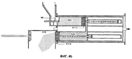
Фиг.4bFig.4b
Поршень 4.11.1 шлюзовой камеры во время принудительной загрузки перемещается от исходной позиции в отверстии шлюзовой камеры по направлению к задней части шлюзовой камеры 4.6.1. Другой поршень 4.11.2 шлюзовой камеры в это время перемещается из исходного положения в задней части шлюзовой камеры по направлению к отверстию и через него, принудительно выгружая порцию продукта из шлюзовой камеры во вторую зону 4.10 под давлением. Прессующий шнек 4.5 принудительно выгружает порцию продукта через отверстие шлюзовой камеры 4.6.1 путем поступательного аксиального перемещения в дополнение к вращательному движению.The lock chamber piston 4.11.1 during forced loading moves from its original position in the lock chamber opening towards the rear of the lock chamber 4.6.1. Another piston 4.11.2 of the lock chamber at this time moves from the initial position in the rear of the lock chamber towards the hole and through it, forcibly unloading a portion of the product from the lock chamber into the second zone 4.10 under pressure. The compression screw 4.5 forcibly unloads a portion of the product through the opening of the lock chamber 4.6.1 by axial translational movement in addition to the rotational movement.
Фиг.4cFig.4c
Поршень 4.11.2 втягивается назад настолько далеко, что он совмещается с отверстием шлюзовой камеры 4.6.2, и пневматический затвор 4.8 закрывается путем его перемещения к входу 4.7 зоны высокого давления, и прессующий шнек 4.5 втягивается назад до его положения на входе 4.3 шлюзовой камеры.The piston 4.11.2 is pulled back so far that it aligns with the opening of the lock chamber 4.6.2, and the pneumatic shutter 4.8 is closed by moving it to the inlet of the high pressure zone 4.7, and the compression screw 4.5 is pulled back to its position at the inlet 4.3 of the lock chamber.
Фиг.4dFig.4d
Пневматические затворы 4.4.1 и 4.4.2 открыты под действием поступательного осевого перемещения ротора от входного лотка 4.1 и входа 4.7 в зону высокого давления. После этого, ротор поворачивается на 180°, при этом шлюзовая камера 4.6.1 должна поменяться местами со шлюзовой камерой 4.6.2.The pneumatic valves 4.4.1 and 4.4.2 are open under the action of translational axial movement of the rotor from the input tray 4.1 and the entrance 4.7 to the high-pressure zone. After that, the rotor rotates 180 °, while the lock chamber 4.6.1 should change places with the lock chamber 4.6.2.
Фиг.4eFig.4e
Пневматические затворы 4.4.1 и 4.4.2 закрыты путем втягивания ротора 4.13, и шлюзовая камера 4.6.2 становится готовой для принудительной загрузки следующей порции продукта, и давление в шлюзовой камере 4.6.1 изменяется до высокого давления P2 с помощью выравнивающего клапана 4.9. После этого пневматический затвор 4.8 открывается, и шлюзовая камера 4.6.1 готова к разгрузке.The pneumatic valves 4.4.1 and 4.4.2 are closed by retracting the rotor 4.13, and the lock chamber 4.6.2 is ready to force the next batch of product to be forced, and the pressure in the lock chamber 4.6.1 is changed to high pressure P2 using the equalizing valve 4.9. After that, the pneumatic shutter 4.8 opens and the lock chamber 4.6.1 is ready for unloading.
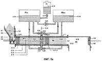
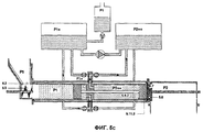
В примере 5 описан, подобно примеру 4, вариант шлюзового устройства, пригодный для использования тогда, когда выброс является неприемлемым, во время транспортировки продукта из зоны низкого давления в зону высокого давления. В противоположность примеру 4, ось ротора со шлюзовыми камерами в примере 5 является перпендикулярной оси шлюзовых камер и прессующего шнека. Это означает, что поток продукта должен поддерживать направление, придаваемое поршневым шнеком, при прохождении через шлюзовое устройство. В дополнение к этому, поршни, разгружающие шлюзовые камеры в примере 5, приводятся в действие жидкостью под давлением, которая в то же время служит в качестве очень эффективного герметизирующего устройства против утечки из зоны высокого давления в шлюзовую камеру во время принудительной разгрузки. Данный способ герметизации является особенно важным, когда температура зоны высокого давления является более высокой, чем та, которую могут выдержать традиционные герметизирующие материалы, например 700-1100°C, в газификаторе.Example 5 describes, like Example 4, a variant of a sluice device suitable for use when the discharge is unacceptable during the transportation of the product from the low pressure zone to the high pressure zone. In contrast to example 4, the axis of the rotor with lock chambers in example 5 is perpendicular to the axis of the lock chambers and the press screw. This means that the product flow must support the direction given by the piston screw as it passes through the lock device. In addition, the pistons discharging the lock chambers in Example 5 are driven by a pressurized fluid, which at the same time serves as a very effective sealing device against leakage from the high pressure zone into the lock chamber during forced unloading. This sealing method is especially important when the temperature of the high pressure zone is higher than that which traditional sealing materials, for example 700-1100 ° C, can withstand in a gasifier.
Фиг.5aFiga
Порция продукта переносится в приемный лоток 5.1, снабженный двумя ленточными конвейерами 5.2. В это же время пневматический затвор 5.8 открыт. Прессующий шнек 5.5, расположенный на входе 5.3, принудительно загружает порцию продукта в шлюзовую камеру 5.6.1 под действием только вращательного движения. Шлюзовая камера 5.6.1 загружается и разгружается через одно и то же отверстие, и может вращаться вокруг оси 5.12, перпендикулярной оси прессующего шнека, и снабжена поршнем 5.11.1. В этом варианте вторая шлюзовая камера 5.6.2 расположена симметрично по отношению к оси 5.12 и снабжена поршнем 5.11.2. Обе шлюзовые камеры и их поршни составляют ротор 5.13, который может вращаться вокруг оси 5.12 в корпусе ротора 5.15. Оба поршня 5.11.1 и 5.11.2 соединены поршневым штоком 5.14. Корпус ротора герметично соединен с приемным лотком 5.1 и зоной высокого давления 5.10.A portion of the product is transferred to the receiving tray 5.1, equipped with two belt conveyors 5.2. At the same time, the 5.8 air lock is open. Pressing screw 5.5, located at the inlet 5.3, forcibly loads a portion of the product into the lock chamber 5.6.1 under the action of only rotational movement. The lock chamber 5.6.1 is loaded and unloaded through the same hole, and can rotate around the axis 5.12, perpendicular to the axis of the pressing screw, and is equipped with a piston 5.11.1. In this embodiment, the second lock chamber 5.6.2 is located symmetrically with respect to the axis 5.12 and is equipped with a piston 5.11.2. Both lock chambers and their pistons make up the 5.13 rotor, which can rotate around the 5.12 axis in the 5.15 rotor housing. Both pistons 5.11.1 and 5.11.2 are connected by a piston rod 5.14. The rotor housing is hermetically connected to the receiving tray 5.1 and the high pressure zone 5.10.
Объединенное приводное и герметизирующее устройство для двойного поршня 5.11.1/5.11.2 состоит из контейнера 5.16 с резервуаром жидкости, которая может быть закачана с помощью насоса 5.17 в контейнер 5.18, частично заполненный жидкостью, тем самым поддерживая давление P1+ несколько более высоким, чем P1. Жидкость может перекачиваться с помощью насоса 5.20 из контейнера 5.18 в подобный ему контейнер 5.19, тем самым поддерживая давление P2++ несколько более высоким, чем P2. В дополнение к этому, объединенное приводное и герметизирующее устройство состоит из труб и проходов по оси 5.12 и 4 клапанов 5.21-5.24, с помощью которых две шлюзовые камеры 5.6.1 и 5.6.2 могут соединяться с двумя контейнерами 5.18 и 5.19. Когда шлюзовая камера 5.6.1 загружается, жидкость за поршнем 5.11.1 может проходить через 5.21 в 5.18, и, одновременно, эквивалентное количество жидкости должно проходить из 5.19 через 5.23 в часть шлюзовой камеры 5.6.2 за поршнем 5.11.2. Для поддержания заданных давлений эквивалентное количество жидкости должно одновременно перекачиваться из 5.18 в 5.19.The combined drive and sealing device for the double piston 5.11.1 / 5.11.2 consists of a container 5.16 with a reservoir of liquid, which can be pumped with a pump 5.17 into a container 5.18, partially filled with liquid, thereby maintaining the pressure P1 + slightly higher than P1 . The fluid can be pumped with a pump 5.20 from a container 5.18 into a container similar to it 5.19, thereby maintaining the pressure P2 ++ somewhat higher than P2. In addition, the combined drive and sealing device consists of pipes and passages along the axis 5.12 and 4 valves 5.21-5.24, with which two lock chambers 5.6.1 and 5.6.2 can be connected to two containers 5.18 and 5.19. When the lock chamber 5.6.1 is loaded, the fluid behind the piston 5.11.1 can pass through 5.21 to 5.18, and at the same time, an equivalent amount of fluid must pass from 5.19 through 5.23 to the part of the lock chamber 5.6.2 behind the piston 5.11.2. To maintain the given pressures, an equivalent amount of liquid must be simultaneously pumped from 5.18 to 5.19.
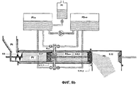
Фиг.5bFig.5b
Поршень шлюзовой камеры 5.11.1 во время принудительной загрузки перемещается от отверстия по направлению к задней части шлюзовой камеры 5.6.1. При этом поршень 5.11.2 в то же самое время должен перемещаться от задней части шлюзовой камеры 5.6.2 по направлению к отверстию и через него, принудительно выгружая порцию продукта из шлюзовой камеры во вторую зону 5.10 под давлением. Прессующий шнек 5.5 принудительно выгружает порцию продукта через отверстие шлюзовой камеры 5.6.1 под действием поступательного аксиального перемещения в дополнение к вращению.The lock chamber piston 5.11.1 during forced loading moves from the hole toward the rear of the lock chamber 5.6.1. In this case, the piston 5.11.2 at the same time should move from the back of the lock chamber 5.6.2 towards the hole and through it, forcibly unloading a portion of the product from the lock chamber into the second zone 5.10 under pressure. The pressing screw 5.5 forcibly unloads a portion of the product through the opening of the lock chamber 5.6.1 under the action of translational axial movement in addition to rotation.
Фиг.5cFig.5c
Пневматический затвор 5.8 закрыт путем его перемещения к входу 5.7 и, тем самым, он принудительно перемещает поршень 5.11.2 настолько далеко назад, что он совмещается с отверстием шлюзовой камеры 5.6.2. Прессующий шнек 5.5 втягивается назад, до его положения на входе 5.3.The pneumatic shutter 5.8 is closed by moving it to the input 5.7 and, thereby, it forces the piston 5.11.2 so far back that it aligns with the opening of the lock chamber 5.6.2. Pressing auger 5.5 is retracted back to its position at inlet 5.3.
Фиг.5dFig.5d
Пневматические затворы 5.4.1 и 5.4.2 открыты путем сокращения герметизирующих колец, и шаровые клапаны 5.21 и 5.23 закрыты. После этого ротор 5.13 поворачивается на 180°, при этом шлюзовая камера 5.6.1 должна поменяться местами со шлюзовой камерой 5.6.2.The pneumatic valves 5.4.1 and 5.4.2 are open by shortening the sealing rings, and the ball valves 5.21 and 5.23 are closed. After that, the rotor 5.13 rotates 180 °, while the lock chamber 5.6.1 should change places with the lock chamber 5.6.2.
Фиг.5e5e
Пневматические затворы 5.4.1 и 5.4.2 закрыты под действием расширения герметизирующих колец, и давление в шлюзовой камере 5.6.1 изменяется до высокого давления P2 с помощью выравнивающего клапана 5.9. После этого пневматический затвор 5.8 и шаровые клапаны 5.22 и 5.24 открываются, и шлюзовая камера 5.6.2 готова для принудительной загрузки следующей порции продукта, а шлюзовая камера 5.6.1 готова к принудительной разгрузке.The pneumatic valves 5.4.1 and 5.4.2 are closed by the expansion of the sealing rings, and the pressure in the lock chamber 5.6.1 is changed to high pressure P2 using the equalizing valve 5.9. After that, the pneumatic shutter 5.8 and the ball valves 5.22 and 5.24 open, and the lock chamber 5.6.2 is ready for forced loading of the next portion of the product, and the lock chamber 5.6.1 is ready for forced unloading.
Claims (17)
Applications Claiming Priority (2)
| Application Number | Priority Date | Filing Date | Title |
|---|---|---|---|
| DKPA200101208 | 2001-08-11 | ||
| DKPA20011208 | 2001-08-11 |
Publications (2)
| Publication Number | Publication Date |
|---|---|
| RU2004107132A RU2004107132A (en) | 2005-05-10 |
| RU2291742C2 true RU2291742C2 (en) | 2007-01-20 |
Family
ID=8160663
Family Applications (1)
| Application Number | Title | Priority Date | Filing Date |
|---|---|---|---|
| RU2004107132/15A RU2291742C2 (en) | 2001-08-11 | 2002-07-22 | Method and the device for transportation of the solid products in the form of particles between the areas with the different pressure |
Country Status (20)
| Country | Link |
|---|---|
| US (1) | US7600960B2 (en) |
| EP (1) | EP1425089B1 (en) |
| JP (1) | JP4282478B2 (en) |
| CN (1) | CN1553825B (en) |
| AT (1) | ATE356659T1 (en) |
| AU (1) | AU2002328275B2 (en) |
| BR (1) | BR0211834B1 (en) |
| CA (1) | CA2456782C (en) |
| DE (1) | DE60218870T2 (en) |
| DK (1) | DK1425089T3 (en) |
| ES (1) | ES2283588T3 (en) |
| HU (1) | HU228653B1 (en) |
| MX (1) | MXPA04001284A (en) |
| NO (1) | NO327681B1 (en) |
| NZ (1) | NZ531604A (en) |
| PL (1) | PL205563B1 (en) |
| PT (1) | PT1425089E (en) |
| RU (1) | RU2291742C2 (en) |
| WO (1) | WO2003013714A1 (en) |
| ZA (1) | ZA200401415B (en) |
Cited By (1)
| Publication number | Priority date | Publication date | Assignee | Title |
|---|---|---|---|---|
| RU2510878C1 (en) * | 2011-05-04 | 2014-04-10 | Ренмэтикс, Инк. | Self-purifying device and method for control of dense suspension pressure |
Families Citing this family (44)
| Publication number | Priority date | Publication date | Assignee | Title |
|---|---|---|---|---|
| CA2959268A1 (en) | 2005-07-19 | 2007-01-25 | Inbicon A/S | Method and apparatus for conversion of cellulosic material to ethanol |
| DE102006039622A1 (en) * | 2006-08-24 | 2008-02-28 | Spot Spirit Of Technology Ag | entry system |
| CN100434153C (en) * | 2007-02-12 | 2008-11-19 | 西安交通大学 | Spherical high temperature and high pressure continuous feeding airlock system |
| US20090022570A1 (en) * | 2007-07-16 | 2009-01-22 | Joe David Craig | System, method and apparatus for feeding biomass into a pressurized vessel |
| US7976259B2 (en) * | 2007-07-16 | 2011-07-12 | Joe David Craig | System for feeding biomass into a pressurized vessel |
| ATE503027T1 (en) | 2007-07-25 | 2011-04-15 | Haarslev As | METHOD AND SYSTEM FOR THE PRETREATMENT OF LIGNOCELLULOSIC MATERIAL |
| US20090110517A1 (en) * | 2007-10-29 | 2009-04-30 | Leon Yuan | Catalyst Flow Control Device for Transfer of Solids Between Two Vessels |
| US20100014946A1 (en) * | 2007-10-29 | 2010-01-21 | Uop Llc | Catalyst flow control device for transfer of solids between two vessels |
| US8057639B2 (en) † | 2008-02-28 | 2011-11-15 | Andritz Inc. | System and method for preextraction of hemicellulose through using a continuous prehydrolysis and steam explosion pretreatment process |
| CA2749184C (en) * | 2009-01-13 | 2017-07-04 | Biogasol Ipr Aps | Method and apparatus for in-feeding of matter to a process reactor |
| US9211515B2 (en) * | 2009-08-27 | 2015-12-15 | Inbicon A/S | Particle pump methods and devices |
| KR20120091213A (en) | 2009-10-14 | 2012-08-17 | 티케이 에너지 에이/에스 | A piston member, an apparatus comprising the piston member, and methods and use of the piston member and the apparatus |
| US20110173885A1 (en) * | 2010-01-19 | 2011-07-21 | Hatch Ltd. | Atmospheric pressure gasification process and system |
| CA2795503C (en) | 2010-03-19 | 2020-02-18 | Poet Research, Inc. | System for treatment of biomass to facilitate the production of ethanol |
| US10533203B2 (en) | 2010-03-19 | 2020-01-14 | Poet Research, Inc. | System for the treatment of biomass |
| US8647012B2 (en) * | 2010-05-05 | 2014-02-11 | Energy Absorption Systems, Inc. | Gate for barrier system and methods for the assembly and use thereof |
| IT1402202B1 (en) * | 2010-09-29 | 2013-08-28 | Chemtex Italia S R L Ora Chemtex Italia S P A | IMPROVED PROCEDURE TO RECOVER SUGAR FROM A LIGNOCELLULOSIC BIOMASS PRETREATMENT FLOW |
| WO2012061742A1 (en) | 2010-11-05 | 2012-05-10 | ThermoChem Recovery International | Solids circulation system and method for capture and conversion of reactive solids |
| WO2012099967A1 (en) | 2011-01-18 | 2012-07-26 | Poet, Llc | Systems and methods for hydrolysis of biomass |
| WO2013006856A1 (en) | 2011-07-07 | 2013-01-10 | Poet Research Incorporated | Systems and methods for acid recycle |
| CN103958398B (en) | 2011-09-27 | 2016-01-06 | 国际热化学恢复股份有限公司 | Synthetic gas cleaning system and method |
| SE537195C2 (en) * | 2012-02-22 | 2015-03-03 | Valmet Oy | Feeding device, system and method for handling non-wood based plant material |
| WO2014143168A1 (en) * | 2013-03-15 | 2014-09-18 | Koenig Mark E | Outlet tube for a material transfer system |
| WO2014168604A1 (en) | 2013-04-08 | 2014-10-16 | Thermochem Recovery International, Inc. | Hydraulic feeder system having compression stage with multi-cylinder hydraulic circuit |
| CN103387852B (en) * | 2013-07-25 | 2015-02-11 | 中科合成油内蒙古有限公司 | Method and device for conveying calcium-containing solid particles from normal-pressure environment to high-pressure environment |
| MY182510A (en) | 2014-10-29 | 2021-01-25 | Cambi Tech As | Method and device for treating biomass and organic waste |
| EP3054051A1 (en) | 2015-02-09 | 2016-08-10 | BETA RENEWABLES S.p.A. | Process to transfer a ligno-cellulosic feedstock |
| EP3054050B1 (en) | 2015-02-09 | 2018-01-24 | BETA RENEWABLES S.p.A. | Pretreatment process of a ligno-cellulosic feedstock |
| EP3054052A1 (en) | 2015-02-09 | 2016-08-10 | BETA RENEWABLES S.p.A. | Improved process to transfer a ligno-cellulosic feedstock |
| EP3300505B1 (en) * | 2015-03-05 | 2020-04-29 | Schenck Process Europe GmbH | Device and method for conveying bulk solid materials |
| CH711261A1 (en) * | 2015-06-30 | 2016-12-30 | Lehmann Markus | Plant for the implementation of a continuous, multi-stage industrial process. |
| US11242988B2 (en) | 2016-02-16 | 2022-02-08 | Thermochem Recovery International, Inc. | Two-stage energy-integrated product gas generation system and method |
| MX2018011589A (en) | 2016-03-25 | 2019-09-18 | Thermochem Recovery Int Inc | Three-stage energy-integrated product gas generation system and method. |
| US10197015B2 (en) * | 2016-08-30 | 2019-02-05 | Thermochem Recovery International, Inc. | Feedstock delivery system having carbonaceous feedstock splitter and gas mixing |
| US10197014B2 (en) | 2016-08-30 | 2019-02-05 | Thermochem Recovery International, Inc. | Feed zone delivery system having carbonaceous feedstock density reduction and gas mixing |
| US10364398B2 (en) | 2016-08-30 | 2019-07-30 | Thermochem Recovery International, Inc. | Method of producing product gas from multiple carbonaceous feedstock streams mixed with a reduced-pressure mixing gas |
| CA3040380A1 (en) | 2016-11-04 | 2018-05-11 | Inbicon A/S | Method for preparing fermentable sugars from lignocellulosic biomass |
| CN106516752A (en) * | 2016-11-11 | 2017-03-22 | 航天长征化学工程股份有限公司 | Plunger type pulverized coal pressurized conveying device |
| IT201700047403A1 (en) * | 2017-05-03 | 2018-11-03 | Ima Spa | Apparatus and Method for Coatings Bulk Material |
| US9920926B1 (en) | 2017-07-10 | 2018-03-20 | Thermochem Recovery International, Inc. | Pulse combustion heat exchanger system and method |
| US10099200B1 (en) | 2017-10-24 | 2018-10-16 | Thermochem Recovery International, Inc. | Liquid fuel production system having parallel product gas generation |
| CN110040447B (en) * | 2019-04-23 | 2020-12-08 | 山东友邦肥业科技有限公司 | Spiral recovery unit for feed cylinder |
| US11555157B2 (en) | 2020-03-10 | 2023-01-17 | Thermochem Recovery International, Inc. | System and method for liquid fuel production from carbonaceous materials using recycled conditioned syngas |
| US11466223B2 (en) | 2020-09-04 | 2022-10-11 | Thermochem Recovery International, Inc. | Two-stage syngas production with separate char and product gas inputs into the second stage |
Family Cites Families (23)
| Publication number | Priority date | Publication date | Assignee | Title |
|---|---|---|---|---|
| US2732086A (en) * | 1956-01-24 | Apparatus for feeding solids into | ||
| SE218793C1 (en) * | ||||
| US2765899A (en) * | 1952-04-29 | 1956-10-09 | Wallace & Tiernan Inc | Dry feeder |
| GB1011822A (en) * | 1962-07-16 | 1965-12-01 | Smidth & Co As F L | Improvements relating to methods of feeding materials and to screw conveyors |
| SE399734B (en) * | 1976-07-05 | 1978-02-27 | Stabilator Ab | KIT AND DEVICE FOR PIPE TRANSPORT OF MATERIAL |
| SE456645B (en) * | 1983-02-28 | 1988-10-24 | Christopher Sylwan | Y=shaped branch pipe for pressure reactor feed |
| FR2626783B1 (en) * | 1988-02-05 | 1990-07-20 | Renault | DEVICE FOR MICROWAVE REMOVAL OF CARBON PARTICLES CONTAINED IN EXHAUST GASES OF HEAT ENGINES |
| US5044837A (en) * | 1989-09-14 | 1991-09-03 | Phillips Petroleum Company | Method and apparatus for continuously feeding particulate solid material into a pressurized system without pressure loss |
| FI85186C (en) | 1989-12-07 | 1996-02-13 | Ahlstroem Oy | Method and apparatus for feeding fuel into a pressurized space |
| SE468764B (en) | 1990-10-04 | 1993-03-15 | Sydkraft Ab | SET FOR INPUT OF BULK MATERIAL IN A SPACE UNDER OVERPRESSED |
| US5087272A (en) * | 1990-10-17 | 1992-02-11 | Nixdorf Richard D | Filter and means for regeneration thereof |
| SE469070B (en) * | 1991-06-20 | 1993-05-10 | Sydkraft Ab | DEVICE FOR INPUT OF BULK MATERIAL IN A SPACE UNDER PRESSURE |
| SE469536B (en) * | 1991-12-05 | 1993-07-19 | Vattenfall Energisyst Ab | SEAT AND DEVICE FOR INPUT OF FRAGMENTED MATERIAL TO PRESSURE CONTAINERS |
| FI92250C (en) * | 1992-03-30 | 1994-10-10 | Kone Oy | Method and apparatus for feeding a substance to a pressurized space |
| DE4217204C2 (en) | 1992-05-23 | 1994-04-14 | Abel Gmbh & Co | Solid fuel pump |
| DE4236242A1 (en) * | 1992-10-27 | 1994-04-28 | Dornier Gmbh | Process for reducing soot particles in exhaust gas flows |
| SE500516C2 (en) * | 1992-11-13 | 1994-07-11 | Vattenfall Energisyst Ab | Device for feeding wood chips - involves material transported via feed-in chamber using reciprocating screw piston to collection container under pressure |
| FI95504C (en) * | 1994-08-26 | 1996-02-12 | Andritz Patentverwaltung | Method and apparatus for equalizing the pressure in a piston feeder |
| FI98407C (en) * | 1994-09-22 | 1997-06-10 | Imatran Voima Oy | A method and apparatus for feeding a solid to a pressurized space |
| US5658123A (en) * | 1995-09-15 | 1997-08-19 | Advanced Micro Devices, Inc. | Container-less transfer of semiconductor wafers through a barrier between fabrication areas |
| US6284202B1 (en) * | 1997-10-03 | 2001-09-04 | Cha Corporation | Device for microwave removal of NOx from exhaust gas |
| DE19818935A1 (en) * | 1998-04-28 | 1999-11-04 | Klaus Spies | Method and device for introducing solid, bulk-like to liquid-pasty substances in process sequences, especially conveyor systems with a higher pressure level |
| WO2003028773A1 (en) * | 2001-10-04 | 2003-04-10 | The Johns Hopkins University | Airborne pathogen neutralization |
-
2002
- 2002-07-22 ES ES02762271T patent/ES2283588T3/en not_active Expired - Lifetime
- 2002-07-22 WO PCT/DK2002/000507 patent/WO2003013714A1/en active IP Right Grant
- 2002-07-22 EP EP02762271A patent/EP1425089B1/en not_active Expired - Lifetime
- 2002-07-22 DE DE60218870T patent/DE60218870T2/en not_active Expired - Lifetime
- 2002-07-22 US US10/486,102 patent/US7600960B2/en not_active Expired - Fee Related
- 2002-07-22 NZ NZ531604A patent/NZ531604A/en not_active IP Right Cessation
- 2002-07-22 MX MXPA04001284A patent/MXPA04001284A/en active IP Right Grant
- 2002-07-22 PT PT02762271T patent/PT1425089E/en unknown
- 2002-07-22 JP JP2003518709A patent/JP4282478B2/en not_active Expired - Fee Related
- 2002-07-22 PL PL368194A patent/PL205563B1/en unknown
- 2002-07-22 RU RU2004107132/15A patent/RU2291742C2/en not_active IP Right Cessation
- 2002-07-22 CN CN028175999A patent/CN1553825B/en not_active Expired - Fee Related
- 2002-07-22 AU AU2002328275A patent/AU2002328275B2/en not_active Ceased
- 2002-07-22 AT AT02762271T patent/ATE356659T1/en active
- 2002-07-22 HU HU0401027A patent/HU228653B1/en not_active IP Right Cessation
- 2002-07-22 BR BRPI0211834-3A patent/BR0211834B1/en not_active IP Right Cessation
- 2002-07-22 CA CA2456782A patent/CA2456782C/en not_active Expired - Fee Related
- 2002-07-22 DK DK02762271T patent/DK1425089T3/en active
-
2004
- 2004-02-02 NO NO20040470A patent/NO327681B1/en not_active IP Right Cessation
- 2004-02-20 ZA ZA2004/01415A patent/ZA200401415B/en unknown
Cited By (2)
| Publication number | Priority date | Publication date | Assignee | Title |
|---|---|---|---|---|
| RU2510878C1 (en) * | 2011-05-04 | 2014-04-10 | Ренмэтикс, Инк. | Self-purifying device and method for control of dense suspension pressure |
| US8801859B2 (en) | 2011-05-04 | 2014-08-12 | Renmatix, Inc. | Self-cleaning apparatus and method for thick slurry pressure control |
Also Published As
| Publication number | Publication date |
|---|---|
| DK1425089T3 (en) | 2007-11-26 |
| ES2283588T3 (en) | 2007-11-01 |
| US20040184900A1 (en) | 2004-09-23 |
| PL368194A1 (en) | 2005-03-21 |
| NZ531604A (en) | 2005-11-25 |
| CA2456782C (en) | 2011-10-25 |
| HUP0401027A2 (en) | 2004-09-28 |
| US7600960B2 (en) | 2009-10-13 |
| HUP0401027A3 (en) | 2009-05-28 |
| BR0211834B1 (en) | 2012-09-04 |
| EP1425089B1 (en) | 2007-03-14 |
| RU2004107132A (en) | 2005-05-10 |
| JP4282478B2 (en) | 2009-06-24 |
| NO327681B1 (en) | 2009-09-07 |
| JP2004536754A (en) | 2004-12-09 |
| PT1425089E (en) | 2007-06-05 |
| WO2003013714A1 (en) | 2003-02-20 |
| CN1553825B (en) | 2010-06-16 |
| ZA200401415B (en) | 2005-01-26 |
| EP1425089A1 (en) | 2004-06-09 |
| MXPA04001284A (en) | 2005-06-06 |
| AU2002328275B2 (en) | 2008-03-06 |
| NO20040470L (en) | 2004-03-31 |
| DE60218870D1 (en) | 2007-04-26 |
| DE60218870T2 (en) | 2007-11-29 |
| CN1553825A (en) | 2004-12-08 |
| BR0211834A (en) | 2004-09-08 |
| PL205563B1 (en) | 2010-05-31 |
| ATE356659T1 (en) | 2007-04-15 |
| HU228653B1 (en) | 2013-05-28 |
| CA2456782A1 (en) | 2003-02-20 |
Similar Documents
| Publication | Publication Date | Title |
|---|---|---|
| RU2291742C2 (en) | Method and the device for transportation of the solid products in the form of particles between the areas with the different pressure | |
| AU2002328275A1 (en) | Method for transfer of particulate solid products between zones of different pressure. | |
| KR20120069696A (en) | Particle pump methods and devices | |
| EP0431639B1 (en) | Method and apparatus for feeding fuel into a pressurized space | |
| US5044837A (en) | Method and apparatus for continuously feeding particulate solid material into a pressurized system without pressure loss | |
| US4148405A (en) | Solid feeder and method | |
| EP0782474B1 (en) | Method and apparatus for feeding solid material into a pressurized space | |
| CN107406779B (en) | Device and method for conveying bulk material | |
| CN111606053A (en) | Rotary powder pressurizing and conveying device | |
| NZ248895A (en) | Transfer device having intermittently rotated carousel having through passageways with assembly sealing pressure maximised during rotor dwell periods | |
| Schell | High pressure solids feeding using a lockhopper system: design and operating experience | |
| FI88539C (en) | Method and apparatus for transporting solids from one pressure to another | |
| FI20170097A1 (en) | Feeder for a pyrolysis apparatus | |
| JPS61124440A (en) | Powdery material feeding and discharging device | |
| GB2602882A (en) | Biomass steam explosion apparatus | |
| SU877295A1 (en) | Sintering machine | |
| SU1355677A1 (en) | Sluice-type feeder of hydraulic conveying system of suction dredger |
Legal Events
| Date | Code | Title | Description |
|---|---|---|---|
| PC4A | Invention patent assignment |
Effective date: 20081031 |
|
| MM4A | The patent is invalid due to non-payment of fees |
Effective date: 20160723 |